

Enhancing NOMA’s Spectrum Efficiency in a 5G Network through Cooperative Spectrum Sharing

 , ,
, ,  , and
, and
Abstract
:1. Introduction
2. Related Work
3. System Model
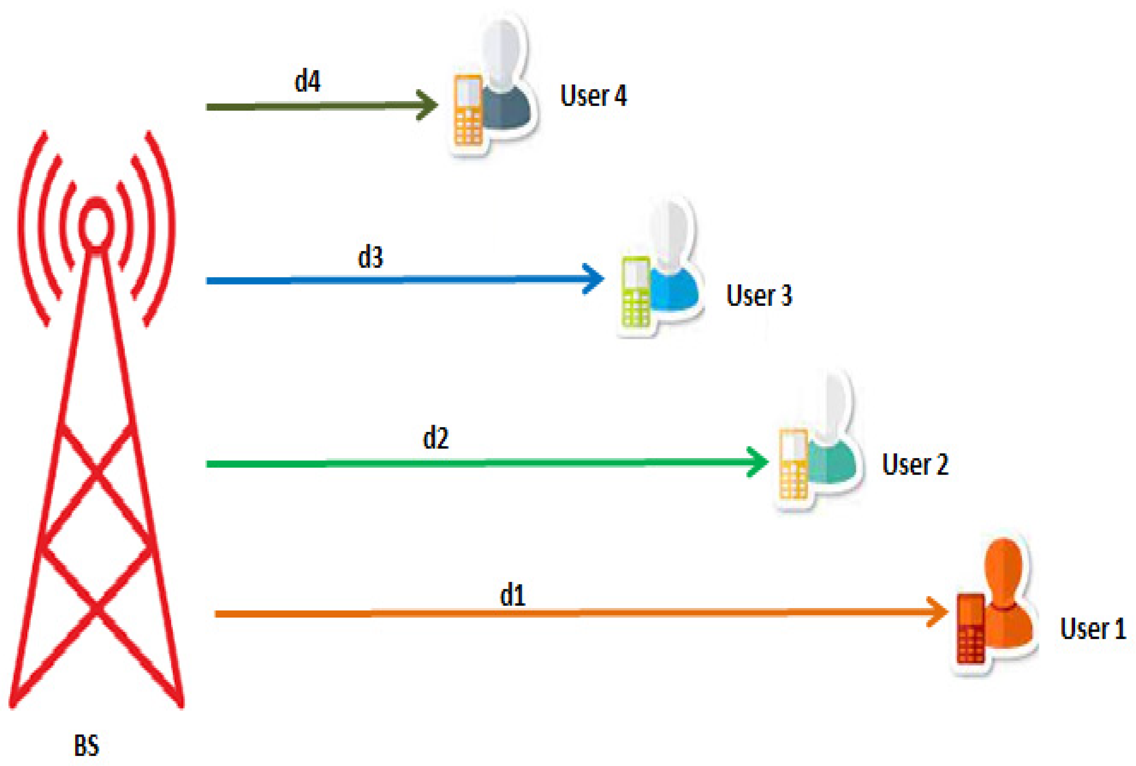
3.1. SIOS DL NOMA
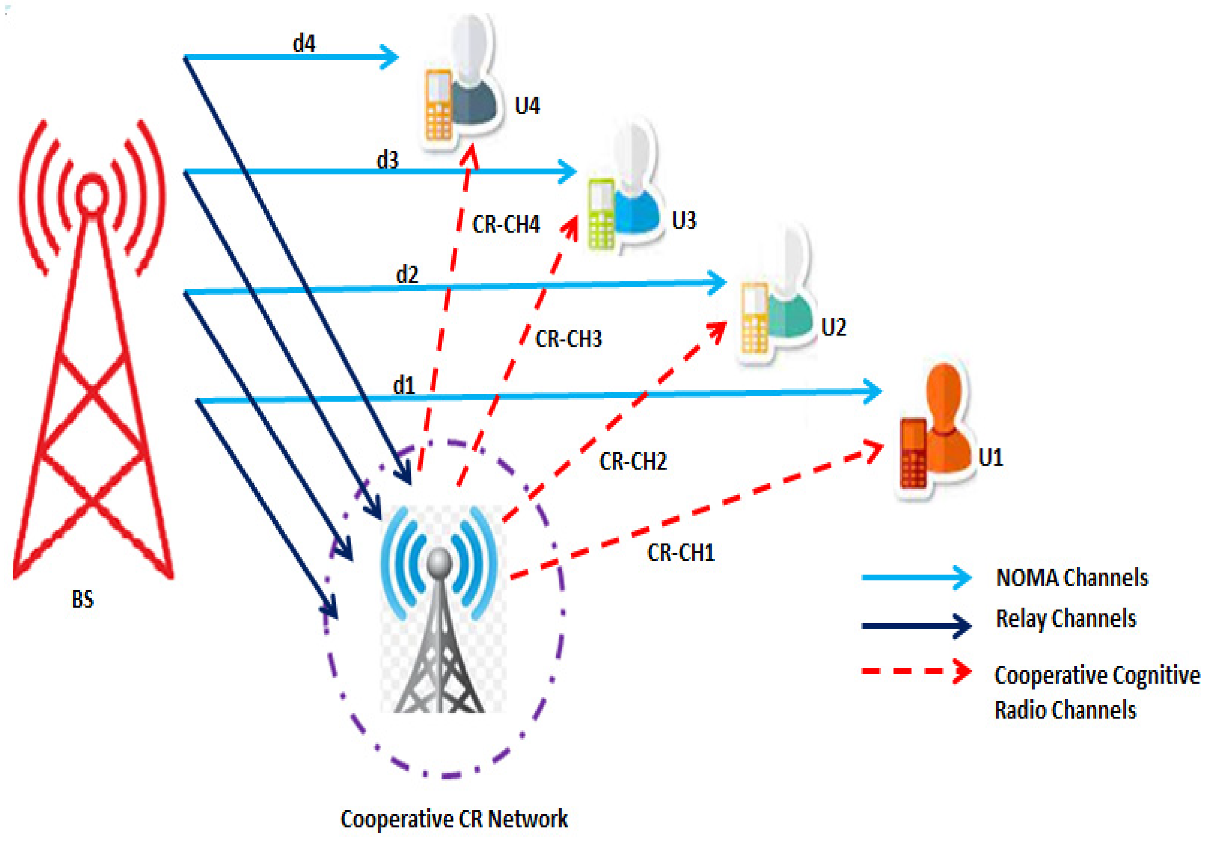
3.1.1. CCRN-Based Free Channels
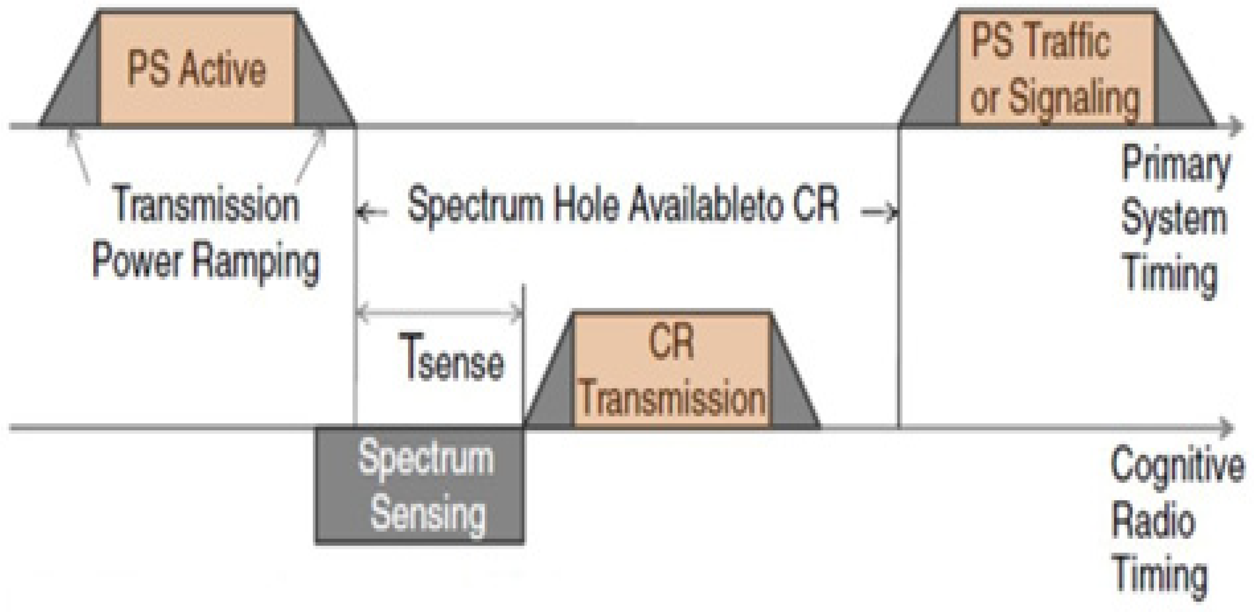
Spectrum Sensing
Energy Detection
3.1.2. CCR-Based Dedicated Channel
3.2. MIMO DL PD NOMA
3.3. Massive MIMO DL PD NOMA
4. Numerical Simulation and Results
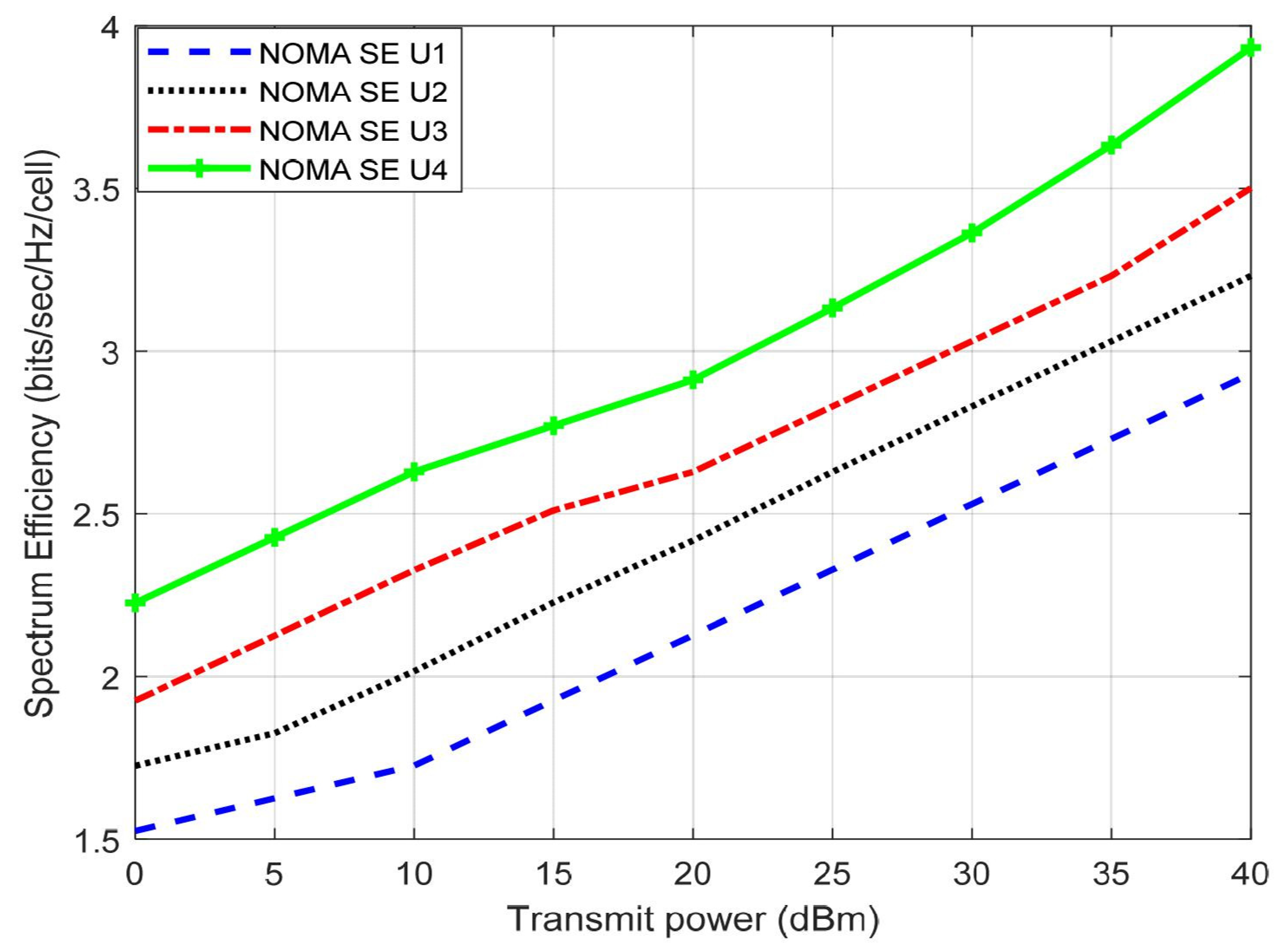
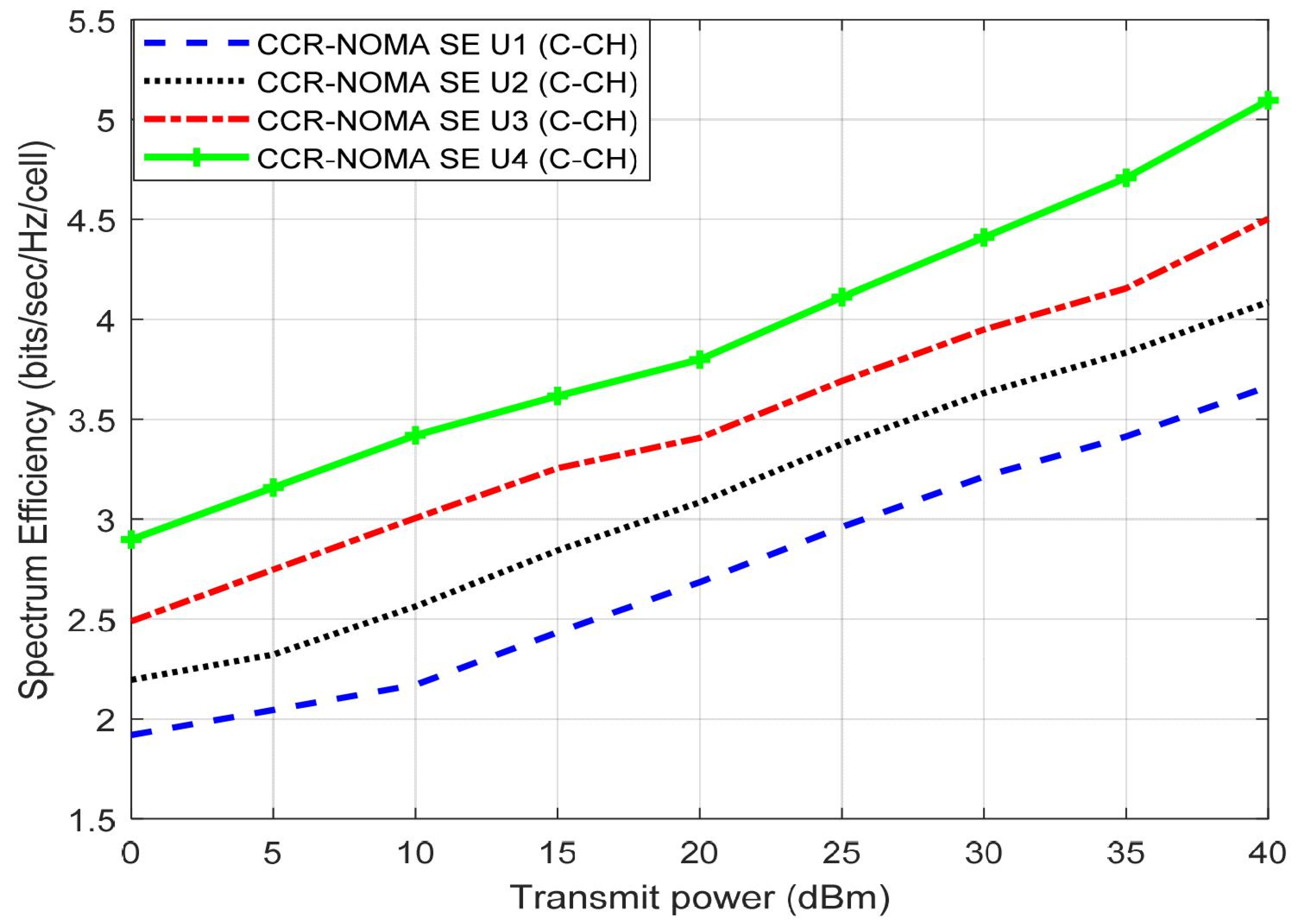
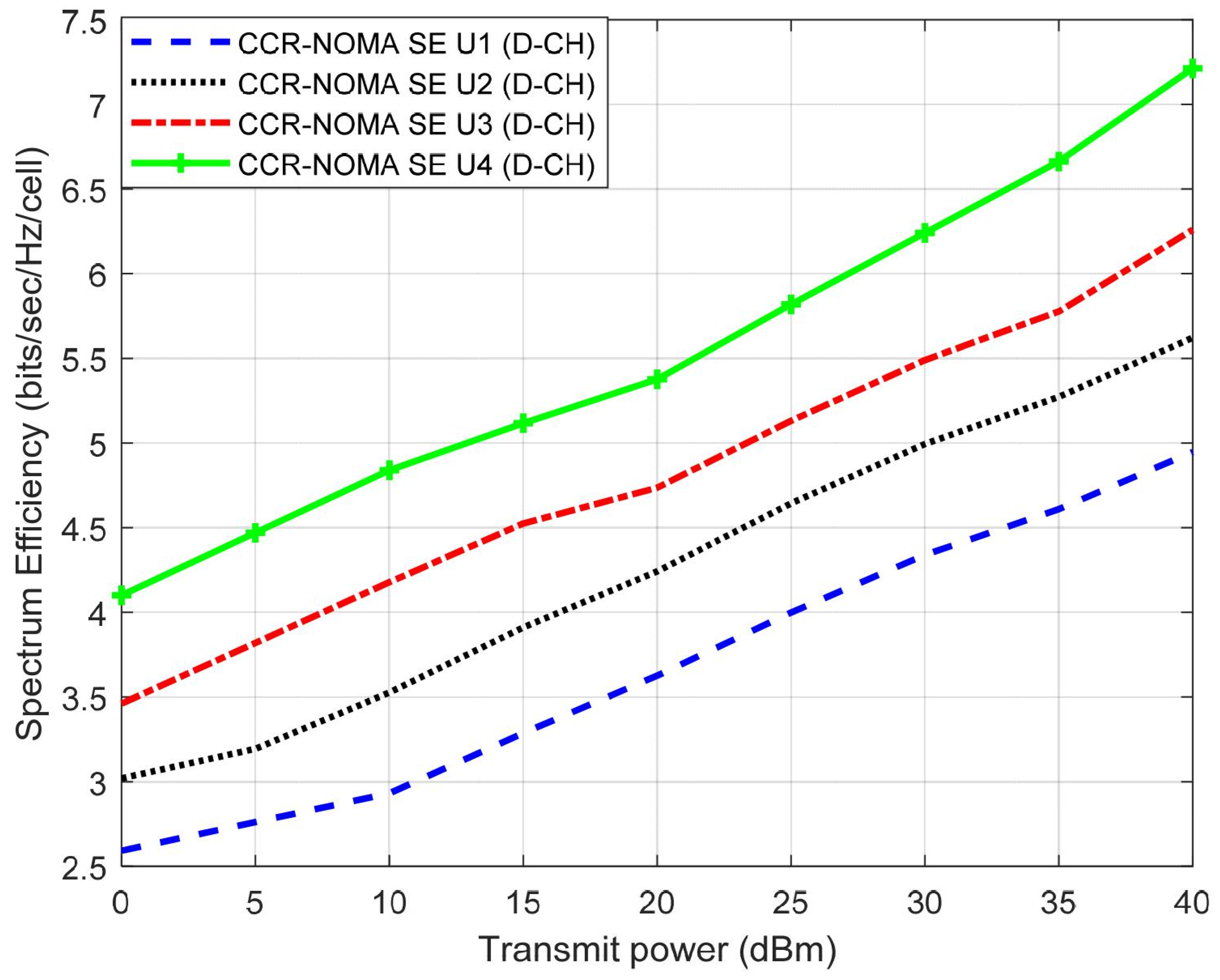
4.1. SISO DL NOMA PD
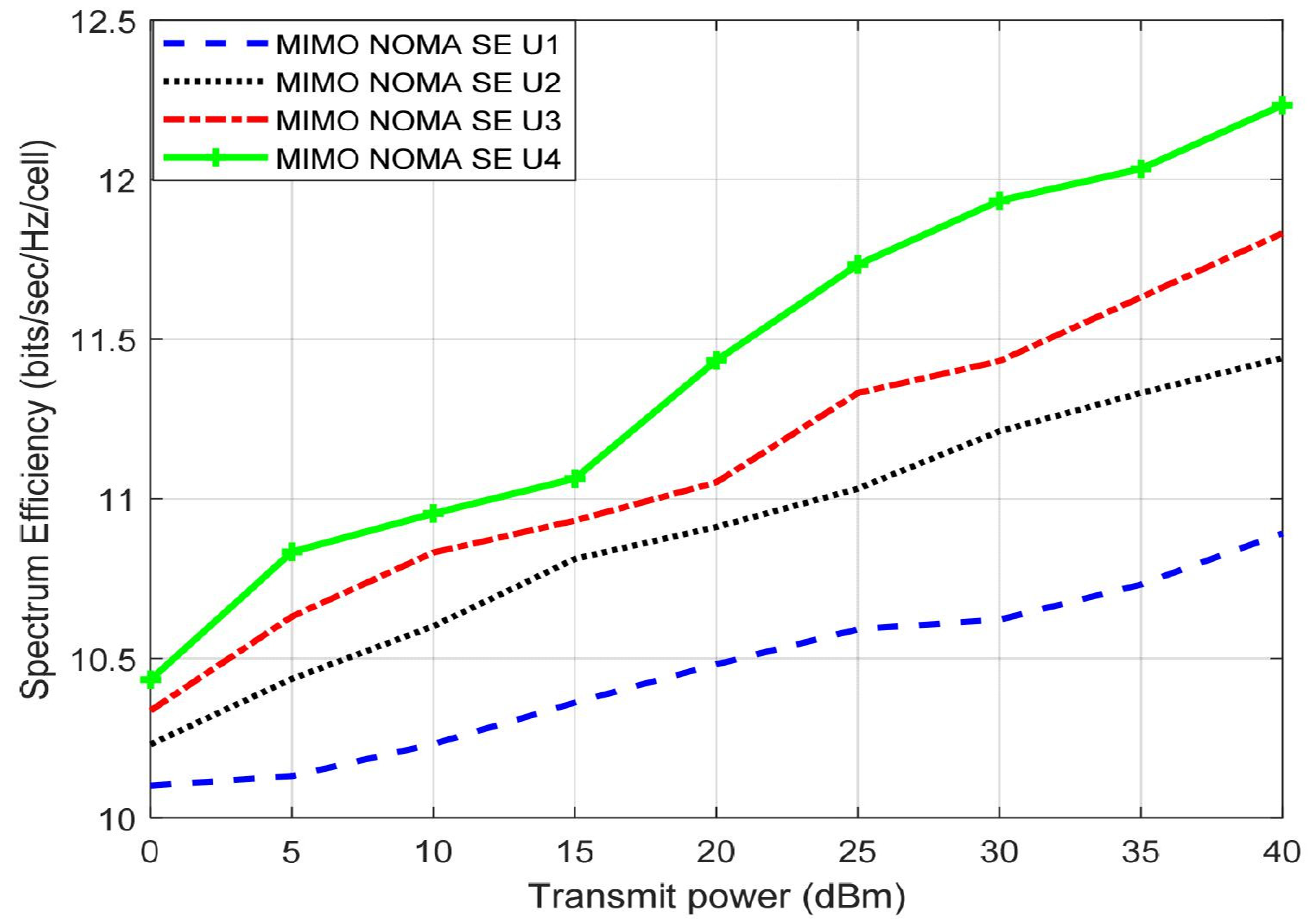
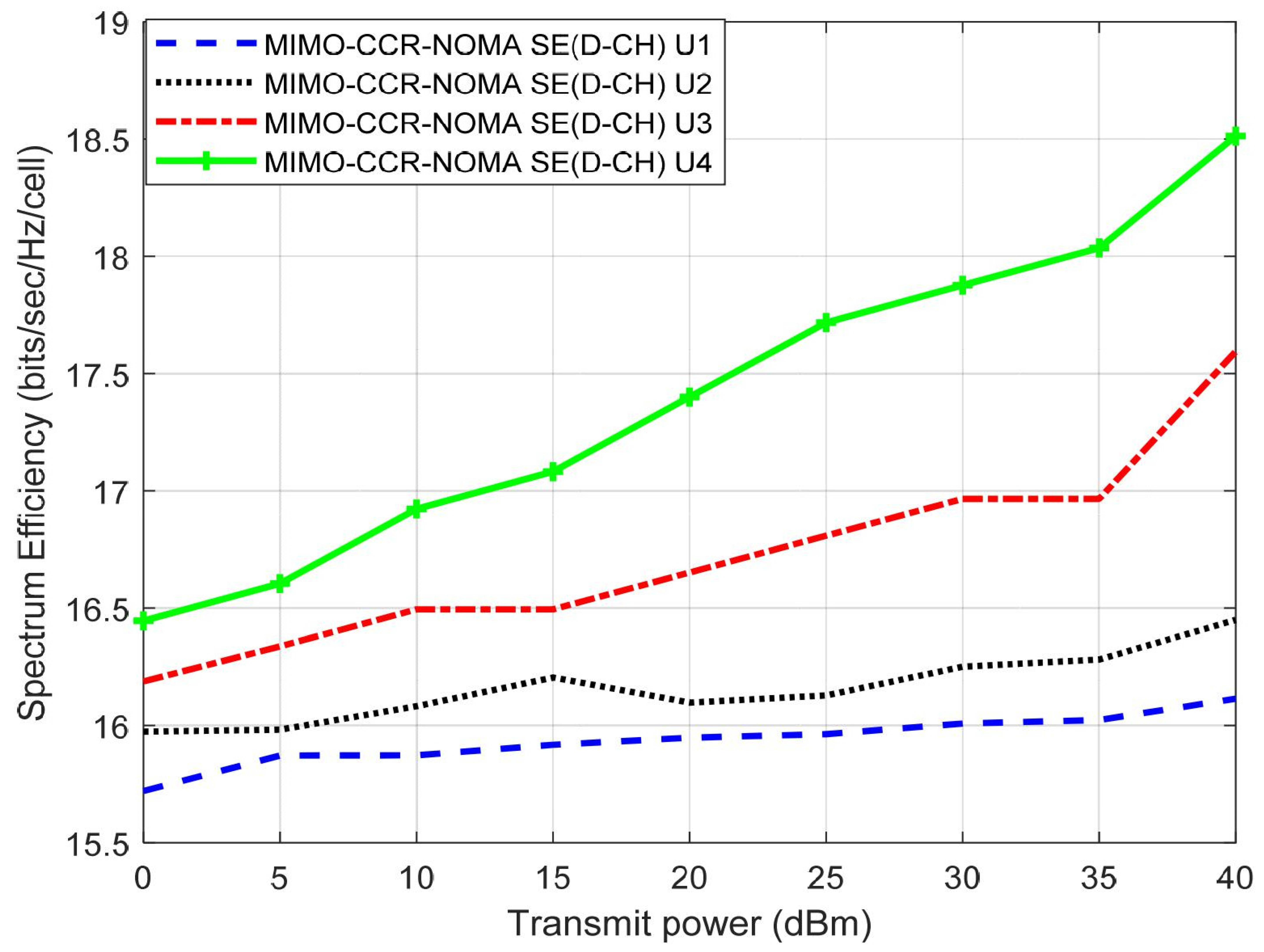
4.2. MIMO DL-NOMA PD
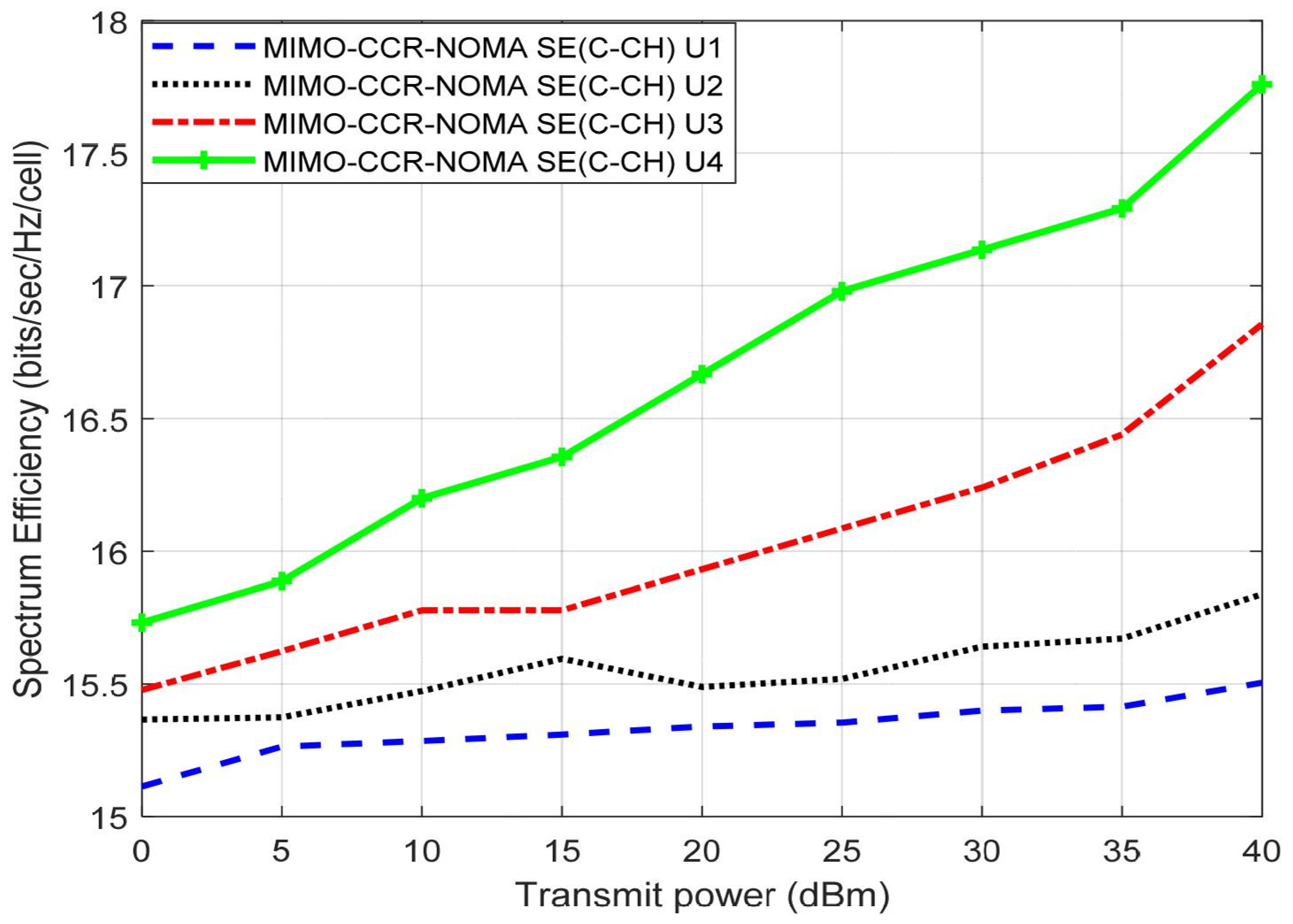
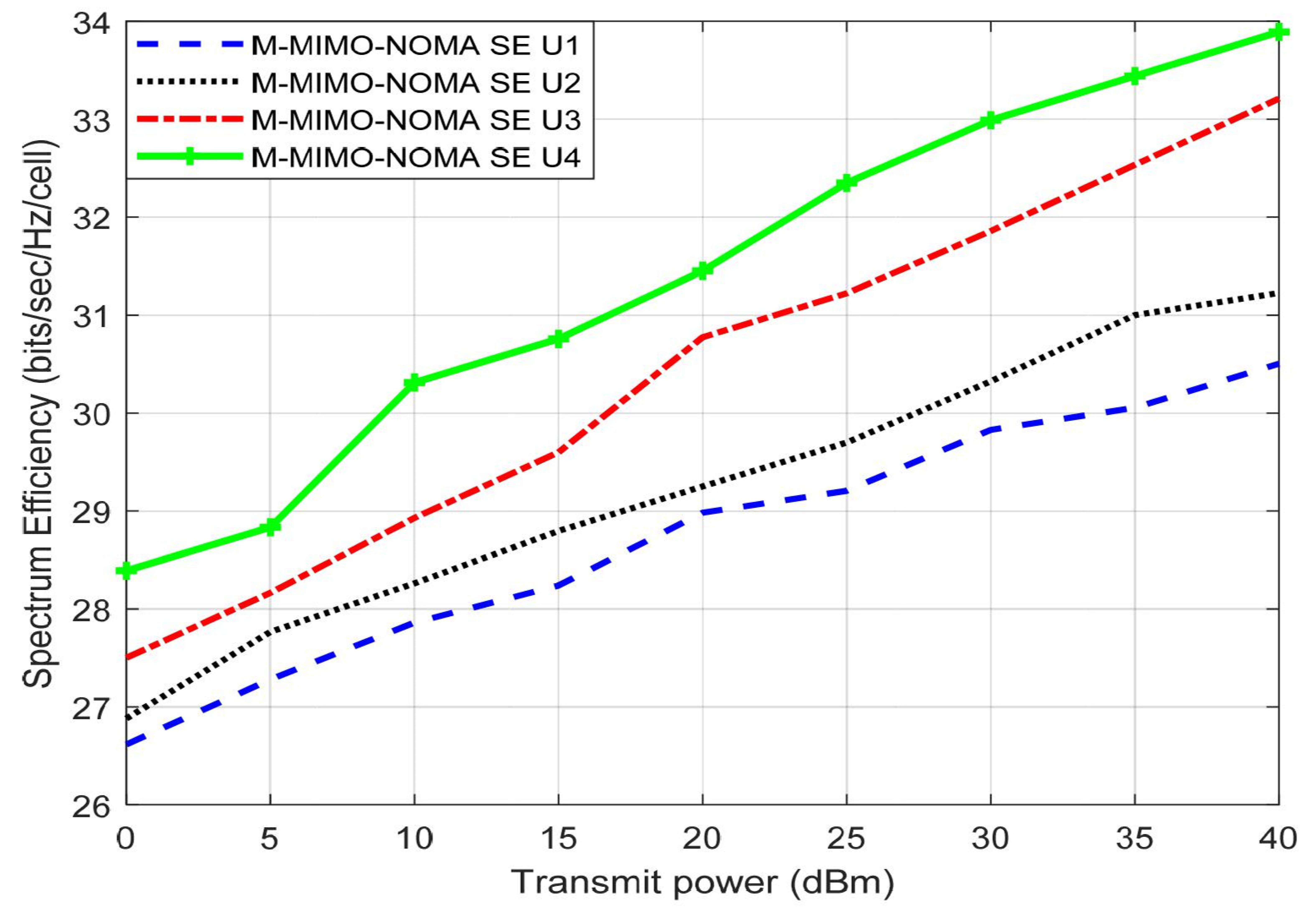
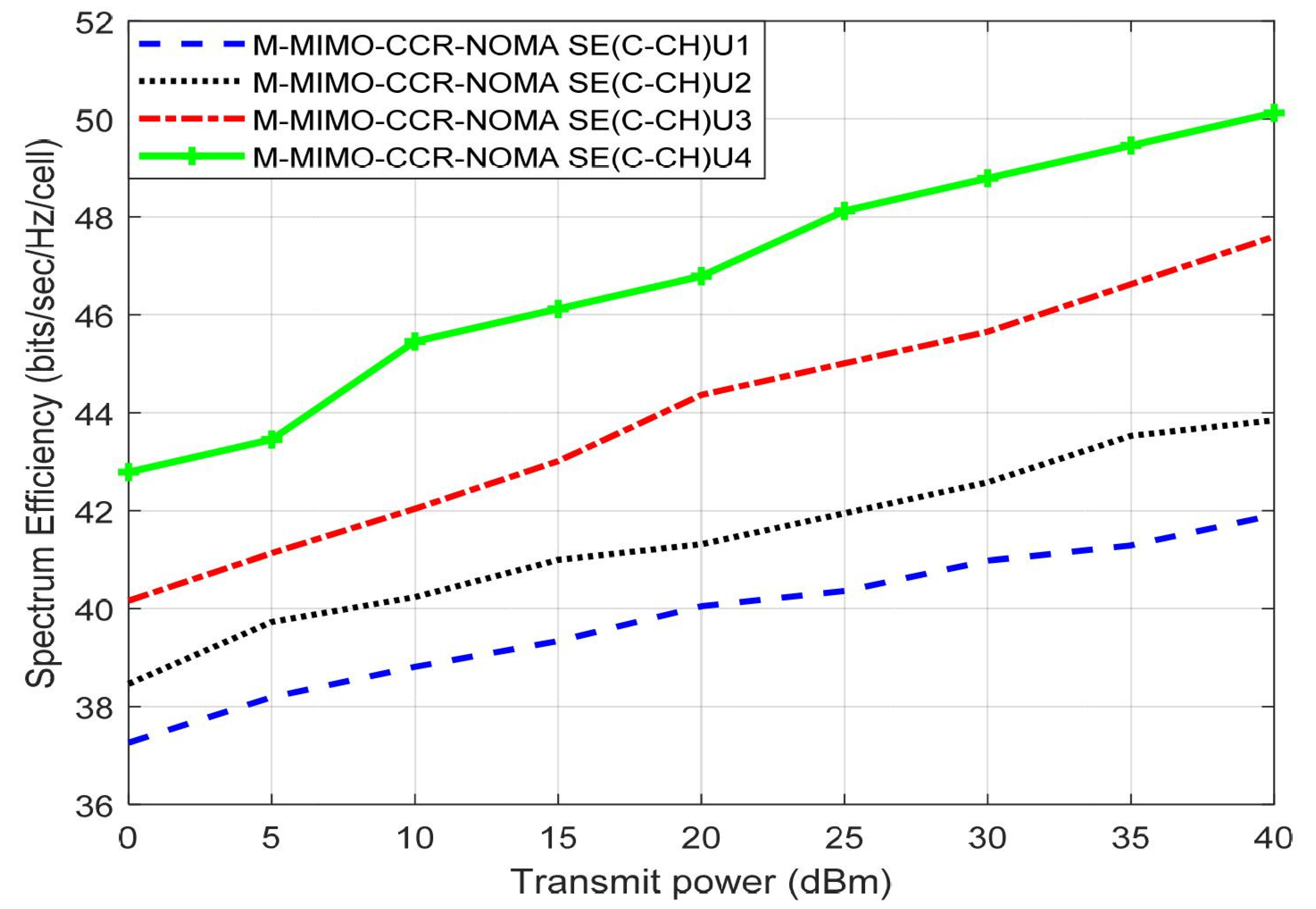
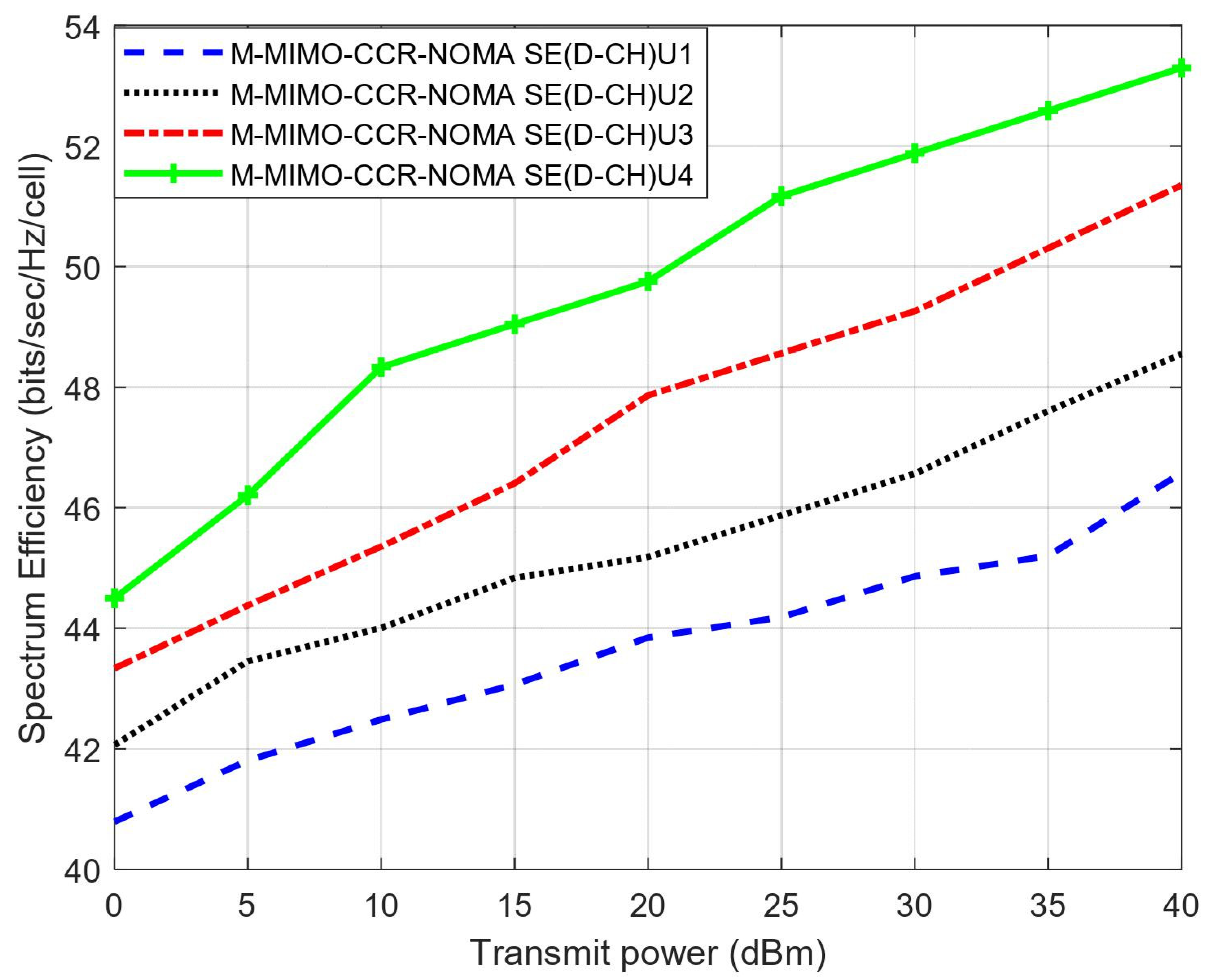
4.3. M-MIMO DL NOMA PD
5. Conclusions
Author Contributions
Funding
Data Availability Statement
Acknowledgments
Conflicts of Interest
References
- Ding, Z.; Lei, X.; Karagiannidis, G.; Schober, R. A Survey on Non-Orthogonal Multiple Access For 5g Networks: Research Challenges and Future Trends. IEEE J. Sel. Areas Commun. 2017, 35, 2181–2195. [Google Scholar] [CrossRef]
- Hassan, M.; Singh, M.; Hamid, K. Review of NOMA with Spectrum Sharing Technique. In ICT with Intelligent Applications. Smart Innovation; Systems and Technologies; Senjyu, T., Mahalle, P.N., Perumal, T., Joshi, A., Eds.; Springer: Singapore, 2022; Volume 248. [Google Scholar]
- Ding, Z. Application of Non-Orthogonal Multiple Access in LTE and 5G Networks. IEEE Commun. Mag. 2017, 55, 185–191. [Google Scholar] [CrossRef]
- Hassan, M.; Singh, M.; Hamid, K. Survey on NOMA and Spectrum Sharing Techniques in 5G. In Proceedings of the IEEE International Conference on Smart Information Systems and Technologies (SIST), Nur-Sultan, Kazakhstan, 28–30 April 2021; pp. 1–4. [Google Scholar]
- Dai, L.; Wang, B.; Ding, Z. A Survey of Non-Orthogonal Multiple Access For 5G. IEEE Commun. Surv. Tutor. 2018, 20, 2294–2323. [Google Scholar] [CrossRef]
- Makki, B.; Chitti, K.; Behravan, A.; Alouini, M. A Survey of Noma: Current Status and Open Research Challenges. IEEE Open J. Commun. Soc. 2020, 1, 179–189. [Google Scholar] [CrossRef]
- Balasubramanya, N.; Gupta, A.; Sellathurai, M. Combining Code-Domain and Power-Domain NOMA for Supporting Higher Number of Users. In Proceedings of the IEEE Global Communications Conference (GLOBECOM), Abu Dhabi, United Arab Emirates, 9–13 December 2018; pp. 1–6. [Google Scholar]
- Marcano, A.; Christiansen, H. A Novel Method for Improving the Capacity in 5G Mobile Networks Combining NOMA and OMA. In Proceedings of the IEEE 85th Vehicular Technology Conference (VTC Spring), Sydney, Australia, 4–7 June 2017. [Google Scholar]
- Arzykulov, S.; Nauryzbayev, G.; Tsiftsis, T. Error Performance of Wireless Powered Cognitive Relay Networks with Interference Alignment. In Proceedings of the IEEE 28th Annual International Symposium on Personal, Indoor, and Mobile Radio Communications (PIMRC), Montreal, QC, Canada, 8–13 October 2017; pp. 1–5. [Google Scholar]
- Arzykulov, S.; Tsiftsis, T.; Nauryzbayev, K. Outage Performance of Underlay CR-Noma Networks with Detect-and-Forward Relaying. In Proceedings of the IEEE Global Communications Conference (GLOBECOM), Abu Dhabi, United Arab Emirates, 9–13 December 2018; pp. 1–6. [Google Scholar]
- Hassan, M.; Singh, M.; Hamid, K. Overview of Cognitive Radio Networks. J. Phys. Conf. Ser. 2020, 1831, 012013. [Google Scholar] [CrossRef]
- Hu, F.; Zhu, K. Full Spectrum Sharing in Cognitive Radio Networks Toward 5g: A Survey. IEEE Access 2018, 6, 15754–15776. [Google Scholar] [CrossRef]
- Hassan, M.; Singh, M.; Hamid, K. Survey on Advanced Spectrum Sharing Using Cognitive Radio Technique. Adv. Intell. Syst. Comput. 2021, 1270, 639–647. [Google Scholar]
- Balachander, T.; Krishnan, T. Efficient Utilization of Cooperative Spectrum Sensing (CSS) In Cognitive Radio Network (CRN) Using Non-Orthogonal Multiple Access (Noma). Wirel. Pers Commun 2021, 127, 2189–2210. [Google Scholar] [CrossRef]
- Do, D.-T.; Le, A.-T.; Lee, B.M. NOMA In Cooperative Underlay Cognitive Radio Networks Under Imperfect Sic. IEEE Access 2020, 8, 86180–86195. [Google Scholar] [CrossRef]
- Thakur, P.; Singh, G. Spectral Efficient Designs of MIMO-Based CR-NOMA For Internet of Things Networks. Int. J. Commun. Syst. 2021, 34, 4888–4900. [Google Scholar] [CrossRef]
- Manimekalai, T.; Romera, S.; Laxmikandan, T. Throughput Maximization for Underlay CR Multicarrier NOMA Network with Cooperative Communication. ETRI J. 2020, 42, 846–858. [Google Scholar] [CrossRef]
- Li, X.; Gao, X.; Shaikh, S.; Ming, Z.; Huang, G. NOMA-Based Cognitive Radio Network with Hybrid FD/HD Relay in Industry 5.0. J. King Saud Univ. 2022, 1319–1578. [Google Scholar] [CrossRef]
- Zuo, Y.; Zhu, X.; Jiang, Y.; Wei, Z.; Zeng, H.; Wang, T. Energy Efficiency and Spectral Efficiency Tradeoff for Multicarrier Noma Systems with User Fairness. In Proceedings of the IEEE/CIC International Conference on Communications in China (ICCC), Beijing, China, 16–18 August 2018; pp. 666–670. [Google Scholar]
- Tang, K.; Liao, S. Outage Analysis of Relay-Assisted Noma in Cooperative Cognitive Radio Networks with Swipt. Information 2020, 11, 500. [Google Scholar] [CrossRef]
- Lin, Z.; Niu, H.; An, K.; Wang, Y.; Zheng, G.; Chatzinotas, S.; Hu, Y. Refracting RIS-Aided Hybrid Satellite-Terrestrial Relay Networks: Joint Beamforming Design and Optimization. IEEE Trans. Aerosp. Electron. Syst. 2022, 58, 3717–3724. [Google Scholar] [CrossRef]
- Lin, Z.; Lin, M.; Wang, J.B.; de Cola, T.; Wang, J. Joint Beamforming and Power Allocation for Satellite-Terrestrial Integrated Networks With Non-Orthogonal Multiple Access. IEEE J. Sel. Top. Signal Process. 2019, 13, 657–670. [Google Scholar] [CrossRef]
- Lin, Z.; An, K.; Niu, H.; Hu, Y.; Chatzinotas, S.; Zheng, G.; Wang, J. SLNR-based Secure Energy Efficient Beamforming in Multibeam Satellite Systems. IEEE Trans. Aerosp. Electron. Syst. 2022, 1–4. [Google Scholar] [CrossRef]
- Niu, H.; Lin, Z.; Chu, Z.; Zhu, Z.; Xiao, P.; Nguyen, H.X.; Lee, I.; Al-Dhahir, N. Joint Beamforming Design for Secure RIS-Assisted IoT Networks. IEEE Internet Things J. 2023, 10, 1628–1641. [Google Scholar] [CrossRef]
- Wang, X.; Cheng, J.; Zhai, C.; Ashikhmin, A. Partial Cooperative Zero-Forcing Decoding for Uplink Cell-Free Massive MIMO. IEEE Internet Things J. 2022, 9, 10327–10339. [Google Scholar] [CrossRef]
- Gamal, S.; Rihan, M.; Hussin, S.; Zaghloul, A.; Salem, A.A. Multiple Access in Cognitive Radio Networks: From Orthogonal and Non-Orthogonal to Rate-Splitting. IEEE Access 2021, 9, 95569–95584. [Google Scholar] [CrossRef]
- Hamdi, M. Downlink Scheduling in 5G Massive MIMO. J. Eng. Appl. Sci. 2018, 13, 1376–1381. [Google Scholar]
- Hassan, M.; Singh, M.; Hamid, K. BER Performance of NOMA Downlink for AWGN and Rayleigh Fading Channels In (Sic). EAI Endorsed Trans. Mob. Com. Appl. 2022, 7. [Google Scholar] [CrossRef]
- Dinh, S.; Liu, H.; Ouyang, F. Massive MIMO Cognitive Cooperative Relaying. In Wireless Algorithms, Systems, and Applications. WASA. Lecture Notes in Computer Science; Biagioni, E., Zheng, Y., Cheng, S., Eds.; Springer: Berlin/Heidelberg, Germany, 2019; Volume 11604. [Google Scholar]
- Chen, K.; Prasad, R. Cognitive Radio Networks, 1st ed.; Wiley & Sons: Hoboken, NJ, USA, 2009; pp. 183–216. [Google Scholar]
- Hassan, M.; Singh, M.; Hamid, K.; Saeed, R.; Abdelhaq, M.; Alsaqour, R. Modeling of Noma-MIMO-Based Power Domain for 5g Network Under Selective Rayleigh Fading Channels. Energies 2022, 15, 5668. [Google Scholar] [CrossRef]
- Liu, Y.; Pan, G.; Zhang, H.; Song, M. On the Capacity Comparison Between MIMO-NOMA and MIMO-OMA. IEEE Access 2016, 4, 2123–2129. [Google Scholar] [CrossRef]
- Zeng, M.; Yadav, A.; Dobre, O.A.; Tsiropoulos, G.I.; Poor, H.V. Capacity Comparison Between MIMO-NOMA and MIMO-OMA With Multiple Users in a Cluster. IEEE J. Sel. Areas Commun. 2017, 35, 2413–2424. [Google Scholar] [CrossRef]
- Amin, A.A.; Shin, S.Y. Capacity Analysis of Cooperative NOMA-OAM-MIMO Based Full-Duplex Relaying for 6G. IEEE Wirel. Commun. Lett. 2021, 10, 1395–1399. [Google Scholar] [CrossRef]
- Shen, D.; Wei, C.; Zhou, X.; Wang, L.; Xu, C. Photon Counting Based Iterative Quantum Non-Orthogonal Multiple Access with Spatial Coupling. In Proceedings of the 2018 IEEE Global Communications Conference (GLOBECOM), Abu Dhabi, United Arab Emirates, 9–13 December 2018; pp. 1–6. [Google Scholar]
- Hassan, M.B.; Ali, E.S.; Rashid, A. Ultra-Massive MIMO in THz Communications. In Next Generation Wireless Terahertz Communication Networks; CRC Group: Boca Raton, FL, USA; Taylor & Francis Group: London, UK, 2020. [Google Scholar] [CrossRef]
- Rehman, B.U.; Babar, M.I.; Azim, G.A.; Amir, M.; Alhumyani, H.; Alzaidi, M.S.; Alshammari, M.; Saeed, R. Uplink power control scheme for spectral efficiency maximization in NOMA systems. Alex. Eng. J. 2023, 64, 667–677. [Google Scholar] [CrossRef]
- Rehman, B.U.; Babar, M.I.; Ahmad, A.W.; Alhumyani, H.; Azim, G.A.; Saeed, R.A.; Khalek, S.A. Joint power control and user grouping for uplink power domain non-orthogonal multiple access. Int. J. Distrib. Sens. Netw. 2021, 17. [Google Scholar] [CrossRef]


| No. | Parameters | Values | |
|---|---|---|---|
| 1. | Number of users | ||
| 2. | Transmit power | ||
| 3. | Bandwidth | BW | |
| 4. | Distances | U1 | |
| U2 | |||
| U3 | |||
| U4 | |||
| 5. | Power coefficients | U1 | |
| U2 | |||
| U3 | |||
| U4 | |||
| 6. | Path loss exponent | 4 | |
| 7. | SISO | ||
| 8. | MIMO | ||
| 9. | M-MIMO | ||
| 10. | Modulation | QPSK | |
Disclaimer/Publisher’s Note: The statements, opinions and data contained in all publications are solely those of the individual author(s) and contributor(s) and not of MDPI and/or the editor(s). MDPI and/or the editor(s) disclaim responsibility for any injury to people or property resulting from any ideas, methods, instructions or products referred to in the content. |
© 2023 by the authors. Licensee MDPI, Basel, Switzerland. This article is an open access article distributed under the terms and conditions of the Creative Commons Attribution (CC BY) license (https://creativecommons.org/licenses/by/4.0/).
Share and Cite
Hassan, M.; Singh, M.; Hamid, K.; Saeed, R.; Abdelhaq, M.; Alsaqour, R.; Odeh, N. Enhancing NOMA’s Spectrum Efficiency in a 5G Network through Cooperative Spectrum Sharing. Electronics 2023, 12, 815. https://doi.org/10.3390/electronics12040815
Hassan M, Singh M, Hamid K, Saeed R, Abdelhaq M, Alsaqour R, Odeh N. Enhancing NOMA’s Spectrum Efficiency in a 5G Network through Cooperative Spectrum Sharing. Electronics. 2023; 12(4):815. https://doi.org/10.3390/electronics12040815
Chicago/Turabian StyleHassan, Mohamed, Manwinder Singh, Khalid Hamid, Rashid Saeed, Maha Abdelhaq, Raed Alsaqour, and Nidhal Odeh. 2023. "Enhancing NOMA’s Spectrum Efficiency in a 5G Network through Cooperative Spectrum Sharing" Electronics 12, no. 4: 815. https://doi.org/10.3390/electronics12040815
APA StyleHassan, M., Singh, M., Hamid, K., Saeed, R., Abdelhaq, M., Alsaqour, R., & Odeh, N. (2023). Enhancing NOMA’s Spectrum Efficiency in a 5G Network through Cooperative Spectrum Sharing. Electronics, 12(4), 815. https://doi.org/10.3390/electronics12040815