Abstract
The creation of multiple applications with a higher level of complexity has been made possible by the usage of artificial neural networks (ANNs). In this research, an efficient flexible finite impulse response (FIR) filter structure called ADALINE (adaptive linear element) that makes use of a MAC (multiply accumulate) core is proposed. The least mean square (LMS) and recursive least square (RLS) algorithms are the most often used methods for maximizing filter coefficients. Despite outperforming the LMS, the RLS approach has not been favored for real-time applications due to its higher design arithmetic complexity. To achieve less computation, the fundamental filter has utilized an LMS-based tapping delay line filter, which is practically a workable option for an adaptive filtering algorithm. To discover the undiscovered system, the adjustable coefficient filters have been developed in the suggested work utilizing an optimal LMS approach. The 10-tap filter being considered here has been analyzed and synthesized utilizing field programmable gate array (FPGA) devices and programming in hardware description language. In terms of how well the resources were used, the placement and postrouting design performed well. If the implemented filter architecture is compared with the existing filter architecture, it reveals a 25% decrease in resources from the existing one and an increase in clock frequency of roughly 20%.
1. Introduction
This research focuses on applications of signal processing, such as channel equalization, acoustic echo removal, speech recognition, and blind source separation. Filters are the main source used for removing unwanted data from a signal, eliminating background noise and extracting useful information for subsequent analysis. There are two types of filters: analog and digital. Digital filters can be quickly reconfigured, have a small footprint, and are highly effective. When compared with their analog counterparts, digital filters offer greater precision. Both finite FIR and IIR digital filters are common. In most cases, FIR filters are efficient to implement, have a low number of finite precision errors, and are stable and linear in phase. The computational complexity is higher than that of an IIR filter by a significant margin [1]. Additionally, there is a reduction in the number of coefficients and the amount of space needed for an IIR filter. Furthermore, because they are more similar to analogue models, IIR filters have superior magnitude responses. As a result, fewer multiplier units are needed to implement an IIR filter instead of an FIR filter. As such, IIR filters find widespread application in high-speed systems. Unlike analogue filters, digital IIR filters do not share their frequency response with those of the analogue variety. Moreover, IIR notch filters are unreliable [2] when the interference signal’s frequency varies. Furthermore, IIR filters consist of a feedback loop, which, when implemented with an adaptive filter, causes further delay and creates hardware complexity. Another way to speed up the process is by using pipelining; high speed is provided by a pipelined architecture for normalized least mean squares (NLMS) adaptive filters [3,4]. Furthermore, adaptive filters can also be used for artifact removal [5,6]. All filters have multipliers, and when the input increases, the multipliers also increase. Considering the disadvantages in addition to the advantages, we have developed a novel active noise cancellation system based on a neural network, called ADALINE with single time-sharing MAC. This has been synthesized using an FPGA. In an adaptive FIR filter architecture, the direct implementation of an N-tap FIR filter requires N-MAC operations. These operations are difficult to compute due to their hardware complexity and the amount of space they require. The ADALINE filter architecture is implemented using a time-sharing multiplier architecture throughout a pipelined-based single MAC core regardless of the number of taps. This is performed to overcome the limits discussed above. The concept of time sharing only appears in the filtering section of existing systems. Recently, many nonlinear methods based on neural networks have been created to produce various FIR filter types [7]. For adaptive noise cancellation in this study, we chose an ADALINE because of its straightforward structure and bias component, which increases the convergence rate [8]. To evaluate performance when altering audio recording parameters, this study offers a noise canceller implementation example utilizing an ADALINE network. Additionally, synaptic weights are examined to gauge how well an adaptive filter works. Every system has a flaw in that noise may be inadvertently added during acquisition operations, resulting in inaccuracies in the processing of digital signals, delays in the right equipment’s operation, irritation to users, and other unanticipated concerns. ANNs offer an interesting solution to this problem, which is made possible by a unique configuration of the ADALINE network. An ADALINE is chosen for noise cancellation based on its ability to function as an adaptive filter and the fast-processing speed it can provide. ADALINE is undoubtedly a method worth researching given that it is now the neural network methodology that is most frequently used in practical applications [9]. Its rapid processing performance is aided by its simple network architecture and low component count. Comparing the performance of the ADALINE system with that of other systems is the most effective technique to evaluate its performance. This research is to implement ADALINE with the MAC architecture. MAC is the architecture used in signal processing applications with multipliers. Reducing the number of multipliers is also necessary to reduce resource complexity [10,11]. Therefore, it is necessary to create an architecture that goes beyond the aforementioned limitations. In this proposed architecture, error computation of weight update block (LMS algorithm) is performed with parallel MAC architecture with pipelining to maximize the speed. This was performed to optimize the speed. Using a time-sharing technique for a 10-tap adaptive FIR filter, the block that handles error computation and weight updating requires just 13 multipliers according to the design that has been proposed here. When combined with ADALINE, the architecture’s complexity is reduced, and its speed is increased. The effectiveness of the suggested architectures in terms of time and space is examined. The results are validated using an approach called FPGA in the loop (FIL). This paper is divided into the following sections: Section 2 describes ADALINE neural networks, and Section 3 explains MAC. The MAC architecture is discussed in Section 4 along with the activation function of ADALINE. Section 5 presents the results and discussion, and Section 6 concludes the work.
2. ADALINE
Every system in the world has the drawback of having a noise that can be added unintentionally during acquisition operations, leading to errors in digital signal processing, delays in the operation of the right devices, inconvenience to users, and other unforeseen issues. Because of this, artificial neural networks offer an intriguing approach to solving the problem [12]. To enable this procedure, a particular configuration of the ADAptive LINear Element Network is used; this configuration is also known as an adaptive filter. It is feasible to construct many applications, such as the design of active power filters, the control of wind speed forecasts, and fetal ECG extraction, using the adaptive filter structure of the proposed work. The fundamental problem with using normal filters is that they do not work for nonlinear systems; in this case, mathematical modeling of adaptive filter construction removes this limitation in developing applications. ADALINE is the name of one of the essential models for signal processing and data prediction. Similar to perceptrons, ADALINE networks’ outputs can take on any value, as opposed to the perceptron’s output, which can only be either 0 or 1. Only linearly separable issues can be resolved by ADALINE and the perceptron. Nevertheless, this study uses the least mean squares learning rule, which is far more effective than the perceptron learning rule. The Widrow–Hoff learning rule, often known as the LMS, moves the decision boundaries as far away from the training patterns as possible by minimizing mean square error [13,14]. A processing unit’s ability to adjust its input/output behavior in response to changes in the environment is implied by the fact that ANNs are sophisticated adaptive systems. The fixed activation function and input/output vector that is used when a specific network is built increase the significance of learning in ANNs. We must now modify the weights to alter the input/output behavior.
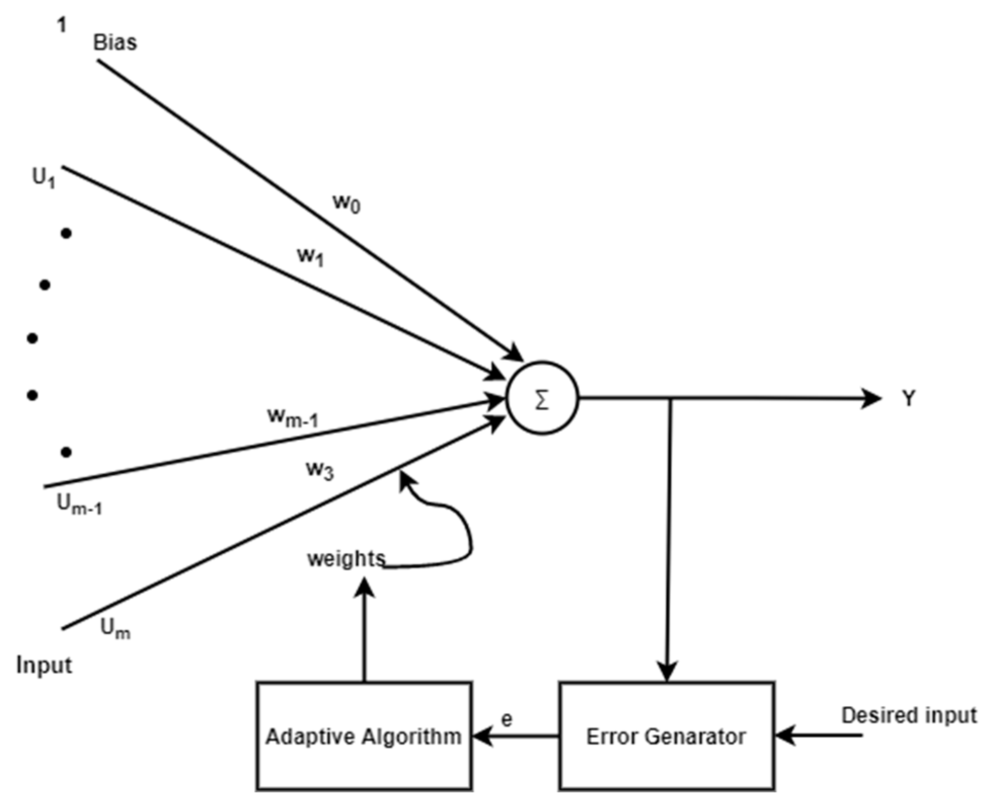
The basic structure of ADALINE is shown in Figure 1, where the output depends on bias and weight. The same structure can be replaced with neural networks, as shown in Figure 2.

Figure 1.
Linear neurons with m input.
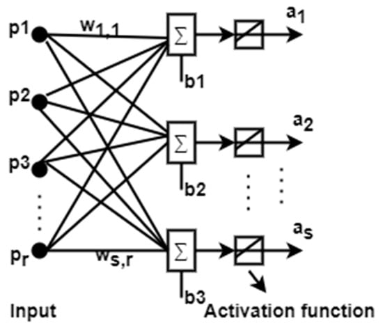
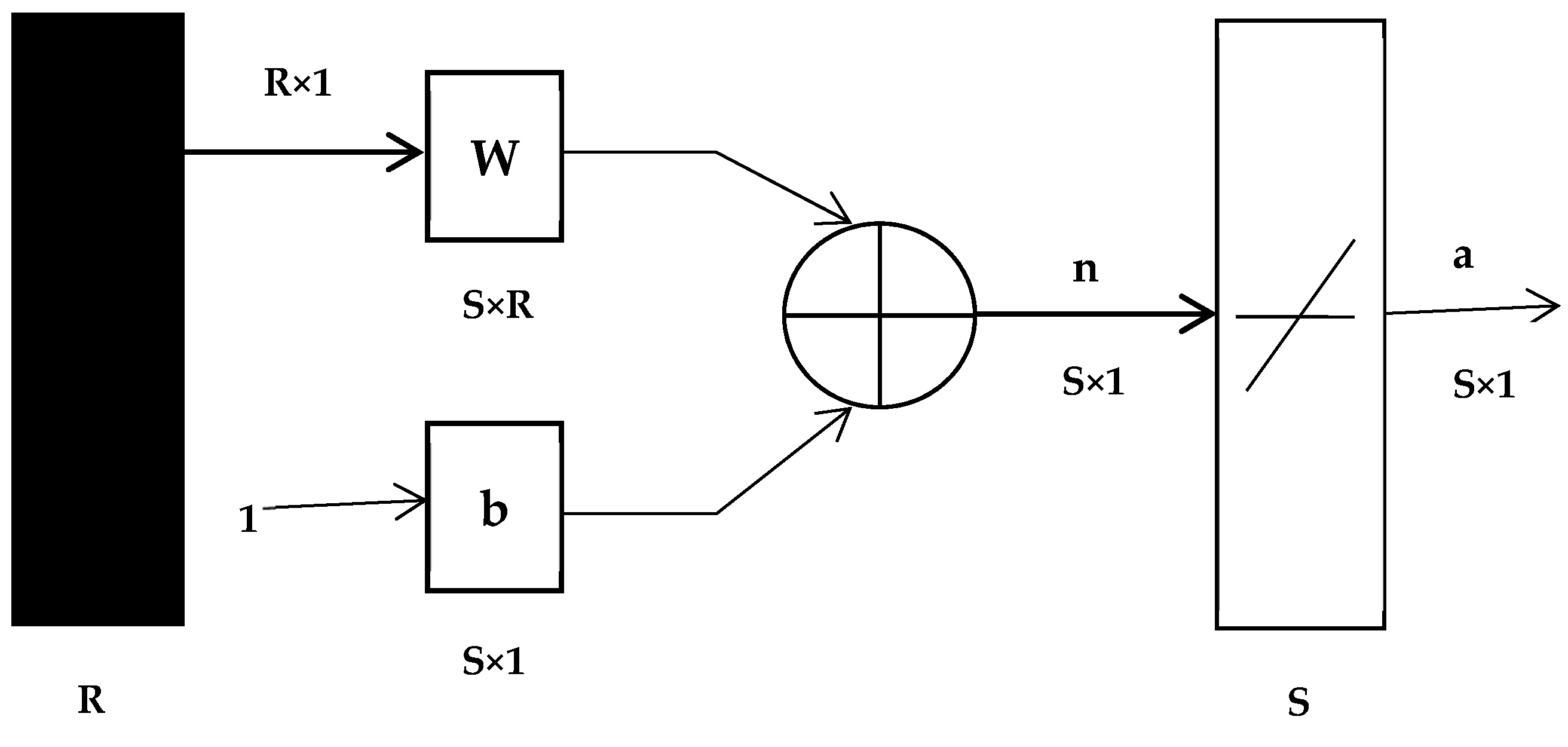
Figure 2.
MADALINE (Many ADAptive LINear Elements).
ADALINE networks are sometimes called MADALINE when the input neuron increases, and the structure of MADALINE is shown in Figure 2. In the MADALINE network, a W matrix of weights connects the inputs from R to one layer of S neurons.
Ted Hoff and Bernie Widrow invented the ADALINE network (see Figure 3). ADALINE contains “purelin” linear function transfer, whereas perceptron (“hardlin”) serves as a classifier for this type of transfer function, which is not similar.

Figure 3.
ADALINE network configuration.
The output of the ADALINE network is calculated by
The same in the iteration form can be given as
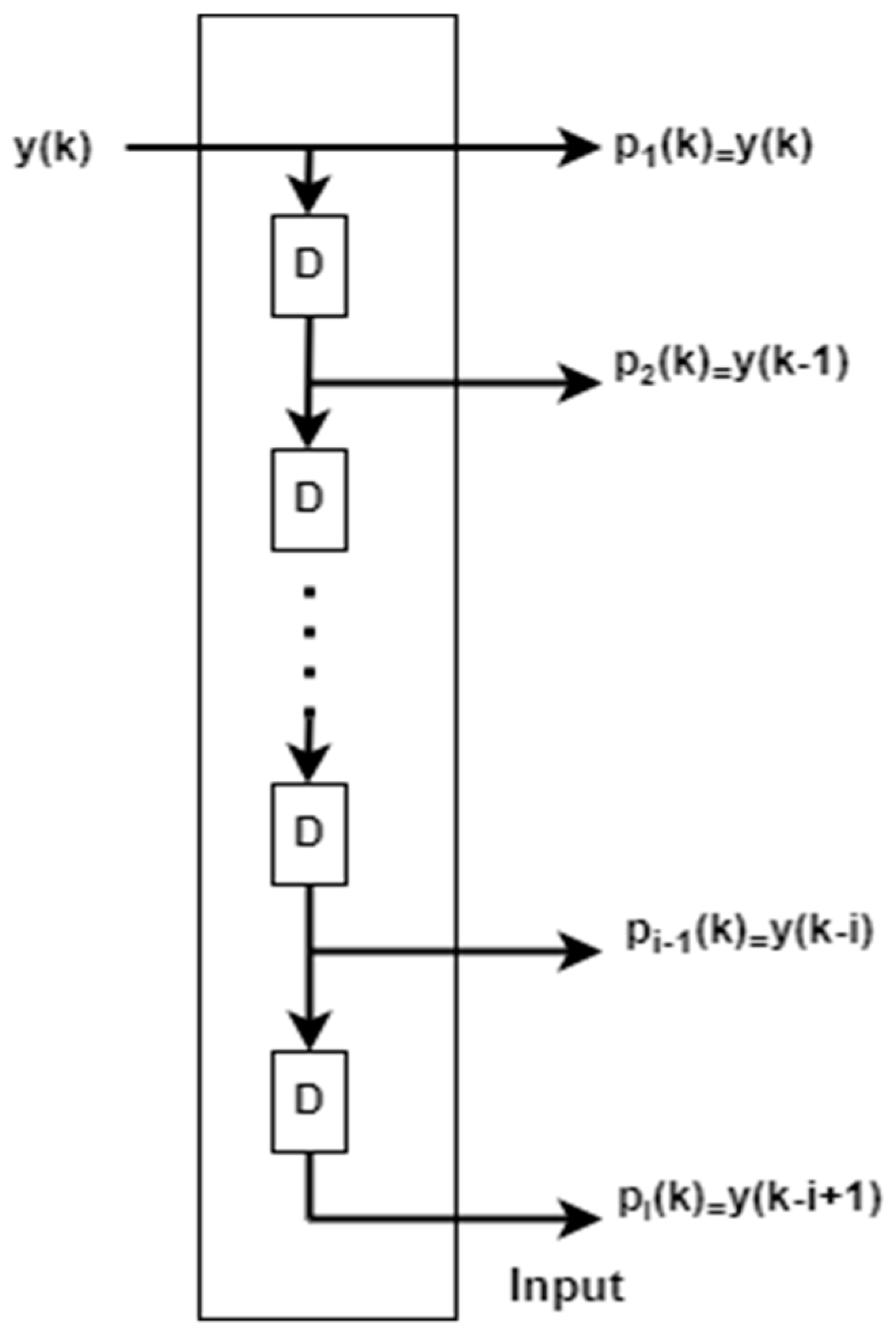
Tapped delay line structure is shown in Figure 4. This can be added with the conventional ADALINE network to make an adaptive filter in the first tap since there is no delay, after each tapped delay , will be increased accordingly.

Figure 4.
Structure of tapped delay line.
The Widrow–Hoff rule is only capable of training single-layer linear networks. This can also be prepared for multilayer networks by incorporating a single linear network with proper delay elements, as indicated in Figure 5. Below, an adaptive filter can be made by combining a taped delay and an ADALINE network.
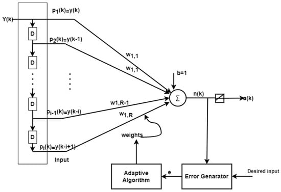
Figure 5.
ADALINE as an adaptive filter.
For the above adaptive filter, the output function is given as
where “y(k)” is the input signal and i represents the delay line count. Mean square error is minimized by updating the weight, bias, and error until the desired error using the least mean square approach (LMS) and steepest descent method. To calculate the mean square error, Widrow and Hoff’s Equation (4) is employed.
Equation (5) is produced if the gradient estimate was obtained.
Equation (5) can be expanded with derivatives to weights.
Substituting Equation (4) in (6),
Changing the above equation in iteration form
A similar process for bias updation is given as
By this, weight and bias updation is given in simplified form as
The steepest descent algorithm states that
Rearranging the above equations with the relation of , it is possible to obtain the updated weight and bias, which can be used further for adaptive filter.
Equations (15) and (16) are the updated weight and bias, which is to be added with the ADALINE filter.
3. General Construction of MAC
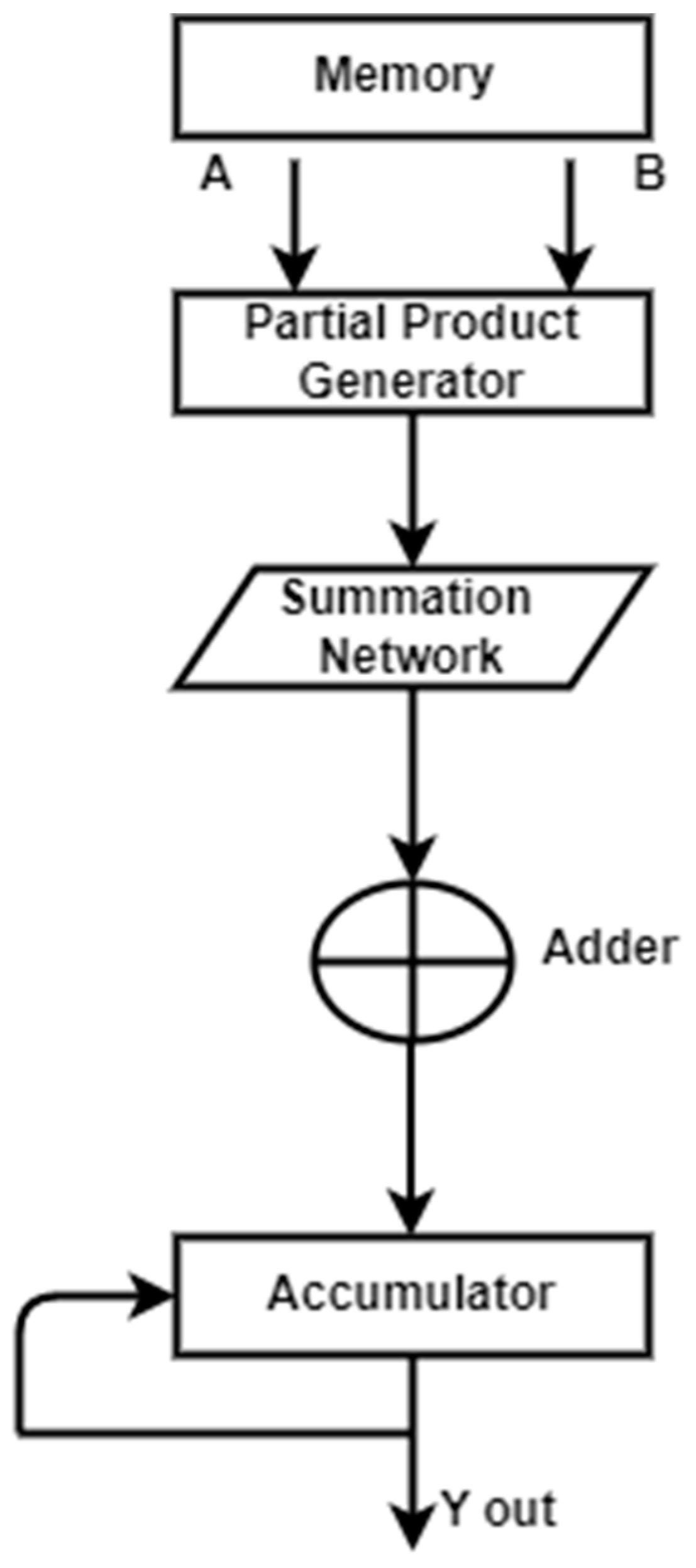
A fundamental step in computing, particularly for applications involving digital signal processing, is the multiplication and accumulation process. At this point, an accumulator is added along with the calculation of the product of two values. This procedure is carried out by a hardware component of the digital signal processor known as a multiplier–accumulator. The MAC unit, which is constantly on the critical path, controls the system’s overall speed. Real-time DSP applications require the development of a quick MAC. Due to the growing need for wireless sensor networks, MAC devices that consume low power will surely dominate the market. To boost the speed of the MAC unit, two key bottlenecks must be considered. The partial product reduction network, which is employed in the multiplication block, is the first, and the accumulator is the second. A typical operation called “multiply–accumulate” computes the sum of two numbers and adds that sum to an accumulator. The general structure of MAC is depicted in Figure 6.

Figure 6.
The general structure of MAC.
The multiplier is made up of three parts: an adder, a summing network, and a partial product generator (PPG). The summing network, which divides the total number of partial products into two operands, a sum and a carry, is the heart of the MAC unit. The summation network occupies the majority of the circuit area and latency. To best implement, the summation network, numerous algorithms, and topologies are suggested. The multiplication result is subsequently produced using these two operands by the last adder. The result of the multiplication is added with double precision using the accumulator and the accumulated operand. The accumulator requires a very large adder since the operand size is so large.
4. MAC-Based ADALINE Filter
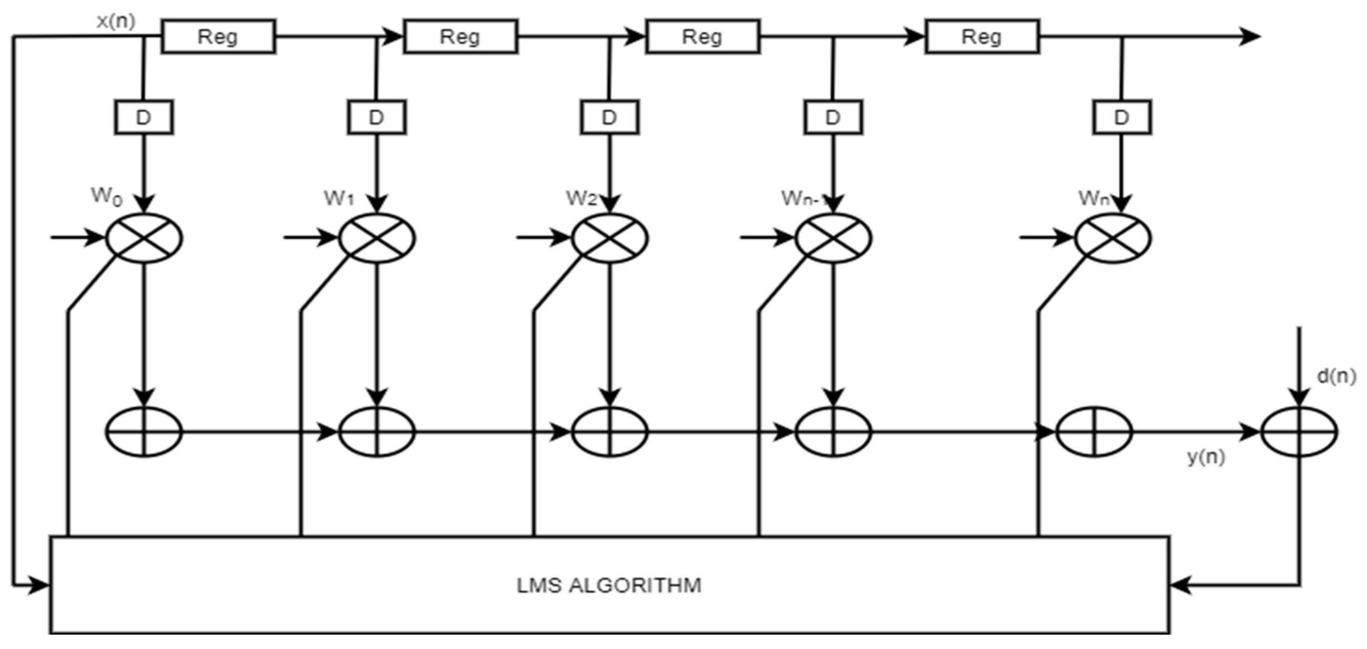
The conventional adaptive filter in this Figure 7. The number of multipliers will also increase according to the number of multipliers. Which will further increase the hardware requirements.

Figure 7.
The conventional adaptive architecture.
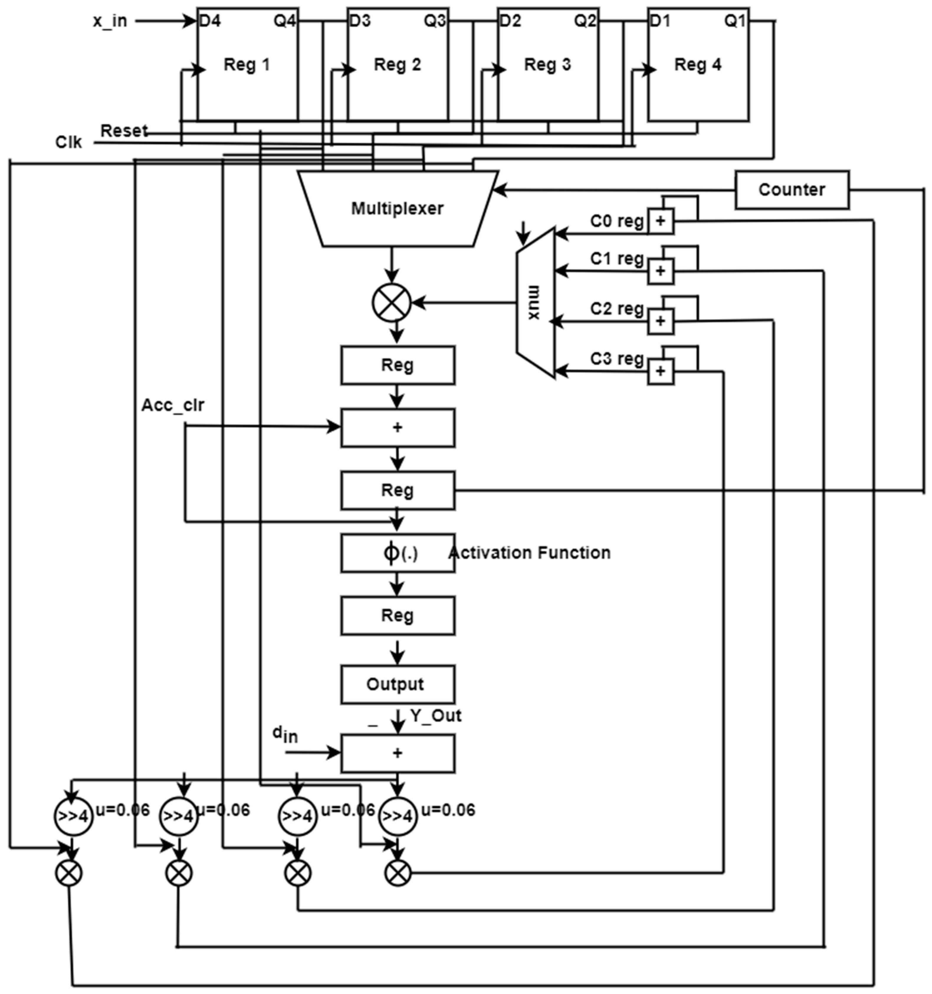
In existing systems, delays are inserted to make the process sequential, resulting in slower speeds and larger FPGA implementations. To overcome this resource complexity, this proposed work is implemented with a single MAC ADALINE filter, where many multipliers are replaced with a single multiplier, and the product is shifted to the accumulator accordingly. Figure 8 depicts the proposed construction of a single MAC-ADALINE filter. This proposed architecture can be split into two different blocks: an error computational block and a weight update block. The error computational block can also be known as the filter block. The weight update block consists of a pipelined-based single MAC algorithm with an existing LMS architecture. Clock cycles are used to complete the filter operation; for a 10-tap filter, 10 clock cycles are required to compute the filter operation. For every clock cycle, one data is inserted, and the output is taken for every clock cycle. To select the data across the registers, multipliers are used and the select line for the 4:1 mux is assigned by the counter. Once the filter coefficients have been stored in registers, a multiplexer is used to pick up the data from the registers and perform the multiplier operation. The accumulation block, which is used to multiply the previous data value by the present data value, is reset to zero after two clock cycles. The input will be given to the activation function like the ADALINE operation. This activation function will be active only with the updated weight and bias values. A multiplexer selecting pick lines and an accumulator action are limited to one generic counter, and the error signal is the difference between the filter output and the desired signal (din), which is returned to the input (Y out). The warning symbol updates the filter coefficients c0 reg and c1 reg, c2 reg, and c3 reg at the same time. The outcome is multiplied by x_in with a step index of 0.06 before being added to the output.
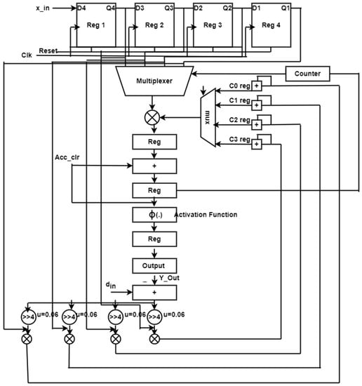
Figure 8.
Single MAC ADALINE filter.
5. Result and Discussion
The suggested designs were assembled and synthesized using Altera Cyclone IV4CE115F23C7 and Xilinx Virtex-5 FPGA. The Altera DE2-115 and the Matlab Simulink tool are used to test the model’s performance for real-time operations using FPGA in a loop.
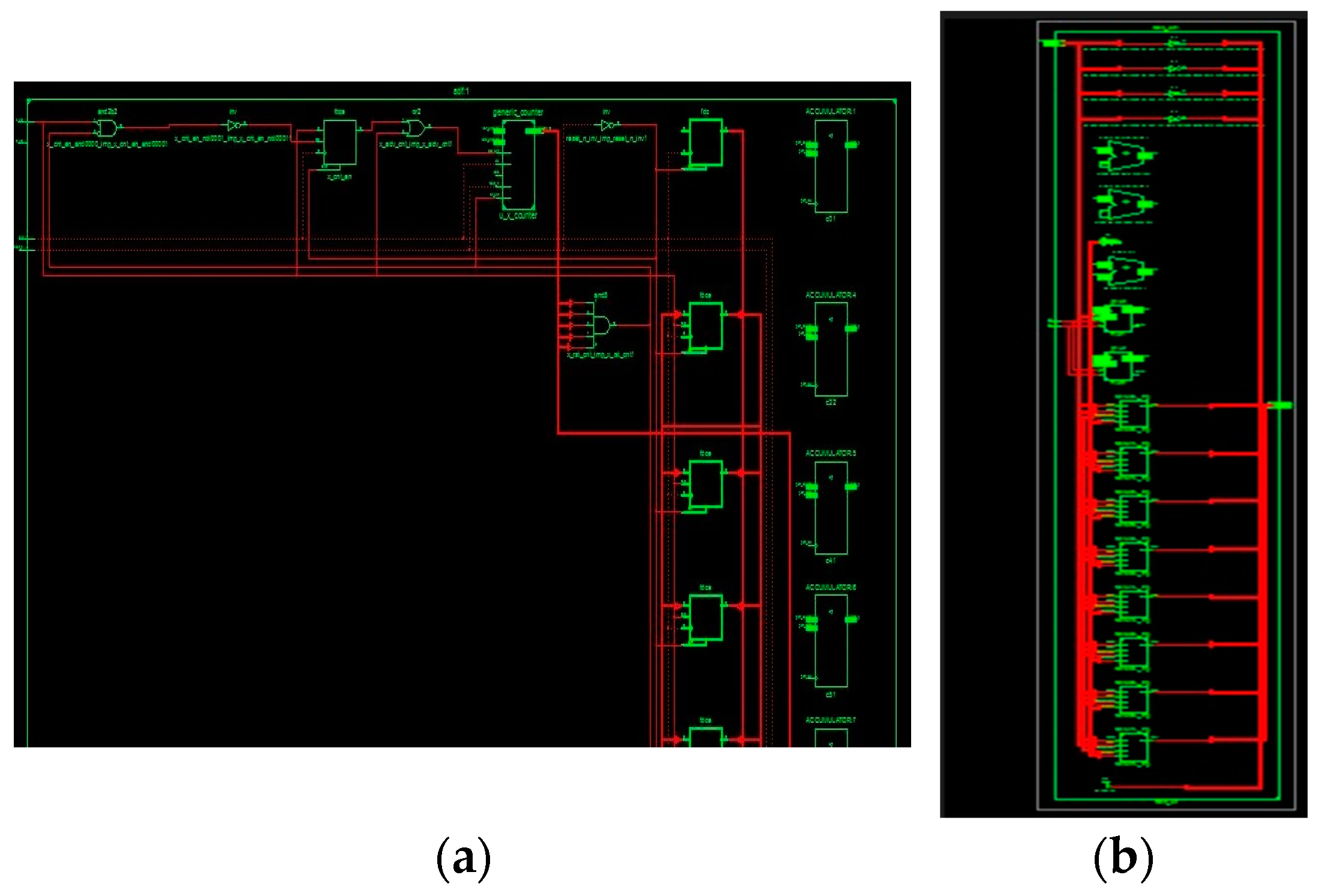
The simulated waveform of an adaptive FIR filter is depicted in Figure 9. In the diagram, x_in and x_val are input signals; d_in and d_out are the desired signals; and the filter output and error output are y_out and e_out, respectively. The adaptive FIR filter output, y_out, is obtained at 125 ns after processing input signals for a six-cycle delay at an 80 ns processing time, and it is displayed in the MAC output. These architectures use a time division multiplier to implement single MAC-based filter sections. Figure 10 shows the RTL schematic diagram activation function and a schematic diagram of the ADALINE filter.
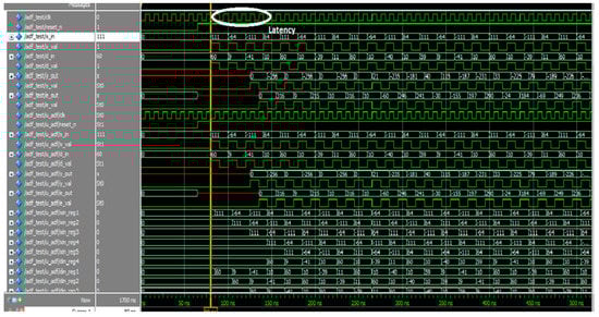
Figure 9.
Figure simulation waveform of proposed single MAC ADALINE filter.

Figure 10.
RTL schematic diagram of the (a) time-sharing single MAC ADALINE filter and (b) parallel MAC-based LMS.
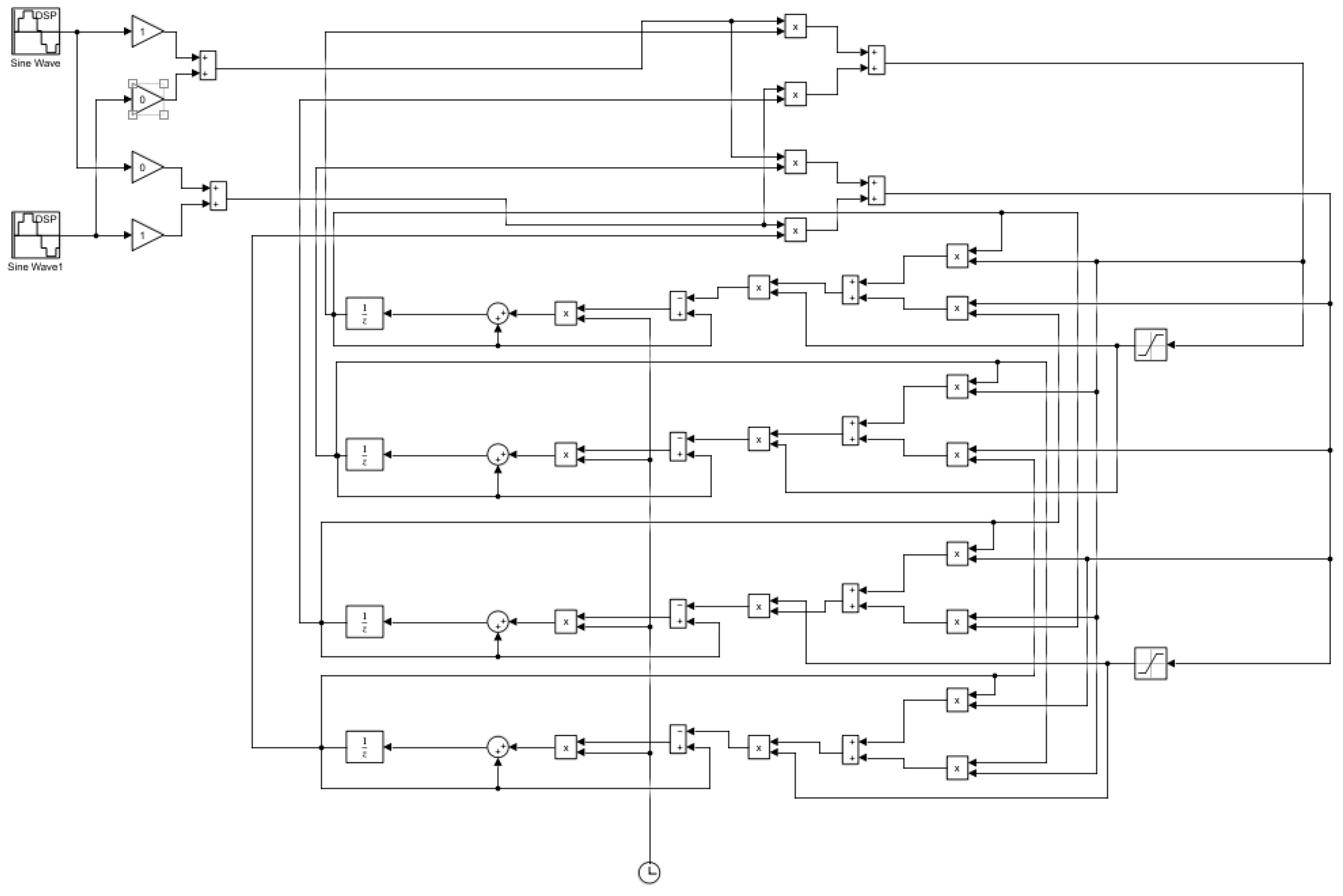
Matlab Simulink’s block of 2 × 2 neural network architecture is seen in Figure 11. To evaluate the effectiveness of the algorithm, sine wave signals were used. Table 1 shows the hardware utilization of the existing structure with the proposed architecture. Due to the time-based multiplexing process, a single MAC architecture is sufficient to carry out any tap values.
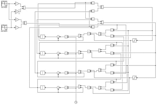
Figure 11.
Block diagram of 2 × 2 neural network.

Table 1.
Comparison of proposed architecture with existing architecture.
In Table 2, the proposed architecture is compared with conventional devices. In the proposed architecture, the 10-tap filter is highly compared with other devices, and the 32-tap filter output is solved since MAC has the taps. The suggested LMS structures dramatically reduce space when compared with the conventional FIR filter structures and boost speed because they use infrastructure for single MAC cores with an ADALINE filter.
Table 2.
Synthesis comparison of the existing system with the proposed architecture.
The results of the synthesis of 10-tap filter architectures are compared in Table 3 with the results of the synthesis of existing architectures using the Xilinx Virtex-5 FPGA device. Comparisons are made between the suggested architectures and the DA-based structure with a carry save adder that Meher presented earlier [21]. Table 4 contains a listing of the minimum sampling period, the maximum sampling frequency, and the number of slices. When compared with the previously used architecture, the speed performance of the proposed time-sharing single MAC ADALINE filter shows an improvement of 70%, and the speed performance of the parallel pipelined multiplier structure shows an improvement of 60%. In comparison with the previously utilized architecture, the slice-delay product demonstrates an improvement of 18%. Pipelined registers placed in between the multiplier and adder structure are utilized in both of the proposed architectures to achieve the highest possible sampling frequency and area efficiency when compared with the architectures that are currently in use. When a single MAC core is utilized, the area required is drastically decreased. Because of the bit product matrix, the pipelined multiplier architecture can maintain a low level of complexity. This is demonstrated in Figure 10, as can be seen. Table 3 presents a comparison of the results of the synthesis performed on the 16-tap and 32-tap proposed adaptive FIR filter with the results performed on the existing architecture by using the FPGA device Altera Stratix EP1S80F1508C6 FPGA. The adaptive FIR filter that used DA architecture and was presented by Daniel Allred [22] made use of an auxiliary LUT with a special address scheme to update the coefficients. The number k represents the total number of LUTs that are utilized in DA-based structures. Due to the single MAC ADALINE core filter structure, the proposed architectures were able to achieve a lower total number of logic elements when compared with the existing architecture. Table 5 and Table 6 present a comparison of the results of the synthesis of the proposed FIR filter with the results of the synthesis of the existing architecture using a variety of Xilinx FPGA devices. Because of the single MAC ADALINE core filter structure, the proposed architectures were able to achieve a significant reduction in the amount of space required while also achieving a greater improvement in speed.
Table 3.
Synthesis comparison of MAC LMS filter with existing architecture.
Table 4.
Synthesis comparison of the existing system with the proposed architecture.
Table 5.
Synthesis comparison of proposed MAC LMS filter with adaptive architectures.
Table 6.
Synthesis results of proposed MAC LMS filter with adaptive filter.
6. Conclusions
This study implements an area-efficient MAC with an adjustable coefficient-based ADALINE filter using the LMS scheme and tests the throughput for 10 taps and 32 taps. The MAC core’s time-division-based multiplier topology promises a considerable reduction in hardware costs. When compared with the corresponding traditional design, the speed of the proposed designs for the ADALINE filter increased by around four times. The proposed 10-tap single MAC ADALINE filter implementation operates at input sampling frequencies of up to 202 MHz, which is 25% faster than the existing implementation and takes up 20% less space. In comparison with traditional designs, the proposed architectures significantly reduce hardware complexity while also improving speed.
Author Contributions
Conceptualization, M.R.E. and J.B.P.; methodology, M.R.E. and J.B.P.; software, M.R.E.; validation, J.B.P.; formal analysis, M.-F.L.; investigation, M.-F.L.; resource, J.B.P.; data curation, M.-F.L.; visualization, J.B.P. and M.-F.L.; supervision, J.B.P.; project administration, M.R.E. All authors have read and agreed to the published version of the manuscript.
Funding
This research has not received any external funding.
Institutional Review Board Statement
Not applicable.
Informed Consent Statement
Not applicable.
Data Availability Statement
Publically available data are analyzed in this study, and those data can be analyzed here: https://in.mathworks.com/help/deeplearning/ug/adaptive-neural-network-filters.html;jsessionid=4799a360fd1b664dfdd247d10815; https://in.mathworks.com/help/dsp/adaptive-filters.html; https://www.xilinx.com/products/silicon-devices/fpga/virtex-ultrascale-plus.html (11 September 2022).
Acknowledgments
The authors also wish to thank the anonymous reviewers for their valuable comments.
Conflicts of Interest
The authors declare no conflict of interest.
References
- Datta, D.; Dutta, H.S. High performance IIR flter implementation on FPGA. J. Electr. Syst. Inf. Technol. 2021, 8, 2. [Google Scholar] [CrossRef]
- Yeary, M.B.; Griswold, N.C. Adaptive IIR filter design for single sensor applications. IEEE Trans. Instrum. Meas. 2002, 51, 259–267. [Google Scholar] [CrossRef]
- Harada, A.; Nishikawa, K.; Engineering, E. A Pipelined Architecture for normalized LMS adaptive digital filter. ICICE Trans. Fundam. Electron. 1999, 82, 73–76. [Google Scholar]
- Rehman, A.U.; Khan, F.; Jadoon, B.K. Analysis of adaptive filter and ICA for noise cancellation from a video frame. In Proceedings of the 2016 International Conference on Intelligent Systems Engineering (ICISE), Islamabad, Pakistan, 15–17 January 2016; pp. 250–255. [Google Scholar] [CrossRef]
- Ting, L.K.; Woods, R.; Cowan, C.F.N. Virtex FPGA implementation of a pipelined adaptive LMS predictor for electronic support measures receivers. IEEE Trans. Very Large Scale Integr. Syst. 2005, 13, 86–94. [Google Scholar] [CrossRef]
- Guerrero-Mosquera, C.; Navia-Vázquez, A. Automatic removal of ocular artefacts using adaptive filtering and independent component analysis for electroencephalogram data. IET Signal Process. 2012, 6, 99–106. [Google Scholar] [CrossRef]
- Pari, B.; Dhandapani, V.; Mariammal, K. An optimized MAC based architecture for adaptive digital filter. Indian J. Eng. Mater. Sci. 2020, 27, 906–915. [Google Scholar]
- Sharma, S.; Kumar, V.; Kumar, R. Supervised Online Adaptive Control of Inverted Pendulum System Using ADALINE Artificial Neural Network with Varying System Parameters and External Disturbance. Int. J. Intell. Syst. Appl. 2012, 4, 53–61. [Google Scholar] [CrossRef]
- Wu, J.M.; Yang, Y.C. Nonlinear independent component analysis by learning generalized adalines. In Proceedings of the IInternational Joint Conference on Neural Networks, Orlando, FL, USA, 12–17 August 2007; pp. 530–535. [Google Scholar] [CrossRef]
- Singh, P. Hardware Implementation of MAC using MATLAB Simulink and FPGA. GRD J. Glob. Res. Dev. J. Eng. 2017, 2, 38–44. [Google Scholar]
- Britto Pari, J.; SP, J.V.R. Anoptimized Architecture For Adaptive Digital Filter. ARPN J. Eng. Appl. Sci. 2015, 10, 4964–4970. [Google Scholar]
- Fah, L.B.; Hussain, A.; Samad, S.A. Speech enhancement by noise cancellation using neural network. In Proceedings of the 2000 TENCON Proceedings. Intelligent Systems and Technologies for the New Millennium (Cat. No.00CH37119), Kuala Lumpur, Malaysia, 24–27 September 2000; pp. 39–42. [Google Scholar] [CrossRef]
- Zhang, W. System identification based on an improved generalized ADALINE neural network. In Proceedings of the2011 Chinese Control and Decision Conference (CCDC), Mianyang, China, 23–25 May 2011; pp. 789–794. [Google Scholar] [CrossRef]
- Signal, N. Implementation of Block Least Mean Square Adaptive Algorithm for Effective Noise Cancellation in Speech Signal. Int. J. Electr. Electron. Eng. Res. 2011, 1, 1–11. Available online: http://www.tjprc.org/files/tjprcfile15.pdf (accessed on 11 September 2022).
- Singh, V.; Somani, V.; Manikandan, J. FPGA implementation of blind source separation using a novel ICA algorithm. In Proceedings of the 2017 IEEE International Conference on Consumer Electronics-Asia (ICCE-Asia), Bengaluru, India, 5–7 October 2017; pp. 67–71. [Google Scholar] [CrossRef]
- Rekha, K.; Nagabushan, B. FPGA Implementation of NLMS Algorithm for Receiver in wireless communication system. Ijcsns 2010, 10, 72–86. Available online: http://paper.ijcsns.org/07_book/201012/20101212.pdf (accessed on 18 November 2022).
- Tornez-Xavier, G.M.; Flores-Nava, L.; Gómez-Castañeda, F.; Moreno-Cadenas, J.A. FPGA implementation of the ICA algorithm using multiplexing. In Proceedings of the 2015 12th International Conference on Electrical Engineering, Computing Science and Automatic Control (CCE), Mexico City, Mexico, 28–30 October 2015. [Google Scholar] [CrossRef]
- Ramos, R.; Mànuel-Làzaro, A.; Del Río, J.; Olivar, G. FPGA-based implementation of an adaptive canceller for 50/60-Hz interference in electrocardiography. IEEE Trans. Instrum. Meas. 2007, 56, 2633–2640. [Google Scholar] [CrossRef]
- Woods, R.; Ting, L.; Cowan, C.F.N. High speed FPGA based implementation of delayed LMS filters. J. CLSI Signal Process. Syst. Signal Image Video Technol. 2005, 39, 113–131. [Google Scholar]
- Jindapetch, N.; Chewae, S.; Phukpattaranont, P. FPGA implementations of an ADALINE adaptive filter for power-line noise cancellation in surface electromyography signalsography signals. Meas. J. Int. Meas. Confed. 2012, 45, 405–414. [Google Scholar] [CrossRef]
- Meher, P.K.; Park, S.Y. High-throughput pipelined realization of adaptive FIR filter based on distributed arithmetic. In Proceedings of the 2011 IEEE/IFIP 19th International Conference on VLSI and System-on-Chip, Hong Kong, China, 3–5 October 2011; pp. 428–433. [Google Scholar]
- Allred, D.J.; Yoo, H.; Krishnan, V.; Huang, W.; Anderson, D.V. LMS adaptive filters using distributed arithmetic for highthroughput. IEEE Trans. Circuits Syst. I Reg. Pap. 2005, 52, 1327–1337. [Google Scholar] [CrossRef]
- Rosado-Muñoz, A.; Bataller-Mompeán, M.; Soria-Olivas, E.; Scarante, C.; Juan, F. Guer rero-MartínezFPGA implementation of an adaptive filter robust to impulsive noise: Two approaches. IEEE Trans. Ind. Electron. 2011, 58, 860–870. [Google Scholar] [CrossRef]
- Parmar, C.A.; Ramanadham, B.; Darji, D. FPGA Implementation of hardware efficient adaptive filter robust to impulsive noise. IET Comput. Digit. Technol. 2017, 11, 107–116. [Google Scholar] [CrossRef]


Disclaimer/Publisher’s Note: The statements, opinions and data contained in all publications are solely those of the individual author(s) and contributor(s) and not of MDPI and/or the editor(s). MDPI and/or the editor(s) disclaim responsibility for any injury to people or property resulting from any ideas, methods, instructions or products referred to in the content. |
© 2023 by the authors. Licensee MDPI, Basel, Switzerland. This article is an open access article distributed under the terms and conditions of the Creative Commons Attribution (CC BY) license (https://creativecommons.org/licenses/by/4.0/).