1. Introduction
Sixth generation (6G) mobile wireless communication, as an upcoming communication standard, will take up more data-intensive applications in the future. Recently, fifth generation (5G) mobile wireless communication has been gradually commercialized, but the requirement for 6G not only provides better communication quality but also higher data transmission rates. With potential application requirements and a great demand for 6G mobile wireless communication, future wireless networks face dramatically crucial challenges as well as opportunities.
An important application of 6G wireless communication technology is intelligent transportation. While cellular V2X (C-V2X) wireless technology offers the possibility of safe driving, 6G wireless communications have set autonomous driving as an application goal, aiming to achieve a more convenient internet of vehicles (IoVs) architecture [
1,
2]. In addition, 6G wireless communications will be able to provide more accurate traffic assistance management information and more secure data transmission solutions for vehicles. Therefore, 6G wireless communications will establish a fully intelligent and fully automated IoVs architecture [
3,
4].
On the other hand, cybertwin technology is expected to act as a data analysis center for vehicles at the edge of the network and collects a large amount of data from the vehicle network through uninterrupted communication with vehicles [
5,
6], which includes a vehicle’s mobility, C-V2X communication resource availability, load on the IoV network, wireless line-of-sight (LoS) blockage, fading intensities, Doppler shift data, network anomalies detected, etc. [
7,
8]. Specifically, cybertwin can reasonably allocate communication channel resources, such as information transmission power, data transmission rate, and channel resource allocation, through the relevant information collected from vehicles, which is collated and intelligently analyzed. Moreover, cybertwin can intelligently select the most encryption keys according to the current security level of the vehicle network to improve network security [
9]. In particular, cybertwin is able to estimate vehicle density based on deep learning and optimization algorithms [
10], and efficiently manage vehicle traffic flow to improve the intelligent services of the telematics network. Therefore, cybertwin can better help mobile users record usage data and decide on data usage through data learning. However, the exchange of information between users and cybertwin devices requires reliable and low-latency communication links. To solve this issue, 6G-enabled IoV architecture is designed to further avoid road risks through a 3-D display of road safety and the environment. To achieve this goal, 6G vehicles will be equipped with communication systems supporting higher resolution and information accuracy to enhance security. In addition, 6G wireless communication systems have the potential to enable highly intelligent urban traffic management. By sharing large amounts of accurate and reliable road vehicle traffic information, data can be intelligently analyzed to reduce road conditions such as traffic jams.
In order to implement the architecture guided by 6G, extremely high data rates and low data latency are required [
11]. However, due to the dynamic connectivity and high mobility of IoVs, communication links between vehicles and surroundings become unreliable. Because of the randomness of traditional wireless communications, the propagation was once regarded as an uncontrollable behavior entity between transmitter and receiver. Due to the uncontrollable interaction between transmitted radio waves and surrounding objects, the channels experience severe fading as well as pass loss, leading to significant performance loss at the receiver.
In the cybertwin-driven 6G vehicular network [
12], the authors primarily considered vehicle blockage scenarios in urban areas with dense building layouts and traffic intersections, making the information transmission conditions poor and less reliable, while vehicle mobility is accompanied by the Doppler effect. As the Doppler shift is proportional to the operating frequency and relative speed of the transmitter and receiver, it will result in the rapid fluctuation of the power amplitude of the received signal.
To overcome the problems of unreliable wireless channels, high Doppler shift, and LoS link reduction, intelligent meta surfaces with real-time reconfigurable characteristics (named reconfigurable intelligent surfaces (RISs) [
13], which adapt transmissions to the propagation environment with smart-controlled software, effectively improving channel quality) have recently attracted considerable attention in the field of mobile communications. Specifically, the time-varying, passive, reflective elements on the surface of an RIS can eliminate the fast fluctuations generated by the Doppler effect and ensure the stability of the received signal size [
14], enhancing vehicle positioning capability and data security. By means of current research, the RIS has been introduced into emerging wireless networks [
15,
16] as an architecture to enable effective energy and spectrum, high coverage, and low cost, being composed of a large number of inexpensive, passive reflecting elements controlled by a preprogrammed controller [
17]. By properly adjusting the phase shift of the reflective elements, it can not only enhance desired signals and suppress undesired signals, but also effectively improve radio transmission performance as well as make the local channel-state information (CSI) controllable [
15,
18].
Clearly, in future IoV systems, the RIS will serve as a primary communication medium between users and the network. In an outdoor environment, RISs can be deployed on fixed or non-fixed objects such as buildings, street lights, and vehicles to assist wireless communication systems. Meanwhile in an indoor environment, RISs can be deployed on walls or ceilings to increase mobile broadband rates and assist large-scale artificial intelligence (AI)-type applications. Compared with 5G wireless communications, i.e., massive, multiple-input, multiple-output (MIMO) technology, RISs simultaneously reduce the energy loss and hardware cost of the network since they do not require an RF chain in hardware. It is even possible to reduce the number of corresponding antennas in the base station (BS) and achieve almost the same performance as the massive MIMO technology via the passive beamforming of RIS [
19].
In current applications, communication between transmitters and receivers can be effectively assisted by RISs. For instance, when a user is located in a poor-quality environment, the communication can be assisted by reflecting signals to the desired location through RISs deployed in the surrounding area. In general, an RIS can expand network coverage, effectively reduce the probability of interruptions, and improve the quality of service (QoS) for users. In addition, the deployment of RISs can also improve the communication coverage and communication interference problems for cell edge users. A large amount of research on reflection coefficient optimization, antenna module assignment, and channel quality estimation is being conducted in RIS-assisted IoV systems.
On the other hand, NOMA is envisioned as a promising technique to improve the spectrum as well as energy efficiency [
20]. NOMA has the advantage of accommodating more users on the same resource block, which includes frequency and time, utilizing superimposition coding at the transmitter and successive interference cancellation (SIC) at the receiver, which can reduce interference from users with better channel quality to users with weaker channel quality, thus improving user fairness and reducing the probability of channel-blocking for IoV networks. Based on the diverse channel conditions required for NOMA, random channels can be intelligently controlled using RISs; the integration of these has been explored in recent studies [
21,
22,
23,
24]. In [
21], the authors proposed a user-pairing NOMA system, where passive beamforming weights are designed by RISs to obtain significant improvements in the power domain. In [
22], a simple transmission design for an RIS-assisted NOMA downlink is proposed, in which a traditional spatial division multiple access (SDMA) is used to generate orthogonal beams. Particularly, the authors in [
23] investigate a RIS–NOMA downlink, where the elements number (in this work, we use “elements number” to indicate the number of elements in the RIS) of the RIS, power allocation, and other factors are illustrated to play important roles in improving system performance. However, most of these works do not consider the influence of RIS elements on sum-rate in detail under the NOMA principle. In addition, the authors in [
24] derive the tight upper bound of the achievable capacity when an RIS serves for a single user under NOMA technology, without considering the varying of sum-rate for multiple users.
From the above discussions, it can be seen that the integration of NOMA and RISs can significantly improve performance gain, while the balance point of ergodic sum-rate and different channel qualities deserve further investigation. Therefore, in this paper, the sum-rate of a RIS–NOMA IoV network is studied, and the main contributions are summarized as follows.
We propose a RIS–NOMA IoV network consisting of two near and far users, where the RIS is divided into two sectors serving different users. The reflecting elements number of the RISs that serve different users is investigated, where the equivalent capacity over diverse channel conditions is studied to elaborate the effect on element allocations.
The trade-off between the reflecting elements number of the RIS and channel path loss is also investigated, where the fixed locations for near and far user are considered, respectively.
Numerical results verify the accuracy of our analysis as well as the effectiveness of the proposed scheme, providing significant improvements in terms of achievable capacity.
2. System Model and Proposed Scheme
In IoV networks, the Doppler effect generated by the high mobility of vehicles affects the quality of transmitted signals. The authors in [
14] showed that the real-time adjustability of an RIS can effectively improve the problem of rapid fluctuations in received signal strength caused by the Doppler effect, and further demonstrated that the strength of the Doppler effect gradually decreases with the number of RISs deployed, thereby completely eliminating the multi-path effect; even the deployment of a small number of RISa in urban traffic scenarios can significantly reduce the Doppler propagation of received signals. The authors in [
25] showed that, for vehicles traveling at 90 mph, deploying only 16 elements of RISs at the cell edge is sufficient to obtain substantial power-efficiency gains and mitigate a Doppler-induced error floor using the proposed channel estimation technique. In dense traffic scenarios, a large number of RIS elements can be divided into multiple blocks to serve different users and mitigate the Doppler effect on the received signal using the channel estimation technique proposed in [
25]. In addition, this paper also considered more ideal IoV networks; we will consider more complex traffic scenarios in future studies.
Considering that LoS fading and channel gains are inversely proportional to distance, our proposed RIS–NOMA IoV network is shown in
Figure 1, which consists of one source (S), one RIS, and two users (A and B), and assumes all nodes are equipped with one antenna. In the direct channels from S to the RIS, users A and B are denoted as
, for
, and the reflecting channels from the RIS are denoted as
, for
, where the channel gain of
is considered greater than
, due to the fact that A experiences a farther distance than B. The reflecting channel gain for the cascaded link can not be obtained directly, since the improved channel gain using an RIS depends on the elements number
N [
5], where the sum of direct as well as reflecting channel gain
of A has the ability to perform better than
of B,
representing the norm of the vector. However, the NOMA technique requires us to allocate the power distribution coefficients with different channel gains to ensure user fairness, while an RIS can change channel gains by adjusting the appropriate elements number. Therefore, channel estimation as well as power allocation become crucial issues to be considered in RIS–NOMA IoV networks.
Letting
for
as the power allocation factor with
, the transmit signal at S can be expressed as
, where
and
are the desired signals for A and B, respectively. According to the NOMA allocation principle, the far user will be allocated higher transmission power to ensure the quality of service, and the near user will be allocated lower transmission power. In our proposed system, two power allocation methods are investigated with different elements numbers of the RIS, which are given as
For simplicity, we assume that the power allocation factor is greater than in the following section, since the assumption of is similar to that of and thus can be omitted due to the limitation of space.
Considering an RIS equipped with fixed
N elements, we divide the elements of the RIS into two sectors to serve different users, where
elements serve user B and
elements serve user A. According to the new element allocation of the RIS, the channel gains from S to the RIS and the RIS to A are denoted as
,
, and
,
is used to denote channel gains from S to the RIS and the RIS to B. In addition, we assume that all channels experience Rayleigh fading distribution, and the received signals at A and B can be respectively expressed as
where
P represents the transmission power at S,
and
are the data symbols with
,
represents the phase shift matrix of the RIS to serve A,
represents lossless reflection,
represents the phase shift caused by the
i-th element for
,
represents the phase shift matrix of the RIS to serve B,
means the phase shift reflected by the
j-th element for
, and the additive white Gaussian noise (AWGN) at A and B is with zero mean and variance
.
In our proposed system, user A decodes
by treating
as interference, since
is the undesired symbol at A. According to the NOMA decoding principle,
can be decoded at B after the successful decoding of
by means of SIC, since user B only requires symbol
with a low power. Therefore, the SNRs for users A and B can be respectively given as
and
Thus, the sum-rate of users B and A can be expressed as
where
is the expectation value of
x.
3. Peformance Analysis
In this section, since an RIS can improve the channel quality of different users by intelligently allocating a large number of reflecting elements, the appropriate number to ensure the equivalent ergodic sum-rate for the proposed system has been investigated, where different channel conditions for users A and B are considered. In conventional NOMA systems, larger power allocation coefficients can be allocated to the user with poor channel quality, aiming to ensure the user fairness. However, the channel gains will be flexibly changed by the reflecting elements of the RIS, where the channel comparison deserves further evaluation. For a simple assumption, two power allocation schemes can be investigated to address this difficult problem.
- (1)
Power coefficient:
Following the NOMA principle, the power distribution coefficient allocated to a poor channel is larger, with
. Considering
, user B is closer to the transmission source, and thus the channel gain can be assumed as
and
. In addition, according to Equations (4) and (6), it can be further calculated that
; therefore,
, and Equation (
7) can be expressed as
- (2)
Power coefficient:
Considering
, it can be assumed that user A is closer to the transmission source, and thus the channel gain can be expressed as
and
. So, from Equations (4)–(6), we can obtain
,
,
. Similarly, it can be further deduced that
and
, and Equation (
7) can be rewritten as
Since the functions
and
are both monotonically increasing functions, we can similarly obtain that the function in Equation (
6) is also monotonically increasing. Therefore, the phase shift to obtain the maximum rate is
, which means that every term has the same phase as
[
13]. Therefore, we have
Define
following the Rayleigh fading with
, where
s denotes the path loss. In contrast, for a large number of reflecting elements,
follows a non-central chi-square distribution [
24]; thus
. Since
is concave, Jensen’s inequality is used to provide the upper bound on its expected value as:
where
K denotes
. Similarly, we can obtain
where
M denotes
. Therefore, the upper bound of ergodic capacity can be obtained as
To perform the maximum beamforming design, phase shifts are assumed as optimal, and the reflection amplitude is set as
=1. Thus, we can obtain
and
. In the case that CSIs of all channels are completely known, if Equation (
8) is equivalent to Equation (
9), we can express this as
which is equivalent to
It is assumed that each RIS element is of the same size, resulting in all elements in
,
, and
having the same amplitude. For a simple analysis, the average channel gains are given as
,
,
, and
, where
and
. Combing the direct as well as the reflecting channel [
26], the channel gain can be given as
where
and
represent the sum channel gain of users A and B, respectively. Clearly, when the RIS is composed of a small number of a reflecting elements, the achievable capacity provided by the additional cascaded channel of the RIS can be smaller than the direct channel. However, with an increase in the reflecting elements number, the achievable capacity provided by the RIS is significantly improved and has the ability to perform better than the direct channel. Then, we can rewrite Equation (
16) in a more compact form as
After simplifying the equation with mathematical transformations, we have
Moreover, after full expansion, the complete expression can be presented as
Clearly, since this equation is complex and hard to calculate, the number of reflecting elements to obtain the equivalent sum-rate where users experience different channel conditions can be further investigated in a simple approximation. Letting
as the transmit SNR, Equation (
18) can be further rewritten as
where the proposed system is considered to experience the condition of a large SNR, as
, and the approximation of 1 +
can be utilized. Thus, Equation (
20) can be simplified as
Since the restricted power distribution coefficient is
and
, we have
Furthermore, substituting Equation (
17) into Equation (
23), the expression can be given as
where the closed-form expression of the reflecting elements number
can be finally obtained from
Therefore, the number of elements allocated to serve users A and B are respectively obtained, which equalizes the ergodic sum-rate over different channel qualities.
4. Numerical Results
In this section, we evaluate the performance of the proposed system through numerical results. Assuming that all channels follow Rayleigh fading, the path-loss index is set at 2.2. For simplicity, the position of each node is set as , , , and .
Figure 2 shows the achievable capacity versus the number of reflecting elements allocated for user B. In our proposed system, the transmission power is set as
P = −30 dBm, and the number of elements is fixed at 5000. Clearly, a greater number of reflective elements of an RIS assigned to a user leads to better channel quality. In this paper, the simulation assumes that the initial state has not assigned RIS elements to user B, resulting in poor channel quality, and hence user B has a lower capacity. With an increase in the number of reflecting elements allocated to user B, the channel quality improves, and the corresponding data rate gradually increases. As the number of reflective antennas assigned to user A by the RIS decreases, the achievable capacity at A gradually decreases, while the achievable capacity for B increases first and then decreases. There is a rate intersection between A and B, where represented transmission rates for the two channels are equal. Then, with an increase in the number allocated for B, the achievable capacity of B increases to the peak value first and then decreases. The increased number of reflective elements allocated to user B by the RIS improves the channel quality, and according to the principle of transmitted power allocation by NOMA, more transmitted power will be allocated to the user with poorer channel quality. In this manner, the sum-rate will appear to rise and then fall. Moreover, according to Equation (
7), it can be deduced that this peak point is the maximum value of the sum-rate. According to the calculation of Equation (
25), the elements number of this point can be calculated as 2570.
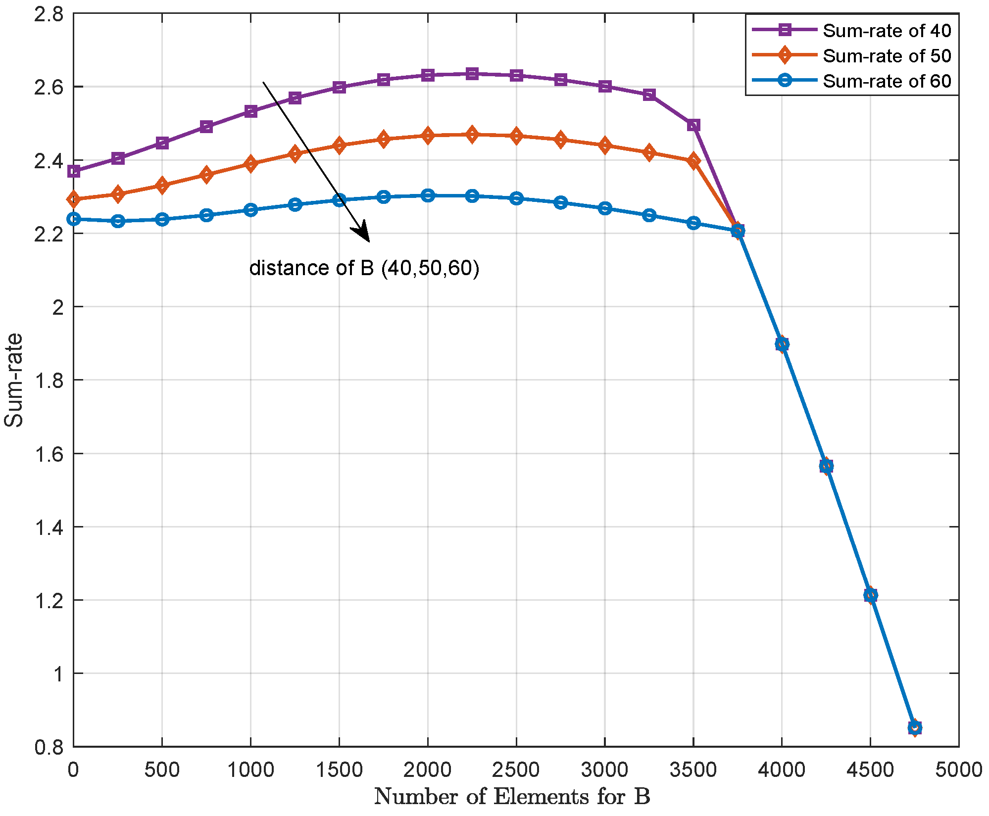
Figure 3 shows that the achievable capacity performs differently when user B experiences diverse channel conditions and user A is fixed. Assuming the distances from user S to B are 40, 50, and 60 m, it can be seen that the sum-rate first rises to a peak value and then drops rapidly with an increase in the number of RIS-allocated elements. The number of reflecting elements needed to obtain the equivalent transmission sum-rate gradually increases when the distance from user B to the source increases. Clearly, the rapid decrease in sum-rate after reaching the peak value is due to the minimum value for the SINR being changed by means of our proposed scheme, which is given as Equations (7) and (9). For example, when
, as the elements number to service user B, increases, the channel quality of B is gradually better than A, and thus the minimum value in Equation (
9) can be taken as
, where the number of elements to service user B increases and the sum-rate decreases rapidly.
Figure 4 shows that the achievable capacity of the system performs differently when user B is fixed and user A is mobile. As the distances from S to A are set as 60, 70, and 80 m, the sum-rate of our proposed system first rises rapidly to a peak value and then gradually decreases with the increase in the number of RIS-allocated elements. In addition, when the distance from user A to the transmission source gradually increases, the number of elements needed to obtain the equivalent ergodic sum-rate gradually decreases. Similarly, the ergodic sum-rate dramatically degrades after reaching a peak value because the minimum value of the SINR is changed in our proposed schemes, as shown in Equations (7) and (9). When
, with the elements number allocated to serve user B being small, the channel quality of A is better than that of B. However, according to the power allocation principle of NOMA, more transmitted power will be allocated to user B with poorer channel quality; with an increasing elements number to serve user B, its channel quality becomes better than that of user A, and the minimum value of the SINR in Equation (
8) varies from
to
, leading to a decrease in the sum-rate after reaching the peak value.
Figure 5 shows the variety of the ergodic rate when the transmission power of the signal source increases. As the transmission power is fixed at −15 dBm, the intersection where user A and user B will obtain equal performance occurs at a large elements number, which reveals that more elements need to be allocated to users in order to achieve the same sum-rate. However, when the transmission power is 1 dBm, user A and user B do not have an intersection with the same rate or the same sum-rate. It can be observed that when the transmitting power is small, an elements number exists to obtain the equivalent ergodic sum-rate under different channel conditions. However, when the transmission power for the signal source increases, that is, the SNR gradually increases, the elements number to obtain an equal ergodic rate for users A and B improves. Therefore, the elements number needed to achieve the equivalent sum-rate under different channel qualities only exists with a small SNR. Conversely, when the SNR is large, there is no elements number that will obtain an equal sum-rate under different channel conditions.
Figure 6 shows the relationship between the number of users served by an RIS and the sum-rate. In the previous NOMA–RIS scheme, all intelligent reflector antennas serve a single user. Our proposed scheme intelligently divides the elements of the RIS into two parts to serve different users separately and considers the feasibility of the scheme from the perspective of sum-rate. From simulation results, it can be seen that under the same NOMA conditions, the RIS intelligently distributes the reflector antennas to serve two users and has a better sum-rate performance than that of the one serving a single user. Clearly, dividing an RIS into multiple blocks to serve different users, applied to traffic-dense, multi-user IoV scenarios, will significantly improve system performance.


