


Phase-Noise Characterization in Stable Optical Frequency Transfer over Free Space and Fiber Link Testbeds †
 , , , , , , , , and
Abstract
:1. Introduction
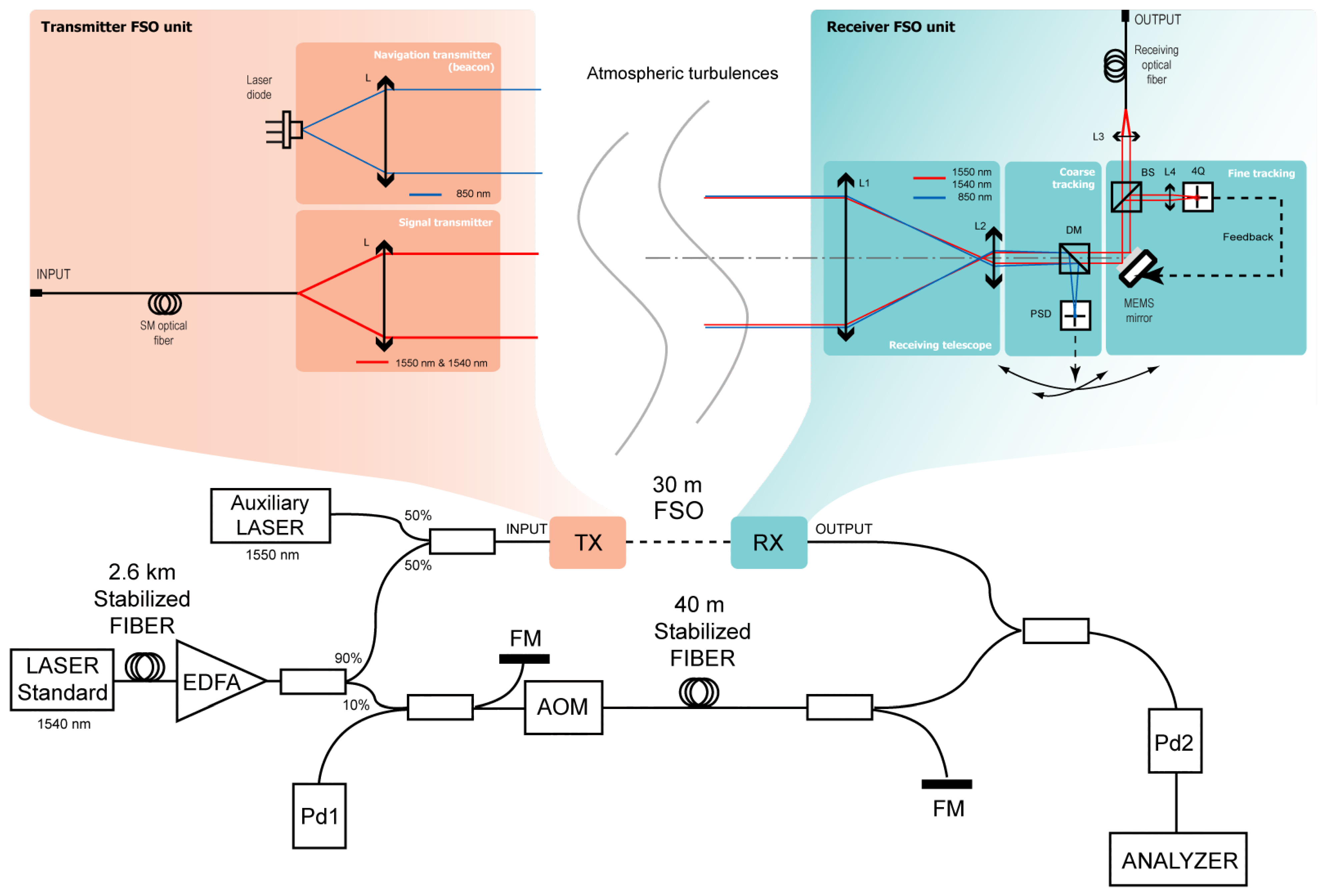
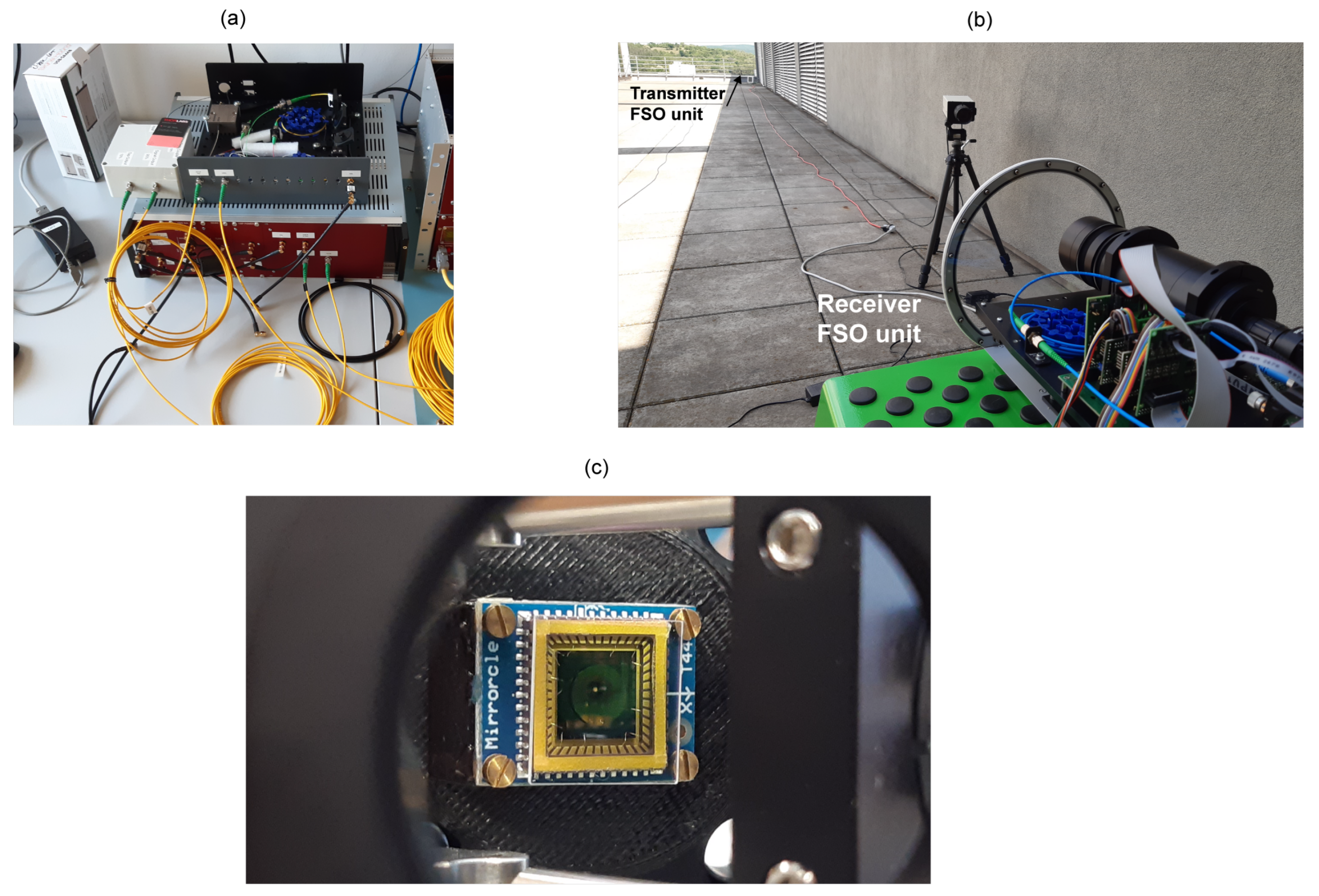
2. The Experiment
3. Results and Discussion
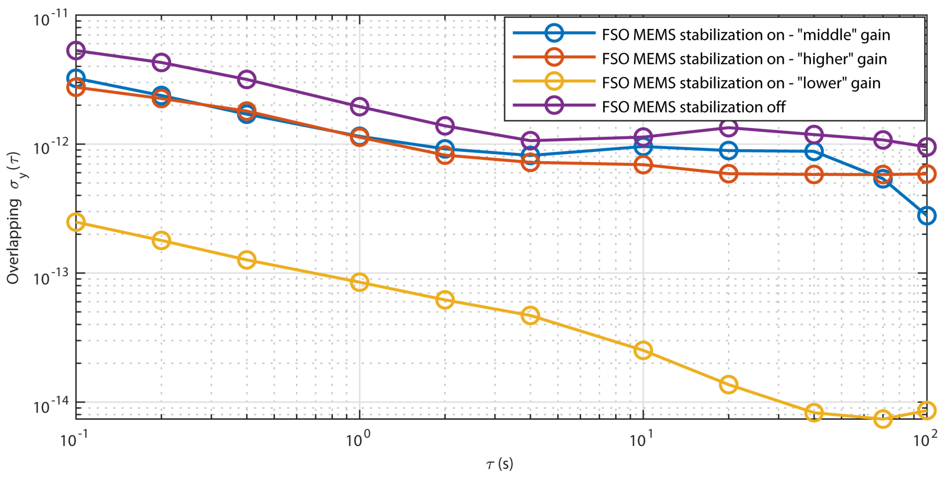
3.1. Laser Beam Stabilization Performance
3.2. Analysis of the RF Beat-Note Signal
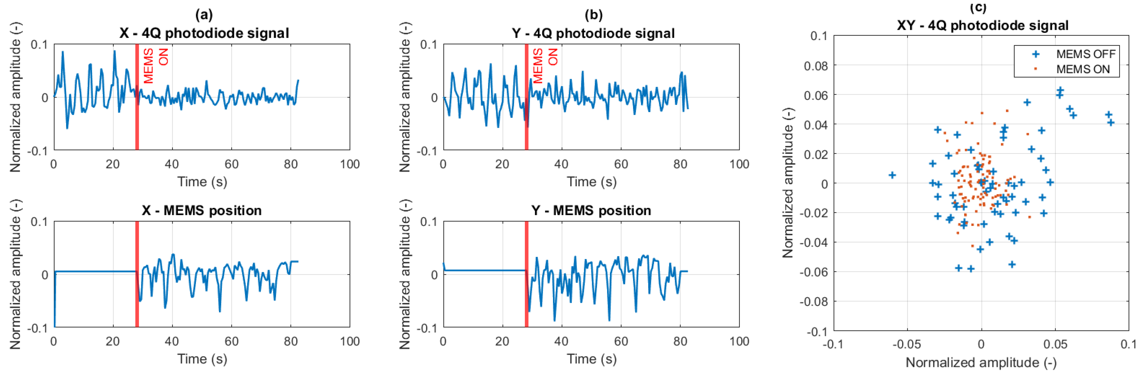
3.2.1. Time-Domain Analysis
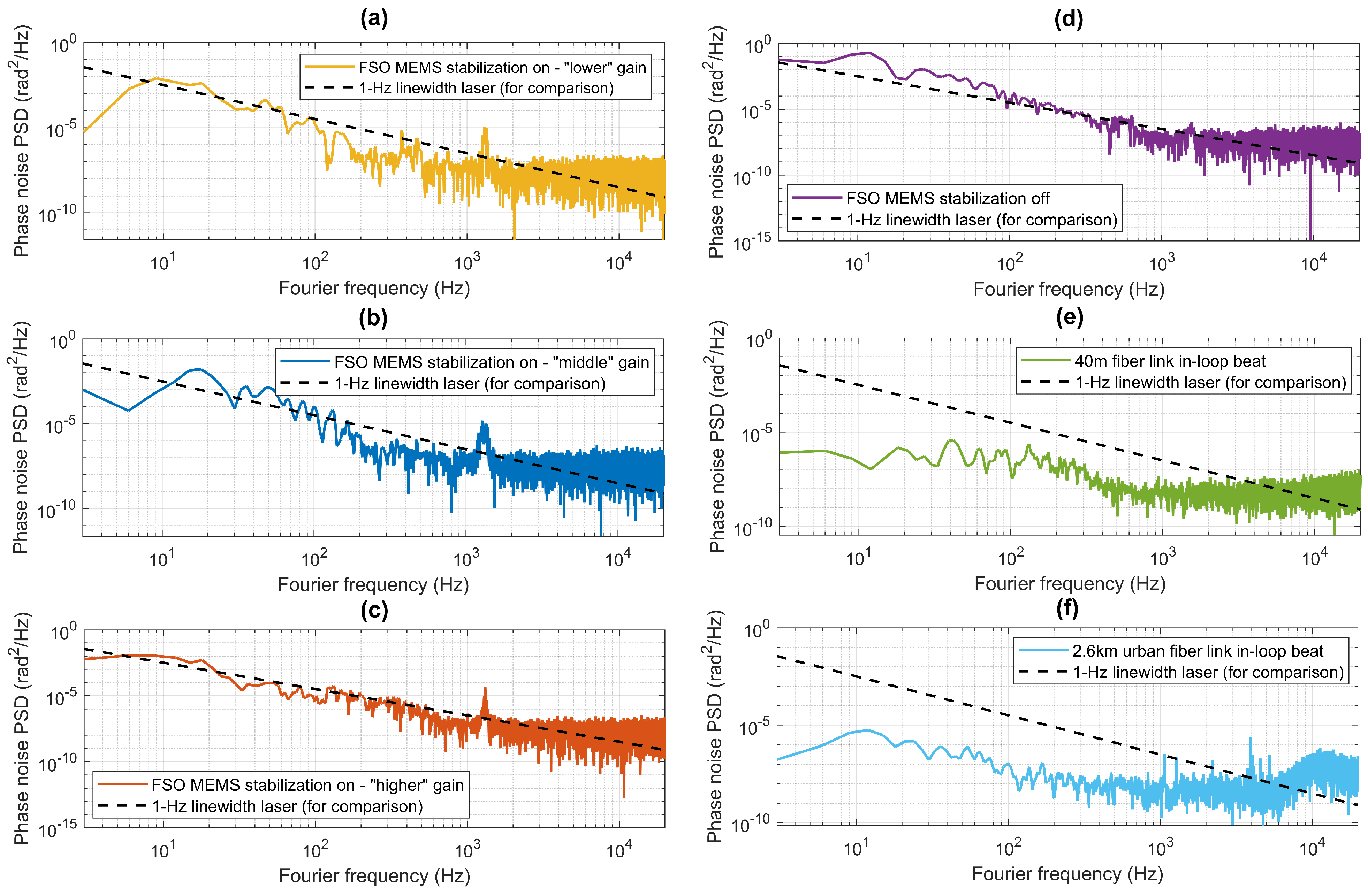
3.2.2. Frequency-Domain Analysis
4. Conclusions
Author Contributions
Funding
Data Availability Statement
Conflicts of Interest
Abbreviations
| MEMS | Micro Electronic Mechanical Systems |
| DWDM | Dense Wavelength-Division Multiplexing |
| HCF | Hollow Core Fiber |
| SMF | Single-Mode Fiber |
| FSO | Free-Space Optics |
| ISS | International Space Station |
| OAC | Optical Atomic Clock |
| AOM | Acousto-Optic Modulator |
| FM | Faraday Mirror |
| RF | Radio Frequency |
| EDFA | Erbium Dopped Fiber Amplifier |
| Pd | Photodetector |
| TX | Transmitter |
| RX | Receiver |
| PSD | Position-Sensitive Device |
| BS | Beam Splitter |
| DM | Dichroic Mirror |
| 4Q | Four-Quadrant Photodetector |
References
- Ovchinnikov, Y.; Chalupczak, W.; Szymaniec, K.; Marra, G. Towards a high-stability Rb fountain frequency standard. In Proceedings of the 20th European Frequency and Time Forum, Braunschweig, Germany, 27–30 March 2006; pp. 186–188. [Google Scholar]
- Bernier, L. Predictability of a Hydrogen Maser Time Scale. In Proceedings of the European Frequency and Time Forum, Besançon, France, 21–24 March 2005; pp. 438–441. [Google Scholar]
- Meekhof, D.M.; Jefferts, S.R.; Stepanovíc, M.; Parker, T.E. Accuracy Evaluation of a Cesium Fountain Primary Frequency Standard at NIST. IEEE Trans. Instrum. Meas. 2001, 50, 507–509. [Google Scholar] [CrossRef]
- Leo, P.J.; Julienne, P.S.; Mies, F.H.; Williams, C.J. Collisional Frequency Shifts in 133Cs Fountain Clocks. Phys. Rev. Lett. 2001, 86, 3743–3746. [Google Scholar] [CrossRef]
- Parker, T.E. A Comparison of Cesium Fountain Primary Frequency Standards. In Proceedings of the EFTF, Toulouse, France, 22–25 April 2008; pp. 1–7. [Google Scholar]
- Rosenband, T.; Hume, D.B.; Schmidt, P.O.; Chou, C.W.; Brusch, A.; Lorini, L.; Oskay, W.H.; Drullinger, R.E.; Fortier, T.M.; Stalnaker, J.E. Frequency Ratio of Al+ and Hg+ Single-Ion Optical Clocks; Metrology at the 17th Decimal Place. Science 2008, 319, 1808–1812. [Google Scholar] [CrossRef]
- Gill, P.; Barwood, G.P.; Huang, G.; Klein, H.A.; Blythe, P.J.; Hosaka, K.; Thompson, R.C.; Webster, S.A.; Lea, S.N.; Margolis, H.S. Trapped Ion Optical Frequency Standards. Phys. Scr. 2004, T112, 63–67. [Google Scholar] [CrossRef]
- Ludlow, A.D.; Boyd, M.M.; Ye, J.; Peik, E.; Schmidt, P.O. Optical atomic clocks. Rev. Mod. Phys. 2015, 87, 637–701. [Google Scholar] [CrossRef]
- Gellesch, M.; Jones, J.; Barron, R.; Singh, A.; Sun, Q.; Bongs, K.; Singh, Y. Transportable optical atomic clocks for use in out-of-the-lab environments. Adv. Opt. Technol. 2020, 9, 313–325. [Google Scholar] [CrossRef]
- Takamoto, M.; Ushijima, I.; Ohmae, N.; Yahagi, T.; Kokado, K.; Shinkai, H.; Katori, H. Test of general relativity by a pair of transportable optical lattice clocks. Nat. Photonics 2020, 14, 411–415. [Google Scholar] [CrossRef]
- Stuhler, J.; Abdel Hafiz, M.; Arar, B.; Bawamia, A.; Bergner, K.; Biethahn, M.; Brakhane, S.; Didier, A.; Fortágh, J.; Halder, M.; et al. Opticlock: Transportable and easy-to-operate optical single-ion clock. Meas. Sens. 2021, 18, 100264. [Google Scholar] [CrossRef]
- Schioppo, M.; Kronjager, J.; Silva, A.; Ilieva, R.; Paterson, J.W.; Baynham, C.F.A.; Bowden, W.; Hill, I.R.; Hobson, R.; Vianello, A.; et al. Comparing ultrastable lasers at 7 × 10-17 fractional frequency instability through a 2220 km optical fibre network. Nat. Commun. 2022, 13, 212. [Google Scholar] [CrossRef]
- Marra, G.; Margolis, H.S.; Lea, A.N.; Gill, P. High-stability microwave frequency transfer by propagation of an optical frequency comb over 50 km of optical fiber. Opt. Lett. 2010, 37, 1025. [Google Scholar] [CrossRef]
- Marra, G.; Margolis, H.S.; Richardson, D.J. Dissemination of an optical frequency comb over fiber with 3 × 10-18 fractional accuracy. Opt. Express 2012, 20, 1175–1782. [Google Scholar] [CrossRef]
- Grosche, G.; Terra, K.; Predehl, K.; Holzwarth, R.; Lipphardt, B.; Vogt, F.; Sterr, U.; Schnatz, H. Optical frequency transfer via 146 km fiber link with 10-19 relative accuracy. Opt. Lett. 2009, 34, 2270–2272. [Google Scholar] [CrossRef]
- Hong, F.; Musha, M.; Takamoto, M.; Inaba, H.; Yanagimachi, S.; Takamizawa, A.; Watabe, K.; Ikegami, T.; Imae, M.; Fujii, Y.; et al. Measuring the frequency of s Sr optical lattice clock using a 120 km coherent optical transfer. Opt. Lett. 2009, 34, 5. [Google Scholar] [CrossRef]
- Fujieda, M.; Kumagai, M.; Nagano, S.; Yamaguchi, A.; Hachisu, H.; Ido, T. All-optical link for direct comparison of distant optical clocks. Opt. Express 2011, 19, 16498–16507. [Google Scholar] [CrossRef]
- Vojtech, J.; Slapak, M.; Skoda, P.; Radil, J.; Havlis, O.; Altmann, M.; Munster, P.; Velc, R.; Kundrat, J.; Altmannova, L.; et al. Joint accurate time and stable frequency distribution infrastructure sharing fiber footprint with research network. Opt. Eng. 2017, 56, 027101. [Google Scholar] [CrossRef]
- Vojtěch, J.; Altmannová, L.; Smotlacha, V.; Velc, R.; Vohnout, R.; Schnatz, H.; Liebisch, T.C.; Capone, V.; Chiotis, T.; Roberts, G.; et al. CLONETS-DS—Clock Network Services-Design Study Strategy and innovation for clock services over optical-fibre networks in Europe. In Proceedings of the Conference on Lasers and Electro-Optics, San Jose, CA, USA, 9–14 May 2021; Optica Publishing Group: Washington, DC, USA, 2021; p. JTu3A.30. [Google Scholar]
- Cantin, E.; Lopez, O.; Amy-Klein, A.; Chardonnet, C.; Cantin, E.; Tonnes, M.; Meynadier, F.; Pottie, P.E.; Quintin, N.; Camisard, E.; et al. REFIMEVE+: Optical Frequency Dissemination Over 2 × 1300 km of a Telecom Network. In Proceedings of the 2019 Joint Conference of the IEEE International Frequency Control Symposium and European Frequency and Time Forum (EFTF/IFC), Orlando, FL, USA, 14–18 April 2019; pp. 1–3. [Google Scholar] [CrossRef]
- Feng, Z.; Marra, G.; Zhang, X.; Fokoua, E.R.; Sakr, H.; Hayes, J.R.; Poletti, F.; Richardson, D.J.; Slavík, R. Stable Optical Frequency Comb Distribution Enabled by Hollow-Core Fibers. Laser Photonics Rev. 2022, 16, 2200167. [Google Scholar] [CrossRef]
- Sharma, D.; Tripathi, A.; Kumari, M. FSO systems for next generation networks: A review, techniques and challenges. J. Opt. Commun. 2022. [Google Scholar] [CrossRef]
- Mai, V.V.; Kim, H. Beam Control and Tracking Techniques for High- Altitude Airborne Free-Space Optical Communication Systems. In Proceedings of the 2020 International Topical Meeting on Microwave Photonics, MWP 2020, Virtual Conference, 24–26 November 2020; pp. 5–8. [Google Scholar] [CrossRef]
- Singh, R.; Feng, F.; Hong, Y.; Faulkner, G.; Deshmukh, R.; Vercasson, G.; Bouchet, O.; Petropoulos, P.; O’Brien, D. Design and Characterisation of Terabit/s Capable Compact Localisation and Beam-Steering Terminals for Fiber-Wireless-Fiber Links. J. Light. Technol. 2020, 38, 6817–6826. [Google Scholar] [CrossRef]
- Bergeron, H.; Sinclair, L.C.; Swann, W.C.; Khader, I.; Cossel, K.C.; Cermak, M.; Deschênes, J.D.; Newbury, N.R. Femtosecond time synchronization of optical clocks off of a flying quadcopter. Nat. Commun. 2019, 10, 1819. [Google Scholar] [CrossRef] [PubMed]
- Caldwell, E.D.; Deschenes, J.D.; Ellis, J.; Swann, W.C.; Stuhl, B.K.; Bergeron, H.; Newbury, N.R.; Sinclair, L.C. Quantum-limited optical time transfer for future geosynchronous links. Nature 2023, 618, 721–726. [Google Scholar] [CrossRef]
- Schkolnik, V.; Budker, D.; Fartmann, O.; Flambaum, V.; Hollberg, L.; Kalaydzhyan, T.; Kolkowitz, S.; Krutzik, M.; Ludlow, A.; Newbury, N.; et al. Optical atomic clock aboard an Earth-orbiting space station (OACESS): Enhancing searches for physics beyond the standard model in space. Quantum Sci. Technol. 2022, 8, 014003. [Google Scholar] [CrossRef]
- Shen, Q.; Guan, J.Y.; Zeng, T.; Lu, Q.M.; Huang, L.; Cao, Y.; Chen, J.P.; Tao, T.Q.; Wu, J.C.; Hou, L.; et al. Experimental simulation of time and frequency transfer via an optical satellite–ground link at 10–18 instability. Optica 2021, 8, 471–476. [Google Scholar] [CrossRef]
- Kang, H.J.; Yang, J.; Chun, B.J.; Jang, H.; Kim, B.S.; Kim, Y.J.; Kim, S.W. Free-space transfer of comb-rooted optical frequencies over an 18 km open-air link. Nat. Commun. 2019, 10, 4438. [Google Scholar] [CrossRef] [PubMed]
- Shen, Q.; Guan, J.Y.; Ren, J.G.; Zeng, T.; Hou, L.; Li, M.; Cao, Y.; Han, J.J.; Lian, M.Z.; Chen, Y.W.; et al. Free-space dissemination of time and frequency with 10–19 instability over 113 km. Nature 2022, 610, 661–666. [Google Scholar] [CrossRef] [PubMed]
- Yang, J.; IL Lee, D.; Shin, D.C.; Lee, J.; Kim, B.S.; Kang, H.J.; Kim, Y.J.; Kim, S.W. Frequency comb-to-comb stabilization over a 1.3-km free-space atmospheric optical link. Light. Sci. Appl. 2022, 11, 253. [Google Scholar] [CrossRef] [PubMed]
- Yang, J.; Kang, H.J.; Lee, K.; Lee, J.; Kim, Y.J.; Kim, S.W. Phase-stabilized free-space link for optical frequency transfer. Opt. Commun. 2022, 504, 127481. [Google Scholar] [CrossRef]
- Dix-Matthews, B.P.; Schediwy, S.W.; Gozzard, D.R.; Savalle, E.; Esnault, F.X.; Lévèque, T.; Gravestock, C.; D’Mello, D.; Karpathakis, S.; Tobar, M.; et al. Point-to-point stabilized optical frequency transfer with active optics. Nat. Commun. 2021, 12, 515. [Google Scholar] [CrossRef]
- McSorley, S.; Gozzard, D.R.; Karpathakis, S.F.E.; Dix-Matthews, B.P.; Schediwy, S.W. Stabilized free space optical frequency transfer using digitally enhanced heterodyne interferometry. Opt. Lett. 2023, 48, 3637. [Google Scholar] [CrossRef]
- Hu, L.; Xue, R.; Cao, X.; Liu, J.; Wu, K.; Wu, G.; Chen, J. Free-Space Point-to-Multiplepoint Optical Frequency Transfer With Lens Assisted Integrated Beam Steering. IEEE Trans. Instrum. Meas. 2022, 71, 515. [Google Scholar] [CrossRef]
- Vojtech, J.; Smotlacha, V.; Havlis, O.; Vohnout, R.; Spacek, M.; Novak, T.; Andriantsarazo, E.; Slapak, M.; Altmannova, L.; Velc, R.; et al. National Infrastructure for Dissemination of Precise Time and Ultra-stable Optical Frequency also Aiming to Connect Quantum Sources—CITAF. In Proceedings of the Conference on Quantum Optics and Photon Counting, Prague, Czech Republic, 26–27 April 2023; SPIE: St Bellingham, WA, USA, 2023; Volume 12570. [Google Scholar] [CrossRef]
- Barcik, P.; Hrabina, J.; Cizek, M.; Skryja, P.; Kolka, Z.; Pravdova, L. Stable Optical Frequency Transmission over a Free Space Optical Testbed. In Proceedings of the 2022 International Conference on Broadband Communications for Next Generation Networks and Multimedia Applications (CoBCom), Graz, Austria, 12–14 July 2022; pp. 1–4. [Google Scholar] [CrossRef]


| Measurement Description | Integration Interval (Hz) | Phase Noise (rad) |
|---|---|---|
| Transmission in free space, MEMS stabilization on, “middle” gain, l = 30 m | 1–4000 | 0.41 |
| Transmission in free space, MEMS stabilization on, “higher” gain, l = 30 m | 1–4000 | 0.38 |
| Transmission in free space, MEMS stabilization on, “lower” gain, l = 30 m | 1–4000 | 0.28 |
| Transmission in free space, MEMS stabilization off, l = 30 m | 1–4000 | 1.29 |
| Fiber link in-loop beat (noise floor), l = 40 m | 1–4000 | 0.01 |
| Fiber link in-loop beat (noise floor), l = 2.6 km | 1–4000 | 0.01 |
Disclaimer/Publisher’s Note: The statements, opinions and data contained in all publications are solely those of the individual author(s) and contributor(s) and not of MDPI and/or the editor(s). MDPI and/or the editor(s) disclaim responsibility for any injury to people or property resulting from any ideas, methods, instructions or products referred to in the content. |
© 2023 by the authors. Licensee MDPI, Basel, Switzerland. This article is an open access article distributed under the terms and conditions of the Creative Commons Attribution (CC BY) license (https://creativecommons.org/licenses/by/4.0/).
Share and Cite
Barcik, P.; Hrabina, J.; Cizek, M.; Kolka, Z.; Skryja, P.; Pravdova, L.; Cip, O.; Hudcova, L.; Havlis, O.; Vojtech, J. Phase-Noise Characterization in Stable Optical Frequency Transfer over Free Space and Fiber Link Testbeds. Electronics 2023, 12, 4870. https://doi.org/10.3390/electronics12234870
Barcik P, Hrabina J, Cizek M, Kolka Z, Skryja P, Pravdova L, Cip O, Hudcova L, Havlis O, Vojtech J. Phase-Noise Characterization in Stable Optical Frequency Transfer over Free Space and Fiber Link Testbeds. Electronics. 2023; 12(23):4870. https://doi.org/10.3390/electronics12234870
Chicago/Turabian StyleBarcik, Peter, Jan Hrabina, Martin Cizek, Zdenek Kolka, Petr Skryja, Lenka Pravdova, Ondrej Cip, Lucie Hudcova, Ondrej Havlis, and Josef Vojtech. 2023. "Phase-Noise Characterization in Stable Optical Frequency Transfer over Free Space and Fiber Link Testbeds" Electronics 12, no. 23: 4870. https://doi.org/10.3390/electronics12234870
APA StyleBarcik, P., Hrabina, J., Cizek, M., Kolka, Z., Skryja, P., Pravdova, L., Cip, O., Hudcova, L., Havlis, O., & Vojtech, J. (2023). Phase-Noise Characterization in Stable Optical Frequency Transfer over Free Space and Fiber Link Testbeds. Electronics, 12(23), 4870. https://doi.org/10.3390/electronics12234870