Article

Active STARS-Assisted Rate-Splitting Multiple-Access Networks

1
Key Laboratory of Information and Communication Systems, Ministry of Information Industry, Beijing Information Science and Technology University, Beijing 100101, China
2
Key Laboratory of Modern Measurement and Control Technology, Ministry of Education, Beijing Information Science and Technology University, Beijing 100101, China
3
School of Electronic and Information Engineering, Beihang University, Beijing 100191, China
4
Yellow River Conservancy Technical Institute, Kaifeng 475001, China
5
School of Computing, Engineering and Mathematical Sciences, La Trobe University, Melbourne, VIC 3086, Australia
*
Author to whom correspondence should be addressed.
Electronics 2023, 12(18), 3815; https://doi.org/10.3390/electronics12183815
Submission received: 15 August 2023 / Revised: 31 August 2023 / Accepted: 7 September 2023 / Published: 9 September 2023

Abstract

:
The active simultaneously transmitting/reflecting surface (ASTARS) is considered a promising technique to achieve full spatial coverage and overcome multiplicative fading caused by cascaded paths. This paper investigates the performance of ASTARS-assisted rate-splitting multiple-access networks (ASTARS-RSMA) with multiple transmission users (TUs) and reflection users (RUs). The energy-splitting configurations of ASTARS and the effects of imperfect/perfect successive interference cancellation (SIC) on ASTARS-RSMA networks are considered in the analysis. We derive new exact and asymptotic expressions of the outage probability with imperfect/perfect SIC for TUs and RUs. On this basis, we further calculate the diversity orders of TUs and RUs. Moreover, the system throughput and energy efficiency (EE) of ASTARS-RSMA are evaluated in the delay-limited mode. The simulation results confirm the accuracy of the theoretical expressions and show that (i) the outage probability and system throughput with imperfect/perfect SIC of ASTARS-RSMA exceed that of passive simultaneously transmitting/reflecting surface (PSTARS)-assisted RSMA when the number of elements is not too large; (ii) although ASTARS increases power consumption compared to PSTARS, it can bring further EE improvements to RSMA networks.

1. Introduction

Wireless communication technology has developed rapidly in the past decade. As a result, people have put forward higher quality and more diversified requirements for business services [1,2,3]. Therefore, sixth-generation (6G) communication technologies require more efficient utilization of wireless resources and more flexible network design, which triggers extensive research on the reconfigurable intelligent surface (RIS) [4]. The passive RIS (PRIS) is an artificial surface composed of numerous low-cost components with a reconfigurable electromagnetic response. Based on this hardware architecture, PRIS can reconfigure the amplitude and phase of wireless signals, thereby constructing a smart radio environment [5]. In many wireless communication fields, PRIS has been proven to improve the spectrum efficiency, energy efficiency and physical layer security of the system [6,7,8].
However, the conventional reflection-only PRIS has only half of the service area, which means that the transmitter and receiver must be located on the same side of the PRIS. With the development of metasurface technology, a new type of simultaneously transmitting and reflecting surface (STARS) was proposed, which expands the service scope to full space [9]. The key concept of the passive STARS (PSTARS) is to employ elements that can reflect and transmit signals at the same time [10]. Such elements can usually be realized through three hardware structures, namely patch-array-based, antenna-empowered and metasurface-based models [11]. Based on the hardware structure characteristics of metasurface-type PSTARS, the authors of [12] proposed three corresponding protocols, namely time switching, energy splitting (ES) and mode switching (MS). As a further development, the authors of [13] separately analyzed the benefits of these three protocols in PSTARS-assisted wireless networks. In [14], the authors researched the performance superiority of PSTARS over PRIS in terms of system sum rate and effective service range.
As mentioned above, deploying PRIS/PSTARS has brought many benefits to wireless networks, but they also have an inevitable flaw. Specifically, deploying PRIS/PSTARS causes multiplicative path loss, i.e., the path losses of base station (BS) to PRIS/PSTARS and PRIS/PSTARS to users are multiplied, making them generally greater than the direct link [15,16]. To resist severe multiplicative path loss, active RIS (ARIS) has recently been designed; it introduces power amplifiers into conventional PRIS circuits to enhance the incident signals [17]. Compared with conventional amplify-and-forward relaying, ARIS does not perform signal decoding; thus, it is more flexible and efficient [18]. For fairness reasons, the authors confirmed that the system achievable rate of ARIS is higher than that of PRIS under the same total power-consumption conditions [19]. For secure transmission, the authors of [20] studied the joint optimization problem of the reflection matrix at ARIS and the beamforming at transmitter to maximize the secrecy rate. In [21], the authors provided a comprehensive evaluation of bit error rate and energy efficiency (EE) for ARIS-based wireless networks. Inspired by ARIS, the authors of [22] integrated reflection-type amplifiers into a quadrature hybrid to eliminate multiplicative fading loss and achieve full spatial coverage. In [23], the superiority of active STARS (ASTARS) over ARIS in terms of system achievable rate and energy consumption was analyzed in detail. In addition, the author of [24] designed the configuration matrix of ASTARS and the beamforming vector of the access point to maximize the system secrecy rate.
The shortage of spectral resources caused by the growing number of connected devices and user density is also a challenge for 6G technologies [25]. Given that multiple-access (MA) techniques can efficiently utilize available wireless resources to support multiple user communications, such as rate-splitting MA (RSMA), space-division MA (SDMA) and non-orthogonal MA (NOMA), they have led to extensive discussion [26,27,28]. In RSMA, messages are divided at the BS into two parts: the common messages of all users and the private messages of specific users. Upon receiving the superimposed signals, each user utilizes successive interference cancellation (SIC) to decode common messages and private messages, respectively [29]. Based on this flexible interference management capability, RSMA has been shown to outperform NOMA and SDMA in terms of system throughput [30,31]. By adjusting the content and power of common and private messages, RSMA can be transformed into SDMA or NOMA, which is recognized as a trade-off between NOMA and SDMA [32].

1.1. Previous Works

(1) Studies on PRIS/PSTARS-RSMA Networks: Obviously, integrating PRIS/PSTARS into the RSMA network can dynamically configure the radio channels and effectively improve spectral efficiency [33,34,35,36,37,38]. By employing the on–off control protocol, the authors of [33] evaluated the outage performance of edge users and center users in a PRIS-RSMA network. Considering the presence of potential eavesdroppers, the authors in [34] investigated an alternating optimization algorithm to maximize the secrecy rate for legitimate users. In [35], the authors derived theoretical and asymptotic outage probability expressions for PRIS-RSMA networks with discrete phase-shift and random phase-shift strategies. Considering a PRIS-assisted uplink RSMA network, the authors investigated the system throughput based on a block coordinate descent algorithm [36]. Under the spatially correlated Rician fading channels, the authors of [37] derived outage-probability and channel-capacity expressions for PSTARS-RSMA networks with ES and MS modes. A coupled phase-shifted PSTARS-assisted uplink communication network was discussed in [38], where RSMA outperforms NOMA in terms of system throughput and user fairness.
(2) Studies on ARIS-RSMA Networks: As a brand-new topic, only a few studies have been researched ARIS-RSMA networks. Recently, an ARIS-RSMA strategy for millimeter-wave hybrid antenna arrays was proposed in [39], where the EE and achievable rate of the strategy with ARIS outperform the conventional PRIS. In [40], the authors integrated ARIS and RSMA into a cellular network to research a plausible trade-off between EE, spectral efficiency and resource efficiency.

1.2. Motivation and Contributions

As mentioned above, to achieve intelligent and high-performance networks, the research on integrating RIS into RSMA networks has gone through a development process from PRIS-RSMA [33,34,35,36] to PSTARS-RSMA [37,38], and further to ARIS-RSMA [39,40]. However, while the reflection-only ARIS-RSMA is able to overcome the multiplicative path loss, it still suffers from the problem of half-space coverage. To the best of our knowledge, the ASTARS-assisted downlink RSMA networks have not been investigated yet. In particular, the effect of ASTARS’s element number, amplification factors and reflection/transmission coefficients on the performance of RSMA networks is still unclear. Moreover, the previous works have considered perfect SIC [33,34,35,36,37,38,39,40], which is difficult to achieve in practical applications. Thus evaluating the performance of ASTARS-RSMA in imperfect SIC scenarios is very critical. Motivated by these reasons, we integrate an ASTARS to assist downlink RSMA network to achieve full spatial coverage and conquer the multiplicative fading, where the imperfect/perfect SIC scenarios are considered. Conditioned on cascaded Rician fading channels, we analyze the outage probability, system throughput and EE for the m-th reflection/transmission users, i.e., R U m and T U m . In accordance with the aforementioned explanations, the primary contributions of this paper are summarized as follows:
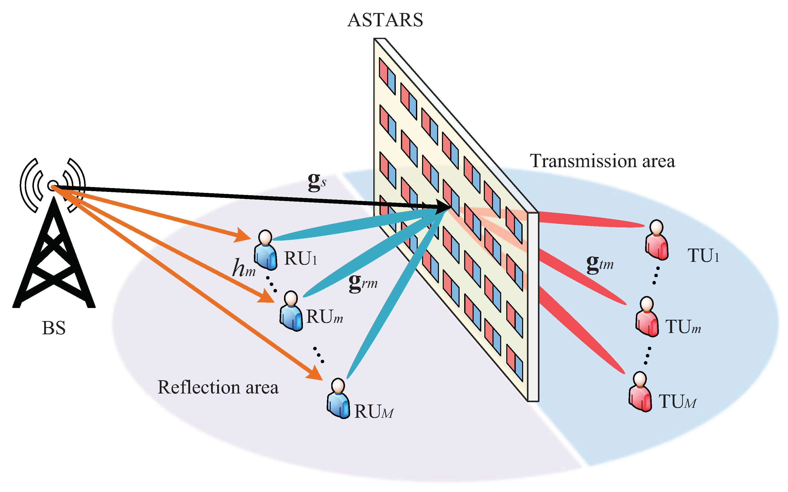
  • We propose an ASTARS-assisted downlink RSMA network with M reflection users (RUs) and M transmission users (TUs), where the direct link exists between BS and RUs while the link between BS and TUs is blocked. We derive the exact outage probability expressions of R U m and T U m with imperfect/perfect SIC for ASTARS-RSMA networks over cascaded Rician fading channels. We further demonstrate that the outage performance of R U m with imperfect/perfect SIC exceeds that of T U m when the reflection coefficient is larger.
  • We further derive the asymptotic outage probability expressions of R U m and T U m with imperfect/perfect SIC by applying Taylor series and the Laplace transform. On this basis, we calculate the diversity orders of R U m and T U m with imperfect/perfect SIC. We confirm that the diversity orders of both R U m and T U m with imperfect SIC are z e r o . Conditioned on the perfect SIC scenario, the diversity orders of both R U m and T U m are related to the number of ASTARS elements, while R U m ’s diversity order is also to the one direct link;
  • We evaluate the system throughput and EE of ASTARS-RSMA networks with imperfect/perfect SIC in the delay-limited mode. We confirm that the system throughput of ASTARS-RSMA with imperfect SIC is lower than the expected upper limit due to the impact of residual interference caused by imperfect SIC. Moreover, we reveal that the EE of ASTARS-RSMA with perfect SIC is superior to that of ASTARS-RSMA with imperfect SIC, and the EE improves with an increase in the number of ASTARS elements.
  • We contrast the outage probability, system throughput, and EE of ASTARS-RSMA with those of PSTARS-RSMA and ASTARS-NOMA. We confirm that the ASTARS-RSMA has a superior performance compared to PSTARS-RSMA and ASTARS-NOMA in terms of outage probability, system throughput and EE. We reveal that despite the fact that ASTARS increases power consumption compared to PSTARS, it can bring about further EE improvements in the RSMA network.

1.3. Organization and Notation

Organization: Section 2 introduces the system model of the ASTARS-RSMA network. The outage probability expressions of R U m and T U m with imperfect/perfect SIC and system throughput are evaluated in Section 3. The diversity and EE analysis are analyzed in Section 4 and Section 5, respectively. Section 6 presents simulation results and discussions, then Section 7 gives the conclusion of this paper. Finally, mathematical proofs are presented in Appendix A, Appendix B and Appendix C.
Notation: The conjugate transpose and absolute value of A are denoted by A H and A , respectively. The cumulative distribution function (CDF) and probability density function (PDF) of X are denoted by F X · and f X · , separately. L · denotes Laplace transform.

2. System Model

2.1. Device Deployment Location

As shown in Figure 1, we consider an ASTARS-assisted downlink RSMA communication network, where the ASTARS amplifies the signals from the base station (BS) and then reflects or transmits the signals to 2M users. By adjusting the phase of ASTARS, the half region where the BS is located is defined as the reflection area, while the other side is defined as the transmission area. Specifically, M users are distributed in the reflection area and transmission area, respectively. The m-th reflection user and m-th transmission user are denoted by R U m and T U m , respectively. Assume that ASTARS contains L elements and that both BS and users are equipped with a single antenna. We assume that the impacts of simultaneous receptors in the transmission area and solar irradiance on the network are minimal and can be neglected. The hardware structure of ASTARS introduces active amplifiers, which can reflect and transmit signals while amplifying singles [22,23,24]. Specifically, the incident electromagnetic waves undergo polarization evolution after passing through ASTARS, resulting in transmitted and reflected signals. They can be equated with waves radiated out by time-varying surface equivalent currents and magnetic currents [41]. We suppose that the direct link from the BS to T U m is unavailable or even enters a total outage status due to the significant blockage and complex wireless environment. BS can communicate with RUs through the direct link. The complex channel parameters of BS to ASTARS, BS to R U m , ASTARS to R U m and T U m are expressed as g s , h m , g r m and g t m , respectively. Due to the introduction of ASTARS, all channels of the ASTARS-RSMA networks are considered as Rician fading channels. The cascade complex channel parameters from the BS to ASTARS, and then to R U m and T U m are denoted by g r m H Θ r g s and g t m H Θ t g s , respectively. Assume that the reflection and transmission coefficients for each ASTARS element are defined as β η r e j θ r l and β η t e j θ t l , respectively. Θ ϕ = β η ϕ diag e j θ ϕ 1 , , e j θ ϕ L correspond to ASTARS’s reflection and transmission phase-shifting amplification matrices, where ϕ r , t . Assume that ASTARS is operating in ES mode [12]. The reflection and transmission amplitude coefficients are denoted by η r and η t and they satisfy relation η r + η t 1 . θ r l , θ t l 0 , 2 π corresponds to the phase shift of the l-th element in the transmission and reflection responses. Since the transmission and reflection phase shifts are controlled by two distinct phase shifters, θ r l and θ t l may be modified individually. For the convenience of analysis, assume that each ASTARS element has the same amplification factor β and β > 1 .

2.2. User’s Received Signal Model

In ASTARS-RSMA networks, the BS divides the signals of 2M users into one common message and 2M private messages, and then sends them to all users simultaneously. Therefore, the composite signal sent by the BS can be expressed as
X Σ = a c P s a x c + m = 1 M a r m P s a x r m + a t m P s a x t m ,
where the transmit power of BS is denoted by P s a and the messages of R U m and T U m and the common message are denoted by x r m , x t m and x c , respectively. a c , a r m and a t m separately denote the power allocation factor of R U m , T U m and the common message, and a c + m = 1 M a r m + a t m = 1 .
R U m receives the amplified and reflected signals from the BS to ASTARS, and the signals through the direct link. Due to the introduction of active devices, R U m is subject to thermal noise. At this moment, the received signal expression of R U m is written as
y r m = h m + g r m H Φ r g s X Σ + g r m H Θ r n t h + n ˜ r ,
where n ˜ r C N 0 , σ 0 2 stands for white Gaussian noise and its noise intensity is σ 0 2 . The thermal noise matrix generated by active elements is denoted by n t h = n t h 1 , , n t h l , , n t h L H and n t h l C N 0 , σ t h 2 . The complex channel parameters of BS to ASTARS, BS to R U m and ASTARS to R U m are expressed as g s = g s 1 , , g s L H , g s l = ω d s α 1 κ + 1 κ + 1 g ˜ s l , g r m = g r m 1 , , g r m L H , h m = ω d m α 1 κ + 1 κ + 1 h ˜ m and g r m l = ω d r m α 1 κ + 1 κ + 1 g ˜ r m l . g ˜ r m l , h ˜ m and g ˜ s l follow the complex Gaussian distribution C N 0 , 1 . The Rician factor is denoted by κ , the path-loss exponent is denoted by α and ω denotes the path loss. The distances from BS to ASTARS, BS to R U m and ASTARS to R U m are expressed as d s , d m and d r m , respectively.
T U m receives the amplified and transmitted signals from BS to ASTARS, and the thermal noise generated by the active devices. Therefore, the received signal expression of T U m is written as
y t m = g t m H Θ t g s X Σ + g t m H Θ t n t h + n ˜ t ,
where n ˜ t C N 0 , σ 0 2 stands for white Gaussian noise and its noise intensity is σ 0 2 . The complex channel parameters of ASTARS to T U m is denoted by g t m = g t m 1 , , g t m L H , where g t m l = ω d t m α 1 κ + 1 κ + 1 g ˜ t m l and g ˜ t m l C N 0 , 1 . d t m stands for the distance from ASTARS to T U m .
Based on the RSMA protocol, all users treat all private messages as interference to decode the common message x c . Thus, the corresponding signal-plus-interference-to-noise ratios (SINRs) of R U m and T U m are written as
γ r m c = a c P s a h m + g r m H Θ r g s 2 1 a c P s a h m + g r m H Θ r g s 2 + g r m H Θ r n t h 2 + σ 0 2
and
γ t m c = a c P s a g t m H Θ t g s 2 1 a c P s a g t m H Θ t g s 2 + g t m H Θ t n t h 2 + σ 0 2 ,
respectively.
After common message x c has been successfully decoded, users decode their own signals by treating other users’ private messages as interference. Considering the effect of imperfect SIC, the SINRs of R U m and T U m decoding their own signal are, respectively, written as
γ r m = a r m P s a h m + g r m H Θ r g s 2 P s a h m + g r m H Θ r g s 2 χ r m + g r m H Θ r n t h 2 + Δ g r e 2 P s a + σ 0 2
and
γ t m = a c P s a g t m H Θ t g s 2 P s a g t m H Θ t g s 2 χ t m + g t m H Θ t n t h 2 + Δ g r e 2 P s a + σ 0 2 ,
where χ r m = m = 1 M a t m + i = 1 , i m M a r i , χ t m = m = 1 M a r m + i = 1 , i m M a t i and g r e C N 0 , σ r e 2 denotes the residual interference caused by imperfect SIC; Δ = 0 indicates the perfect SIC scenario and Δ = 1 indicates an imperfect SIC scenario.

2.3. Channel Statistics

The channel statistical characteristics of cascade Rician and Rician channels are given in this section, and they will be used in the next section to research the outage probability of ASTARS-RSMA networks.
The channel gains between BS and R U m , i.e., h m , follow the Rician distribution, and the PDF and CDF of h m is written as
f h m x = 2 x κ + 1 d m α ω 1 e x 2 κ + 1 d m α ω 1 + κ I 0 2 x κ 2 + κ d m α ω 1
and
F h m x = 1 Q 2 κ , x 2 κ + 2 d m α ω 1 ,
where Q u , v = v x e x 2 + u 2 2 I 0 u x d x stands for the generalized Marcum Q-function [42] and I 0 · is the first kind z e r o order modified Bessel function [43]. With the ability of ASTARS to independently adjust the reflected and transmitted phase shifts, we can obtain the optimal cascade channel gains. Therefore, g ϕ m H Θ ϕ g s can be rewritten as β η ϕ l = 1 L g ϕ m l g s l . Let X ϕ = β η ϕ l = 1 L g ϕ m l g s l and X ϕ l = β η ϕ g ϕ m l g s l . Firstly, the PDF of X ϕ l is given by [44]
f X ϕ l x = 4 a = 0 b = 0 κ + 1 a + b + 2 x a + b + 1 κ a + b + 2 a ! 2 b ! 2 e 2 κ Ξ ϕ a + b K a b 2 x κ + 1 Ξ ϕ 1 ,
where Ξ ϕ = ω β η ϕ d ϕ m d s α 2 , K a · denotes the second kind a order modified Bessel function [43]. To evaluate the statistical properties of X ϕ , we provide the mean and variance of X ϕ l as
E ϕ l = Ξ ϕ π e κ 4 κ + 1 1 + κ I 0 κ 2 + κ I 1 κ 2 2
and
V ϕ l = Ξ ϕ 2 1 π 2 e 2 κ 16 κ + 1 2 1 + κ I 0 κ 2 + κ I 1 κ 2 4 ,
respectively.
The PDF and CDF of X ϕ can be characterized by E ϕ l and V ϕ l as
f X ϕ x = 1 λ ϕ Ω ϕ Γ Ω ϕ x Ω ϕ 1 e x λ ϕ
and
F X ϕ x = 1 Γ Ω ϕ γ Ω ϕ , x λ ϕ ,
where Ω ϕ = L E ϕ l 2 V ϕ l 1 , λ ϕ = V ϕ l E ϕ l 1 , Γ · stands for the gamma function and γ μ , x stands for the lower incomplete Gamma function [43].

3. Outage Analysis

In this section, we separately derive the outage probability expressions of R U m and T U m for the ASTARS-RSMA network, where the imperfect/perfect SIC scenarios are considered. On this basis, we further deduce the asymptotic outage probability expressions and diversity orders of R U m and T U m .

3.1. R U m ’s Outage Probability

The outage event at R U m includes two situations: (1) common message x c is not decoded; (2) R U m successfully decodes common message x c , but cannot decode its own message x r m . Thus, the outage event of R U m can be defined as
P r m = Pr γ r m c < γ ¯ c + Pr γ r m c > γ ¯ c , γ r m < γ ¯ r m ,
where γ ¯ c = 2 R ¯ c 1 and γ ¯ r m = 2 R ¯ r m 1 separately denote target SNR for decoding x c and x r m . The target rate for decoding R U m ’s message and the common message is denoted by R ¯ r m and R ¯ c , respectively.
Theorem 1.
Conditioned on an imperfect SIC scenario, i.e., Δ = 1 , the expression of R U m ’s outage probability for ASTARS-RSMA is
P r m i p S I C π u = 1 U r 1 x u 2 1 e r σ r e 2 2 U Γ Ω r λ r Ω r 1 Q 2 κ , r 1 1 2 x u + 1 2 κ + 2 d m α ω × e 1 2 λ r x n + 1 r 1 2 x u + 1 r Ω r 1 + π v = 1 V u = 1 U Φ v ψ r τ r ϑ r τ r Ω r 1 2 U Γ Ω r e r σ r e 2 λ r Ω r × e ϑ r τ r λ r 1 Q 2 κ , ψ r τ r ϑ r τ r 2 κ + 2 d m α ω 1 ,
where r = γ ¯ c ν r β η r + σ 0 2 a c P s a γ ¯ c P s a 1 a c , ν r = L ω σ t h 2 d r m α L κ + 1 κ + 1 , ψ r y = γ ^ r m ν r β η r + Δ y P s a + σ 0 2 P s a a c γ ^ r m χ r m , ϑ r y = x u + 1 ψ r y 2 , x u = cos π u 1 2 U 1 , τ r = σ r e 2 y v + r , y v stands for the Laguerre polynomial’s v-th zero point and the v-th weight is denoted by Φ v = V ! 2 y v L V + 1 y v 2 [45]. The parameters U and V ensure a balance between accuracy and complexity.
Proof. 
See Appendix A.  □
Corollary 1.
Conditioned on the perfect SIC scenario, i.e., Δ = 0 , the expression of R U m ’s outage probability for ASTARS-RSMA is given by
P r m p S I C u = 1 U π 1 x u 2 e 1 2 λ r ζ r x u + 1 2 U Γ Ω r λ r Ω r ε Ω r 1 Q 2 κ , ζ r 1 1 2 x u + 1 2 κ + 2 d m α ω ,
where ε = ζ r x u + 1 2 and ζ r = γ ^ r m ν r β η r + σ 0 2 P s a a c γ ^ r m χ r m .
Remark 1.
In the ASTARS-RSMA network, the power-allocation factors and target rates satisfy the following constraints, (1) 1 α c γ ¯ c < α c and (2) 1 α c α ϕ m γ ¯ r m < α ϕ m , which can ensure that the users’ performance remains within the effective range; otherwise, the system will always be in an outage state.

3.2. T U m ’s Outage Probability

Similar to R U m ’s outage event, the outage event of T U m can be defined as
P t m = Pr γ t m c < γ ¯ c + Pr γ t m c > γ ¯ c , γ t m < γ ¯ t m ,
where γ ¯ t m = 2 R ¯ r m 1 denotes the target SNR for decoding x t m . The target rate for decoding T U m ’s message is denoted by R ¯ t m .
Theorem 2.
Conditioned on an imperfect SIC scenario, i.e., Δ = 1 , the expression of T U m ’s outage probability for ASTARS-RSMA is
P t m i p S I C 1 e t σ r e 2 Γ Ω t γ Ω t , t λ t + v = 1 V Φ v e t σ r e 2 Γ Ω t γ Ω t , ψ t τ t λ t ,
where t = γ ¯ c ν t β η t + σ 0 2 a c P s a γ ¯ c P s a 1 a c , ν t = L ω σ t h 2 d t m α L κ + 1 κ + 1 , ψ t y = γ ^ t m ν t β η t + Δ y P s a + σ 0 2 P s a a c γ ^ t m χ t m and τ t = σ r e 2 y v + t .
Proof. 
See Appendix B.  □
Corollary 2.
Conditioned on the perfect SIC scenario, i.e., Δ = 0 , the expression of T U m ’s outage probability for ASTARS-RSMA is
P t m p S I C = 1 Γ Ω t γ Ω t , 1 λ t γ ^ t m ν t β η t + σ 0 2 P s a a c γ ^ t m χ t m .

3.3. Delay-Limited Mode

Delay-limited mode means that the system throughput depends on the outage probability at a fixed target data rate [46]. When an outage event occurs during the data-transmission phase, it means that the data transmission has failed and a retransmission needs to be initiated. In light of the above explanations, the system throughputs of ASTARS-RSMA with imperfect/perfect SIC in delay-limited mode are written as
R l i m Υ = 1 P r m Υ R ¯ r m + 1 P t m Υ R ¯ t m ,
where Υ p S I C , i p S I C is obtained from (16), (17), (19) and (20).

4. Diversity Analysis

The diversity order is an important performance metric in wireless communication systems; it is used to quantify the reliability and quality of signals obtained through multiple antennas or spatial paths. A larger diversity order indicates that the outage probability of the system decreases more quickly with increasing transmit power, which is more robust to fading loss [47]. The diversity order can be expressed as
d = lim P s a log P ϕ m P s a log P s a ,
where P ϕ m P s a stands for the asymptotic expressions of outage probability in the high SNR area. Thus, the key to calculating the diversity order of ASTARS-RSMA is to derive asymptotic expressions of outage probability for R U m and T U m , which are given by the following corollaries.

4.1. R U m ’s Diversity Order

Corollary 3.
Conditioned on an imperfect SIC scenario and P s a , an asymptotic expression of R U m ’s outage probability for ASTARS-RSMA is written as
P r m , i p S I C v = 1 V u = 1 U π Φ v ψ ˜ r τ ˜ r ϑ ˜ r τ ˜ r Ω r 2 U Γ Ω r λ r Ω r e ϑ ˜ r τ ˜ r λ r 1 1 Q 2 κ , ϖ 2 κ + 2 d m α ω ,
where ϑ ˜ r y = x u + 1 ψ ˜ r y 2 , ψ ˜ r y = Δ y γ ^ r m , τ ˜ r = σ r e 2 y v and ϖ = ψ ˜ r τ ˜ r ϑ ˜ r τ ˜ r .
Remark 2.
Upon substituting (23) into (22), we can calculate the diversity order of R U m for ASTARS-RSMA under the imperfect SIC scenario as z e r o . This is due to the effect of residual interference caused by imperfect SIC.
Corollary 4.
Conditioned on the perfect SIC scenario and P s a , an asymptotic expression of R U m ’s outage probability for ASTARS-RSMA is written as
P r m , p S I C = 2 Λ κ + 1 2 L + 1 d r m d s L α ζ r L + 1 ω 2 L + 1 d m α e κ β η r L 2 L + 2 ! ,
where Λ = 2 F 1 2 , 1 2 ; 5 2 ; 1 16 3 e 2 κ L , τ ˜ r = σ r e 2 y v and 2 F 1 · , · ; · ; · stands for the ordinary hypergeometric function.
Proof. 
See Appendix C.  □
Remark 3.
Upon substituting (24) into (22), we can calculate the diversity order of R U m for ASTARS-RSMA under the perfect SIC scenario as L + 1 . This suggests that the R U m ’s diversity order with perfect SIC is correlated with the number of ASTARS elements and the direct link.

4.2. T U m ’s Diversity Order

Corollary 5.
Conditioned on the imperfect SIC scenario and P s a , an asymptotic expression of T U m ’s outage probability for ASTARS-RSMA is written as
P t m , i p S I C v = 1 V Φ v 1 Γ Ω t γ Ω t , ψ ˜ t σ r e 2 y v λ t ,
where ψ ˜ t y = Δ y γ ^ t m .
Remark 4.
Upon substituting (25) into (22), we can calculate the diversity order of T U m for ASTARS-RSMA under the imperfect SIC scenario as z e r o , which leads to the same conclusion as Remark 2.
Corollary 6.
Conditioned on the perfect SIC scenario and P s a , an asymptotic expression of T U m ’s outage probability for ASTARS-RSMA is written as
P t m , p S I C = Λ ζ t L κ + 1 2 L d t m d s L α 2 L ω 2 L β η t L 2 L 1 ! ,
where ζ t = γ ^ t m ν t β η t + σ 0 2 P s a a c γ ^ t m χ t m .
Proof. 
The proof is similar to Appendix C.  □
Remark 5.
Upon substituting (26) into (22), we can calculate the diversity order of T U m for ASTARS-RSMA under the imperfect SIC scenario as L, which is only correlated with the number of ASTARS elements.

5. EE Analysis

The energy efficiency of a communication system is its ability to transmit or receive information while minimizing energy consumption. It is a measure of how effectively the system utilizes the energy resources to achieve reliable communication. The EE expression of ASTARS-RSMA can be given by
E e = R l i m Υ P t o t a ,
where P t o t a denotes the total power consumption of the ASTARS-RSMA network and R l i m Υ is obtained from (21).
The total power consumption of the ASTARS-RSMA network, i.e., P t o t a , consists of several parts, which can be expressed as
P t o t a = P s a + P r a + L P c + P d ,
where P s a stands for transmit power consumed by BS and P r a indicates the output signal power of ASTARS. P c and P d indicate the power consumption of the phase shift controller and amplifier in each ASTARS element, respectively.

6. Simulation Results

In this section, we provide simulation and theoretical results for the ASTARS-RSMA network. We assume that the networks contain four users, i.e., M = 2, and the power allocation factors for common and private information are set to a c = 0.2 and a ϕ m = 0.2 . Table 1 summarizes the simulation parameters [19,23,24] used in this paper, in which BPCU is short for bit per channel use. The accuracy–complexity trade-off parameters are set to U = V = 100 . To illustrate the performance characteristics of the ASTARS-RSMA network, we choose the PSTARS-RSMA and ASTARS-NOMA networks as baselines for comparison. In particular, the ASTARS-RSMA and PSTARS-RSMA networks are set to have the same total power consumption, and the total power consumption of the PSTARS-RSMA network is defined as P t o t p = L P c + P s p . Regarding the practical electronic application of ASTARS, a feasible hardware model is detailed in [22], where the reflection and transmission coefficients for each ASTARS element can be considered independent. Based on this hardware model, we mainly study some basic issues including the influence of ASTARS element number, amplification factor and reflection/transmission coefficients on the performance of ASTARS-RSMA network.

6.1. Outage Analysis

Figure 2 shows the outage probability of ASTARS-RSMA versus total system power consumption, where ASTARS-NOMA was selected as the comparison baseline. The outage probability curves of R U m and T U m under imperfect/perfect SIC scenarios are drawn from (16), (17), (19) and (20). We can observe that the Monte Carlo simulation results can perfectly coincide with the theoretical results, which shows the accuracy of the expressions we derived in Section 3. The asymptotic outage probability is indicated by the blue dotted lines. We can observe that the outage probability curves approach the asymptotic curves at high SNRs P s a , which shows the accuracy of the approximation we used. It can be observed that R U m has better outage performance than T U m . This is because R U m receives the direct signal from BS in addition to the signal from ASTARS, and we set a larger reflection coefficient to allocate more energy to R U m . Conditioned on an imperfect SIC scenario, one phenomenon is that the outage probability appears to exhibit an error floor in the high SNR region. This limitation in performance improvement is caused by the residual interference generated by the imperfect SIC. Therefore, improving the imperfect SIC mechanism is crucial in RSMA networks. In addition, the outage performance of ASTARS-RSMA is better than that of ASTARS-NOMA in both imperfect/perfect SIC scenarios. This is attributed to the fact that compared with NOMA’s full interference decoding, RSMA allocates part of the power for common information to achieve partial interference decoding, which has higher spectral efficiency.
In Figure 3, we present the outage probability of ASTARS-RSMA versus amplification factors with P s t o t = 30 (dBm), where PSTARS-RSMA is set as the comparison baseline. It can be seen that the outage performance of ASTARS-RSMA is better than that of PSTARS-RSMA. This is explained by the fact that ASTARS dedicates a portion of the total power to amplifying the signal, thus improving the decoding SINR. This phenomenon suggests that ASTARS has the ability to compensate for the loss of multiplicative fading. Another phenomenon is that increasing the amplification factor enhances the outage performance of ASTARS-RSMA. However, when the amplification factor exceeds 50, the outage performance stops increasing. This is caused by the fact that ASTARS amplifies the signal while also enhancing the thermal noise interference, and they attain equilibrium after the amplification factor exceeds 50. This leads to the generation of an amplification factor invalid region.
In Figure 4, we show the outage probability of ASTARS-RSMA versus the quantity of ASTARS elements L with P t o t a = 20 (dBm) and σ t h 2 = 50 (dBm). We can see from Figure 4 that increasing the number of ASTARS/PSTARS elements by a certain amount can effectively improve outage performance. This is attributed to the fact that increasing L boosts the diversity order of the ASTARS-RSMA network, which enhances the robustness of the network to path fading. This conclusion is consistent with the analysis in Remarks 3 and 5. However, the outage performance of ASTARS progressively decreases as L is greater than 50, thus performing worse than PSTARS-RSMA. This is the result of more active devices causing stronger thermal noise, which impacts the signal decoding. Therefore, the ASTARS-RSMA network is advantageous only when the number of elements is not too large, which illustrates the limitations of ASTARS-RSMA with respect to improving network performance.
Figure 5 plots the outage probability of ASTARS-RSMA versus the reflection amplitude coefficient with σ r e 2 = 65 (dBm), P t o t a = 35 (dBm) and β = 10 . One phenomenon is that as η r increases, the outage probability of R U m decreases while the outage probability of R U m increases. This opposite trend is due to the fact that η r and η t are limited by the conservation of energy, i.e., η r + η t = 1 . Therefore, the ASTARS-RSMA network has the flexibility to adjust the performance of users located in different service areas in the network.

6.2. System Throughput Analysis

Figure 6 displays the system throughput of ASTARS-RSMA versus total system power consumption, where the impact of different path-loss exponents on system throughput is considered. The system throughput curves are drawn from (21). We can observe that the system throughput of ASTARS-RSMA outperforms PSTARS-RSMA in delay-limited mode. The reason is that the users’ probability of outage in delay-limited mode is the main factor affecting the magnitude of the system throughput. Another phenomenon is that the system throughput of the ASTARS-NOMA network cannot reach the expected performance upper limit in the case of imperfect SIC. This is attributed to the fact that the users are affected by residual interference in the imperfect SIC mechanism, limiting the system performance improvement with transmit power. Moreover, we can see from Figure 6 that the system throughput of the ASTARS-RSMA network decreases significantly with the increase in path-loss exponent α . This is because α represents the rate at which signal power decays with distance, and a larger α leads to faster signal power decay. Therefore, accurate estimation of α is essential for proper network planning, coverage analysis and link budgeting in wireless communication systems.

6.3. EE Analysis

In Figure 7, we present EE of ASTARS-RSMA versus total system power consumption, where PSTARS-RSMA is set as the comparison baseline. The EE curves of ASTARS-RSMA are drawn from (27). An observable phenomenon is that the EE of ASTARS-RSMA increases first and then decreases. The following two reasons can explain this phenomenon. (i) During the initial phase of transmit power increase, the increasing system throughput located in the molecule dominates Equation (27), which results in a boost of EE. (ii) Greater transmit power will not bring commensurate performance gains to the system. This results in a higher growth rate of the denominator in Equation (27) compared to the numerator, thereby reducing the EE of ASTARS-RSMA. Therefore, with the goal of green communication, we should use the optimal transmit power to ensure the highest EE in networks with different numbers of ASTARS elements. It can also be seen that the EE of ASTARS-RSMA is higher than that of PSTARS-RSMA. This indicates that despite the fact that the introduction of ASTARS increases energy consumption, it can bring positive gains to system EE.

7. Conclusions

In this paper, we introduced an ASTARS in a downlink RSMA network, where the performance of R U m and T U m is discussed in detail. More specifically, we derived the new exact and asymptotic outage-probability expressions of R U m and T U m with imperfect/perfect SIC over cascaded Rician fading channels. Conditioned on the imperfect/perfect SIC scenarios, we calculated the diversity orders of R U m and T U m . We confirmed that the residual interference induced by imperfect SIC leads to users’ z e r o -diversity order with error floor. The system throughput and EE of ASTARS-RSMA was evaluated in delay-limited mode. Simulation results indicate that ASTARS-RSMA outperforms PSTARS-RSMA in terms of outage probability and system throughput when the number of elements is not too large. Although the active devices consume more power, the performance gains they bring about enable the EE of ASTARS-RSMA to exceed that of PSTARS-RSMA. Based on an analysis of the simulation results, the advantages and disadvantages of PSTARS-RSMA, ASTARS-NOMA and the proposed ASTARS-RSMA are summarized in Table 2. A future research direction is the optimization of ASTARS’s configuration for maximizing the system throughput and EE of ASTARS-RSMA, where the impacts of simultaneous receptors in the transmission area and solar irradiance should be taken into account.

Author Contributions

Conceptualization, J.X. and X.Y.; methodology, J.X. and X.Y.; validation, J.X. and X.Y.; formal analysis, J.X., X.Y., Z.H., X.L. and W.X.; investigation, J.X. and X.Y.; resources, J.X. and X.Y.; writing—original draft preparation, J.X. and X.Y.; writing—review and editing, J.X., X.Y., Z.H., X.L. and W.X.; supervision, Z.H., X.L. and W.X.; project administration, X.Y.; funding acquisition, X.Y. All authors have read and agreed to the published version of the manuscript.

Funding

National Key Research and Development Program of China: Grant 2020YFB1807102; National Natural Science Foundation of China: Grant 62071052.

Institutional Review Board Statement

Not applicable.

Informed Consent Statement

Not applicable.

Data Availability Statement

Not applicable.

Conflicts of Interest

The authors declare no conflict of interest.

Appendix A

Proof of Theorem 1.
Before calculating the outage probability of R U m , we derive the PDF expression for Z = h m + X ϕ 2 . By combining (8), (9) and (13), the PDF expression for Z is calculated as
F Z z = Pr h m + X ϕ 2 z = Pr h m z X ϕ = 0 z 0 z x f h m y f X ϕ x d x d y = 0 z 1 Γ Ω r x Ω r 1 λ r Ω r e x λ r 1 Q 2 κ , z x 2 κ + 2 d m α ω 1 d x .
Carrying (4) and (6) into (15) and after some calculations, we can obtain
P r m i p S I C = Pr a c P s a Z 1 a c P s a Z + ν r β η r + σ 0 2 < γ ¯ c + Pr a c P s a Z 1 a c P s a Z + ν r β η r + σ 0 2 > γ ¯ c , a r m P s a Z P s a Z χ r m + ν r β η r + Δ g r e 2 P s a + σ 0 2 < γ ¯ r m = Pr Z < r + Pr r < Z < ψ r y 2 ,
where r = γ ¯ c ν r β η r + σ 0 2 a c P s a γ ¯ c P s a 1 a c , ψ r y = γ ^ r m ν r β η r + Δ y P s a + σ 0 2 P s a a c γ ^ r m χ r m and ν r = L ω σ t h 2 d r m α L κ + 1 κ + 1 denotes the interference intensity of the thermal noise.
Carrying f g r e 2 y = σ r e 2 e y σ r e 2 , F g r e 2 y = 1 e y σ r e 2 and (A1) into (A2), we can obtain
P r m i p S I C = F Z r + r f g r e 2 y F Z ψ r y 2 F Z r d y = F Z r F Z r F g r e 2 F g r e 2 r + r f g r e 2 y F Z ψ r y 2 d y = F Z r F g r e 2 r + 1 Γ Ω r r σ r e 2 e y σ r e 2 0 ψ r y x Ω r 1 λ r Ω r e x λ r × 1 Q 2 κ , ψ r y x 2 κ + 2 d m α ω 1 d x d y .
The Gauss–Chebyshev quadrature [45] is applied to dealing with the definite integral in (A3) and we can obtain
P r m i p S I C F Z r F g r e 2 r + r π ψ r y 2 U Γ Ω r λ r Ω r σ r e 2 e y σ r e 2 u = 1 U ϑ r y Ω r 1 e ϑ r y λ r × 1 Q 2 κ , ψ r y ϑ r y 2 κ + 2 d m α ω 1 1 x u 2 d y ,
where ϑ r y = x u + 1 ψ r y 2 and x u = cos π u 1 2 U 1 .
The above equation can be calculated via the Gauss–Laguerre quadrature [45] expression, i.e., b e a t f y d y = e a b a v = 1 V Φ v f y v a + b . After some mathematical calculations, we can obtain (16). The proof is complete. □

Appendix B

Proof of Theorem 2.
Upon substituting (5) and (7) into (18), and after some mathematical calculations, we can obtain
P t m i p S I C = F X t t + t f g r e 2 y F X t ψ t y 2 F X t t d y = F X t t F g r e 2 t + t f g r e 2 y F X t ψ t y 2 d y .
Combining f g r e 2 y = σ r e 2 e y σ r e 2 and (14), we can obtain
P r m i p S I C = 1 e t σ r e 2 Γ Ω t γ Ω t , t λ t + t σ r e 2 e y σ r e 2 1 Γ Ω t γ Ω t , ψ t y λ t d y .
By applying the Gauss–Laguerre quadrature expression, the above equation can be calculated as (19). The proof is complete. □

Appendix C

Proof of Corollary 4.
To calculate the asymptotic outage probability expression for R U m , we first compute the Laplace transform expression for the PDF of X ϕ l . By substituting (10) into the Equation (2.16.6.3) of [48], we can obtain
L f X ϕ l x s = a = 0 b = 0 π 4 a b + 1 s 1 + κ 2 a + 1 κ a + b Γ 2 a + 2 Γ 2 b + 2 Ξ ϕ a + b + 2 a ! 2 b ! 2 e 2 κ s + 2 1 + κ 2 a + 2 Γ a + 5 2 + b ,
where s = 2 F 1 2 a + 2 , a b + 1 2 ; a + b + 5 2 ; s 2 Ξ ϕ κ + 1 s + 2 Ξ ϕ κ + 1 .
When P s a implies that x 0 and s tends to infinity, and retaining the first term of the above series, we can obtain
L f X ϕ l 0 + x s = 2 F 1 2 , 1 2 ; 5 2 ; 1 16 1 + κ 2 3 Ξ ϕ 2 s 2 e 2 κ .
After calculating the Taylor series of f h m x at 0 point and performing Laplace transform, we can obtain
L f h m 0 + x s = 2 κ + 1 ω d m α e κ s 2 .
By employing the convolution theorem, the Laplace transform expression for the PDF of Z at high SNRs can be computed as
L f Z 0 + z s = 2 Λ L κ + 1 2 L + 1 d ϕ m d s L α ω 2 L + 1 d m α β η ϕ L e κ s 2 L + 2 .
After employing the Laplace inverse transform, the PDF of Z at high SNRs can be calculated as
f Z 0 + z = Λ L κ + 1 2 L + 1 d ϕ m d s L α z L ω 2 L + 1 d m α β η ϕ L e κ 2 L + 1 ! .
Upon substituting Δ = 0 into (6), we can obtain
γ r m = a r m P s a h m + g r m H Θ r g s 2 P s a h m + g r m H Θ r g s 2 χ r m + g r m H Θ r n t h 2 + σ 0 2 .
Upon substituting (A12) and (4) into (15), we can obtain
P r m p S I C = Pr a c P s a Z 1 a c P s a Z + ν r β η r + σ 0 2 < γ ¯ c + Pr a c P s a Z 1 a c P s a Z + ν r β η r + σ 0 2 > γ ¯ c , a r m P s a Z P s a Z χ r m + ν r β η r + σ 0 2 < γ ¯ r m = Pr Z < r + Pr r < Z < γ ^ r m ν r β η r + σ 0 2 P s a a c γ ^ r m χ r m = Pr Z < γ ^ r m ν r β η r + σ 0 2 P s a a c γ ^ r m χ r m = 0 ζ t f Z 0 + z d z .
Combining (A11) and (A13), we can obtain (24). The proof is complete. □

References

  1. Yang, P.; Xiao, Y.; Xiao, M.; Li, S. 6G wireless communications: Vision and potential techniques. IEEE Netw. 2019, 33, 70–75. [Google Scholar] [CrossRef]
  2. Chen, S.; Liang, Y.-C.; Sun, S.K.S.; Cheng, W.; Peng, M. Vision, requirements, and technology trend of 6G: How to tackle the challenges of system coverage, capacity, user data-rate and movement speed. IEEE Wirel. Commun. 2020, 27, 218–228. [Google Scholar] [CrossRef]
  3. You, X.; Wang, C.X.; Huang, J.; Gao, X.; Zhang, Z.; Wang, M.; Huang, Y.; Zhang, C.; Jiang, Y.; Wang, J.; et al. Towards6G wireless communication networks: Vision, enabling technologies, and new paradigm shifts. Sci. China Inf. Sci. 2021, 64, 110301. [Google Scholar] [CrossRef]
  4. Basar, E.; Di Renzo, M.; De Rosny, J.; Debbah, M.; Alouini, M.-S.; Zhang, R. Wireless communications through reconfigurable intelligent surfaces. IEEE Access 2019, 7, 116753–116773. [Google Scholar] [CrossRef]
  5. Wu, Q.; Zhang, R. Towards smart and reconfigurable environment: Intelligent reflecting surface aided wireless network. IEEE Commun. Mag. 2020, 58, 106–112. [Google Scholar] [CrossRef]
  6. Zhang, H.; Di, B. Intelligent omni-surfaces: Simultaneous refraction and reflection for full-dimensional wireless communications. IEEE Commun. Surv. Tutor. 2022, 24, 1997–2028. [Google Scholar] [CrossRef]
  7. Yang, L.; Yang, J.; Xie, W.; Hasna, M.O.; Tsiftsis, T.; Renzo, M.D. Secrecy performance analysis of RIS-aided wireless communication systems. IEEE Trans. Veh. Technol. 2020, 69, 12296–12300. [Google Scholar] [CrossRef]
  8. Keykhosravi, K.; Keskin, M.F.; Dwivedi, S.; Seco-Granados, G.; Wymeersch, H. Semi-passive3D positioning of multiple RIS-enabled users. IEEE Trans. Veh. Technol. 2021, 70, 11073–11077. [Google Scholar] [CrossRef]
  9. Yang, L.; Meng, F.; Zhang, J.; Hasna, M.O.; Renzo, M.D. On the performance of RIS-assisted dual-hop UAV communication systems. IEEE Trans. Veh. Technol. 2020, 69, 10385–10390. [Google Scholar] [CrossRef]
  10. Liu, Y.; Liu, X.; Mu, X.; Hou, T.; Xu, J.; Renzo, M.D.; Al-Dhahir, N. Reconfigurable intelligent surfaces: Principles and opportunities. IEEE Commun. Surv. Tutor. 2021, 23, 1546–1577. [Google Scholar] [CrossRef]
  11. Xu, J.; Liu, Y.; Mu, X.; Zhou, J.T.; Song, L.; Poor, H.V.; Hanzo, L. Simultaneously transmitting and reflecting intelligent omni-surfaces: Modeling and implementation. IEEE Veh. Technol. Mag. 2022, 17, 46–54. [Google Scholar] [CrossRef]
  12. Liu, Y.; Mu, X.; Xu, J.; Schober, R.; Hao, Y.; Poor, H.V.; Hanzo, L. STAR: Simultaneous transmission and reflection for 360° coverage by intelligent surfaces. IEEE Wirel. Commun. 2021, 28, 102–109. [Google Scholar] [CrossRef]
  13. Mu, X.; Liu, Y.; Guo, J.; Schober, R. Simultaneously transmitting and reflecting(STAR) RIS aided wireless communications. IEEE Trans. Wirel. Commun. 2022, 21, 3083–3098. [Google Scholar] [CrossRef]
  14. Zhang, S.; Zhang, H.; Di, B.; Tan, Y.; Renzo, M.D.; Han, Z.; Poor, H.V.; Song, L. Intelligent omni-surfaces: Ubiquitous wireless transmission by reflective-refractive metasurfaces. IEEE Trans. Wirel. Commun. 2022, 21, 219–233. [Google Scholar] [CrossRef]
  15. Björnson, E.; Özdogan, Ö.; Larsson, E.G. Intelligent reflecting surface versus decode-and-forward: How large surfaces are needed to beat relaying? IEEE Wirel. Commun. Lett. 2020, 9, 244–248. [Google Scholar] [CrossRef]
  16. Zhang, Z.; Dai, L.; Chen, X.; Liu, C.; Yang, F.; Schober, R.; Poor, H.V. Active RIS vs. passive RIS: Which will prevail in 6G? IEEE Trans. Commun. 2023, 71, 1707–1725. [Google Scholar] [CrossRef]
  17. Jian, M.; Alexandropoulos, G.C.; Basar, E.; Huang, C.; Liu, R.; Liu, Y.; Yuen, C. Reconfigurable intelligent surfaces for wireless communications: Overview of hardware designs, channel models, and estimation techniques. Intell. Converged Netw. 2022, 3, 1–32. [Google Scholar] [CrossRef]
  18. Bazrafkan, A.; Poposka, M.; Hadzi-Velkov, Z.; Popovski, P.; Zlatanov, N. Performance Comparison Between A Simple Full-Duplex Multi-Antenna Relay And A Passive Reflecting Intelligent Surface. IEEE Trans. Wirel. Commun. 2023. early access. [Google Scholar] [CrossRef]
  19. Zhi, K.; Pan, C.; Ren, H.; Chai, K.; Elkashlan, M. Active RIS versus passive RIS: Which is superior with the same power budget? IEEE Commun. Lett. 2022, 26, 1150–1154. [Google Scholar] [CrossRef]
  20. Dong, L.; Wang, H.-M.; Bai, J. Active reconfigurable intelligent surface aided secure transmission. IEEE Trans. Veh. Technol. 2022, 71, 2181–2186. [Google Scholar] [CrossRef]
  21. Tasci, R.A.; Kilinc, F.; Alexandropoulos, G.C. A new RIS architecture with a single power amplifier: Energy efficiency and error performance analysis. IEEE Access 2022, 10, 44804–44815. [Google Scholar] [CrossRef]
  22. Xu, J.; Zuo, J.; Zhou, J.T.; Liu, Y. Active simultaneously transmitting and reflecting(STAR)-RISs: Modelling and analysis. IEEE Commun. Lett. 2023. early access. [Google Scholar] [CrossRef]
  23. Ma, Y.; Li, M.; Liu, Y.; Wu, Q.; Liu, Q. Optimization for reflection and transmission dual-functional active RIS-assisted systems. IEEE Trans. Commun. 2023. early access. [Google Scholar] [CrossRef]
  24. Guo, Y.; Liu, Y.; Wu, Q.; Shi, Q.; Zhao, Y. Enhanced secure com-munication via novel double-faced active RIS. IEEE Trans. Wirel. Commun. 2023, 71, 3497–3512. [Google Scholar] [CrossRef]
  25. Giordani, M.; Polese, M.; Mezzavilla, M.; Rangan, S.; Zorzi, M. Toward 6G networks: Use cases and technologies. IEEE Commun. 2020, 58, 55–61. [Google Scholar] [CrossRef]
  26. Jaafar, W.; Naser, S.; Muhaidat, S.; Sofotasios, P.C.; Yanikomeroglu, H. Multiple access in aerial networks: From orthogonal and non-orthogonal to rate-splitting. IEEE Open J. Veh. Technol. 2020, 1, 372–392. [Google Scholar] [CrossRef]
  27. Mao, Y.; Dizdar, O.; Clerckx, B.; Schober, R.; Popovski, P.; Poor, H.V. Rate-Splitting Multiple Access: Fundamentals, Survey, and Future Research Trends. IEEE Commun. Surv. Tutor. 2022, 24, 2073–2126. [Google Scholar] [CrossRef]
  28. Khan, W.U.; Liu, J.; Jameel, F.; Sharma, V.; Jantti, R.; Han, Z. Spectral efficiency optimization for next generation NOMA-enabled IoT networks. IEEE Trans. Veh. Technol. 2020, 69, 15284–15297. [Google Scholar] [CrossRef]
  29. Rimoldi, B.; Urbanke, R. A rate-splitting approach to the gaussian multiple-access channel. IEEE Trans. Inf. Theory 1996, 42, 364–375. [Google Scholar] [CrossRef]
  30. Yang, Z.; Chen, M.; Saad, W.; Shikh-Bahaei, M. Optimization of rate allocation and power control for rate splitting multiple access(RSMA). IEEE Trans. Commun. 2021, 69, 5988–6002. [Google Scholar] [CrossRef]
  31. Yang, Z.; Chen, M.; Saad, W.; Xu, W.; Shikh-Bahaei, M. Sum-rate maximization of uplink rate splitting multiple access(RSMA) communication. IEEE Trans. Mob. Comput. 2020, 21, 2596–2609. [Google Scholar] [CrossRef]
  32. Mao, Y.; Clerckx, B.; Li, V.O.K. Rate-splitting multiple access for downlink communication systems: Bridging, generalizing, and outperforming SDMA and NOMA. EURASIP J. Wirel. Commun. Netw. 2018, 1, 133. [Google Scholar] [CrossRef] [PubMed]
  33. Bansal, A.; Singh, K.; Clerckx, B.; Li, C.-P.; Alouini, M.-S. Rate-Splitting Multiple Access for Intelligent Reflecting Surface Aided Multi-User Communications. IEEE Trans. Veh. Technol. 2021, 70, 9217–9229. [Google Scholar] [CrossRef]
  34. Gao, Y.; Wu, Q.; Chen, W.; Ng, D.W.K. Rate-Splitting Multiple Access for Intelligent Reflecting Surface-Aided Secure Transmission. IEEE Commun. Lett. 2023, 27, 482–486. [Google Scholar] [CrossRef]
  35. Shambharkar, D.; Dhok, S.; Singh, A.; Sharma, P.K. Rate-Splitting Multiple Access for RIS-Aided Cell-Edge Users With Discrete Phase-Shifts. IEEE Commun. Lett. 2022, 26, 2581–2585. [Google Scholar] [CrossRef]
  36. Katwe, M.; Singh, K.; Clerckx, B.; Li, C.-P. Rate Splitting Multiple Access for Sum-Rate Maximization in IRS Aided Uplink Communications. IEEE Trans. Wirel. Commun. 2023, 22, 2246–2261. [Google Scholar] [CrossRef]
  37. Dhok, S.; Sharma, P.K. Rate-Splitting Multiple Access With STAR RIS Over Spatially-Correlated Channels. IEEE Trans. Commun. 2022, 70, 6410–6424. [Google Scholar] [CrossRef]
  38. Katwe, M.; Singh, K.; Clerckx, B.; Li, C.P. Improved Spectral Efficiency in STAR-RIS Aided Uplink Communication using Rate Splitting Multiple Access. IEEE Trans. Wirel. Commun. 2023, 22, 5365–5382. [Google Scholar] [CrossRef]
  39. Liu, P.; Li, Y.; Cheng, W.; Dong, X.; Dong, L. Active Intelligent Reflecting Surface Aided RSMA for Millimeter-Wave Hybrid Antenna Array. IEEE Trans. Commun. 2023. early access. [Google Scholar] [CrossRef]
  40. Niu, H.; Lin, Z.; An, K.; Wang, J.; Zheng, G.; Al-Dhahir, N.; Wong, K.-K. Active RIS Assisted Rate-Splitting Multiple Access Network: Spectral and Energy Efficiency Tradeoff. IEEE J. Sel. Areas Commun. 2023, 41, 1452–1467. [Google Scholar] [CrossRef]
  41. Xu, J.; Liu, Y.; Mu, X.; Dobre, O.A. STAR-RISs: Simultaneous Transmitting and Reflecting Reconfigurable Intelligent Surfaces. IEEE Commun. Lett. 2021, 25, 3134–3138. [Google Scholar] [CrossRef]
  42. Cantrell, P.E.; Ojha, A.K. Comparison of generalized Q-function algorithms. IEEE Trans. Inf. Theory. 1987, 33, 591–596. [Google Scholar] [CrossRef]
  43. Gradshteyn, I.S.; Ryzhik, I.M. Table of Integrals, Series and Products, 6th ed.; Academic Press: New York, NY, USA, 2000. [Google Scholar]
  44. Simon, M.K. Probability Distributions Involving Gaussian Random Variables; Springer: New York, NY, USA, 2006. [Google Scholar]
  45. Hildebrand, E. Introduction to Numerical Analysis; Dover: New York, NY, USA, 1987. [Google Scholar]
  46. Zhong, C.; Suraweera, H.A.; Zheng, G.; Krikidis, I.; Zhang, Z. Wireless information and power transfer with full duplex relaying. IEEE Trans. Commun. 2014, 62, 3447–3461. [Google Scholar] [CrossRef]
  47. Laneman, J.; Tse, D.; Wornell, G. Cooperative diversity in wireless networks: Efficient protocols and outage behavior. IEEE Trans. Inf. Theory 2004, 50, 3062–3080. [Google Scholar] [CrossRef]
  48. Prudnikov, A.P.; Brychkov, Y.A.; Marichev, O.I. Integrals and Series, Vol. 1 and Vol. 2, Elementary Functions and Special Functions; Gordon & Breach Sci. Publ.: New York, NY, USA, 1986. [Google Scholar]
Figure 1. ASTARS-assisted downlink multi-user RSMA communication network.
Electronics 12 03815 g001
Figure 2. Outage probability of ASTARS-RSMA versus total system power consumption.
Electronics 12 03815 g002
Figure 3. Outage probability of ASTARS-RSMA versus amplification factors.
Electronics 12 03815 g003
Figure 4. Outage probability of ASTARS-RSMA versus the quantity of ASTARS elements L.
Electronics 12 03815 g004
Figure 5. Outage probability of ASTARS-RSMA versus the reflection amplitude coefficient.
Electronics 12 03815 g005
Figure 6. System throughput of ASTARS-RSMA versus total system power consumption.
Electronics 12 03815 g006
Figure 7. EE of ASTARS-RSMA versus total system power consumption.
Electronics 12 03815 g007
Table 1. Simulation Parameters of ASTARS-RSMA network.
Monte Carlo simulation times 10 6
Rician factor−7 (dB)
Target data rates R c = R ϕ m = 0.2 (BPCU)
Amplification factor β = 5
Amplitude coefficients η r = 0.8 and η t = 0.2
Quantity of ASTARS elements L = 10
Noise intensity σ r e 2 = σ 0 2 = 80 (dBm) and σ t h 2 = 65 (dBm)
Path-loss coefficients ω = 30 (dBm) and α = 2
Communication distances d ϕ m = 20 (m) and d m = d s = 30 (m)
ASTARS element power consumption P c = P d = 20 (dBm)
Table 2. A comparison of different downlink networks.
NetworkResist FadingSpectrum EfficiencyEnergy Consumption
ASTARS-RSMAStrongerHigherMore
ASTARS-NOMAStrongerLowerMore
PSTARS-RSMAWeakerHigherLess
Disclaimer/Publisher’s Note: The statements, opinions and data contained in all publications are solely those of the individual author(s) and contributor(s) and not of MDPI and/or the editor(s). MDPI and/or the editor(s) disclaim responsibility for any injury to people or property resulting from any ideas, methods, instructions or products referred to in the content.

