1. Introduction
The development of the CubeSat standard in 1999 started a new era in satellite applications. Low building and launching costs made space exploration available to a broad range of users, such as universities, private firms, and even amateurs. The nanosatellite platform may carry various payloads, such as communication transceivers, cameras for Earth and space observations, magnetic field sensors, etc.
An important aspect of every satellite mission is establishing a reliable communication link with the spacecraft. Traditionally, CubeSats use VHF, as well as UHF bands assigned to radio amateur communications. For this purpose, off-the-shelf amateur transceivers are usually installed at the ground station and no frequency reservations are required. Radio links are often based on the AX.25 protocol, which performs well for low-bit rate data communications, and is sufficient for tracking, telemetry, and control (TT&C) links.
However, when a nanosatellite hosts an advanced payload, e.g., a high-resolution camera, high-throughput links are required. For this purpose, CCSDS-compliant (CCSDS: Consultative Committee for Space Data Systems) communication systems operating in the S and X bands are often used. In most cases, the net data rate does not exceed 5 Mbps due to the limited channel bandwidth available in the S band. Much higher bit rates are possible in the X band; however, the systems become costly when the operating frequency is higher than 6 GHz and microwave electronic components are necessary.
The growing popularity of nanosatellites has pushed the International Telecommunication Union (ITU) to assign the frequencies 5830–5850 MHz (C band) to space-to-earth amateur communication (see, e.g., [
1]). Due to the lower operating frequency, the attenuation of the signal in the C band is lower than in the X band and it is less susceptible to, e.g., rain than in the S band. Another advantage is the fact that the hardware may be implemented using cheaper electronics, as compared to X-band transceivers, and the ground station can be based on less-expensive and popular off-the-shelf SDR modules, like USRP, HackRF, or bladeRF. Finally, the interference level from other satellite transmissions in this band is significantly lower than in the S band, due to limited number of satellites operating in the C band. However, all of the details of the system must be publicly available to allow the radio amateur community to freely decode the transmission, which may be an important disadvantage for some applications.
The original contribution of this paper is the application of the C band to broadband CubeSat communication. To our knowledge, there are no other CubeSat radio links operating in this band. Another important novelty is the link adaptation procedure, which operates without a real-time reverse link and selects the best (in terms of maximum throughput) transmission mode in advance, based on machine learning techniques.
The outline of the paper is as follows. After a short introduction, several broadband CubeSat communication systems are reviewed in
Section 2. In
Section 3, the basic concepts of the system developed at the Poznan University of Technology (PUT) are described. The following sections present modulation schemes (
Section 4), a synchronization subsystem (
Section 5), and finally, channel-coding and link-adaptation procedures (
Section 6) that have been adopted in the system.
Section 7 is devoted to the implementation of the system. Finally,
Section 8 summarizes the paper and indicates future work.
2. Related Works
In most CubeSat missions, TT&C communication links operate in the VHF/UHF bands. However, the 25 kHz channel limits the throughput to several kbps. In recent years, more and more sophisticated payloads have been installed onboard the nanosatellites; therefore, a lot of work has been devoted to the development of broadband CubeSat communication systems, especially for space-to-earth transmission. Below, some examples of such systems are briefly summarized.
Planet Labs Inc. developed the HSD2 satellite radio [
2] for 3U CubeSats, operating in the 300 MHz X-band channel. The transmitter uses a 1 W RF power output and a 15 dBi gain antenna. It consumes 50 W of DC power. The system uses DVB-S2 modulation and coding, providing roughly a 1.6 Gbps data rate when using two orthogonal circular polarizations simultaneously.
Syrlinks, jointly with CNES, has developed an N-XONOS transmitter module operating on the X band [
3]. The system is CCSDS-compliant with a useful information bitrate of up to 350 Mbps. It consumes 15 W of DC power at 2 W RF.
Other X-band and S-band transmitters are available from ENDUROSAT [
4]. They are DVB-S2/CCSDS-compliant products. The X-band module offers 150 Mbps with 2 W RF output power. The S-band module transmits 2 W of RF power and consumes 7 W of DC power, while the information data rate is limited to 17 Mbps.
The SRS-3 transceiver from Satlab A/S [
5] operates in the S band and can deliver up to 512 kbps or 212 kbps of uncoded and encoded data, respectively. It uses GMSK modulation together with concatenated coding (Reed–Solomon + convolutional). The transmit power is limited to 1 W and the module consumes 5 W of DC power. A popular CubeSat space protocol (CSP) is used at the link layer for compatibility with a range of onboard computers.
ISIS TXS is another example of an off-the-shelf S-band transmitter for the CubeSat downlink [
6]. It operates with up to 2 W of RF power while consuming 13 W of DC power. The system is CCSDS-compliant with a useful information bitrate of up to 4.3 Mbps. The selection of modulation schemes is limited to BPSK and OQPSK with maximum symbol rates of 10 Msps and 5 Msps, respectively.
Many university projects are also devoted to experiments with CubeSat satellites. Some examples are listed below. An amateur S-band CubeSat radio has been developed at California Polytechnic State University [
7]. It consumes 8 W of DC power at 2 W RF and operates in the 2.3 MHz channel, using spread-spectrum OQPSK modulation and data rates up to 2000 kbps.
Another high-speed S-band communication system for nanosatellites has been designed at the Universitat Politècnica de Catalunya [
8]. The proposed solution uses Atheros-based 2.4 GHz WiFi adapters as transceivers. Their open-source firmware makes necessary modifications possible for the user. Link robustness is achieved by applying concatenated LDPC and Reed–Solomon codes at the application layer and the system delivers roughly 6 Mbps of user throughput.
The only CubeSat communication system operating in the C band has been mentioned in [
9]; however, the paper is devoted to patch antenna design, and no details of the proposed system are presented.
3. System Concept
The idea of developing proprietary CubeSat broadband communication systems was born in 2018 when the MoU between PUT and the Kyiv Polytechnic Institute (KPI) was signed. The cooperation aimed at developing and launching a series of experimental nanosatellites. The payload may include optical sensors and other devices producing megabytes of data; therefore, a high-throughput radio link is required.
3.1. System Requirements and Link Budget
The satellites developed together with our partners, KPI and SatRev company, in the 6U/12U CubeSat standard host VHF/UHF TT&C radio links as a primary communication channel. A C-band communication subsystem is used as a broadband communication channel and meets the requirements shown in
Table 1.
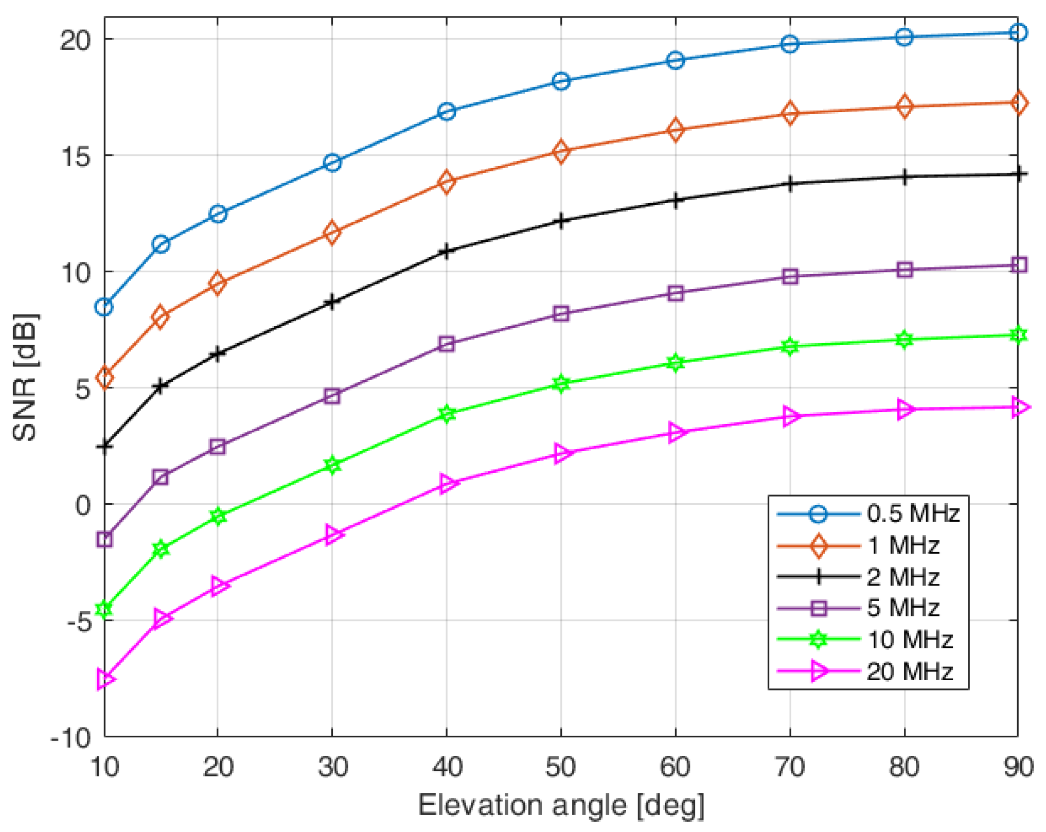
The system should operate at low elevation angles, implying low SNR values.
The satellites are designed to operate at low earth orbit (LEO) at an altitude of approximately 600 km (the exact orbit parameters will be known at the time of launching). The ground stations located at the PUT and KPI premises use 3 m tracking parabolic antennas with a gain of 46 dB. This allows to limit the transmit power of the satellite module to 1–2 W and still meet the link budget. Taking into account all other gains and losses not listed here, the link budget was calculated using the tool developed by AMSAT-UK [
10]. The predicted values of signal-to-noise ratios (SNR) versus elevation angle and signal bandwidth are presented in
Figure 1.
The actual SNRs can even be lower due to transmit and receive antenna misalignment and other system imperfections. The signal bandwidth can be selected individually for every visibility window (i.e., communication session) independently, based, e.g., on the maximum elevation angle during the satellite’s pass over a given ground station.
3.2. Proposed Physical Frame Structure
The broadband CubeSat communication systems under development must operate at very low SNRs, especially due to the limited transmit power and limited antenna size of the satellite. Another destructive effect typical of LEO satellite communications is an excessive Doppler shift resulting from the relative movement between the satellite (transmitter) and the ground station (receiver). For the proposed system, it can reach ±150 kHz with a Doppler frequency slope close to 1 kHz/s. Therefore, the application of efficient synchronization procedures and effective coding schemes is essential. In the following, the proposed physical frame structure is shown.
Typically, the transmission frame in the physical layer consists of training symbols interleaved with user data symbols. In the considered system, four different types of training sequences are defined to meet the performance requirements (see
Figure 2):
G_AMB preamble—used to train the automatic gain controller (AGC). The preamble is hardware-specific, and it is used based on the properties of the AD9364 integrated transceiver.
T_AMB preamble—used for time synchronization. The main purpose is to detect the start of a radio (physical) frame with the accuracy of a single sample. Since the transmission starts at the beginning of the satellite visibility window (i.e., at a low elevation angle), the SNR is very low and the procedure must be very robust.
F_AMB preamble—necessary for fine carrier frequency offset (CFO) estimation. CFO is roughly compensated for based on the values calculated from the orbital parameters and time epoch, a solution typically used in VHF/UHF CubeSat communication.
P_AMB midamble—in CubeSat communication, the Doppler shift changes during the satellite visibility window. Therefore, after the initial CFO estimate, the phase change must be tracked and compensated for. Midambles are interleaved with user data (i.e., fragments of code words); different midamble sequences are used to indicate the current code rate (due to adaptive coding).
Figure 2.
The radio (physical) frame structure.
Figure 2.
The radio (physical) frame structure.
The duration of the radio frame is ∼1 s, which is a compromise between the efficiency of the physical layer and the typical duration of the satellite visibility window (typically between 1 and 10 min). However, it can be modified together with other parameters (e.g., bandwidth and code rate) during system operation to meet specific conditions/requirements.
4. Selection of Modulation Scheme
There are several factors that must be taken into account in the selection of a modulation scheme in a CubeSat system, namely energy efficiency, peak-to-average power ratio (PAPR), spectral properties of the modulated signal, computational requirements of the transmitter and receiver, and the offered data rate in a given bandwidth. The first two constraints imply the consideration of two candidate modulations, namely Gaussian minimum shift keying (GMSK) and offset quadrature phase shift keying (OQPSK). Both modulations are recommended by CCSDS [
11,
12].
In the selection of modulation to be applied in our system, both of them were investigated. One of the facts that had a substantial influence on the evaluation of the potentially applied modulations was also the ease of generating demodulator soft outputs in the form of log-likelihood ratios (LLR) or their approximations for each received bit. They are necessary because the applied channel code decoder needs to use soft inputs to achieve high decoding performance.
GMSK signals have excellent spectral properties and PAPR = 0 dB. For the desired flexibility due to the potential application of other modulation formats, we considered a linearized approximation of GMSK [
13]. Recall that GSMK is inherently a differential modulation (a new phase is selected with respect to the phase achieved in the previous modulation period); therefore, in order to avoid differential demodulation on the receiver side, a feedforward differential encoder, called the precoder, is applied in front of the GMSK modulator. Therefore, on the receiver side, the information symbols are detected on the basis of alternative switching of the in-phase and quadrature components [
14].
A GMSK modulator, also in its linearized form, introduces inter-symbol interference (ISI), as its baseband shaping pulse lasts for a few modulation symbol periods. On the receiver side, a filter matched to it is usually applied, so sequential detection is a typical solution for this case. In the investigation of the GMSK-based system, the Ungerboeck sequential detector [
15] has been adopted. The problem to be solved was the generation of LLR values needed by the channel code decoder. Several attempts have been made. The first was the adoption of the most popular solution proposed by Hagenauer and Hoeher [
16] for the Ungerboeck detector. It turned out that it did not work properly due to its approximated method of LLR calculations, which is acceptable for rather high SNRs. In our case, the designed CubeSat receiver should also work reliably for low SNR values. Much better performance was observed for the detector originally proposed in the US patent [
17] for GSM and EDGE detection with soft output. In general, due to inherent ISI, the generation of soft outputs requires additional calculations and resources at the receiver.
We have also evaluated the spectral properties of a linearized GMSK modulation and determined the data rates available for a given bandwidth of the CubeSat channels. For this purpose, the power spectral densities were calculated for different products of , where B is the 3 dB bandwidth of a Gaussian-shaped transmit pulse and T is the modulation interval.
In
Table 2, we show the normalized frequency
F for the level that is determined for several values of
.
F is the value of the normalized frequency at which the power spectral density (PSD) decreases by 30 dB with respect to its maximum. Based on this value, we can determine the maximum data symbol rate
R that could be applied for a given channel bandwidth. Denoting
, we have
, where
W is the assumed channel bandwidth. The following channel bandwidth values were selected: 1.25, 5, 10, and 20 MHz. Therefore, selecting the appropriate value of
influences the achievable symbol rate. Recall that
is used in the GSM system, and in
Table 2 we distinguish the achievable data rates and the PAPR value for
in bold.
The determined data rates are substantially decreased when preambles and midambles, as well as channel coding, are applied. Therefore, to fulfill the data rate requirements under the best propagation conditions, GSMK should be replaced by a modulation that carries more bits per symbol. Such a modulation could be 8-PSK with the same baseband pulse shape and the same spectral properties. However, the number of states in the sequential detector increases from
for GMSK to
for 8-PSK, where
L is the number of subsequent data symbols that influence the sequential detection algorithm. Thus, a sub-optimal detector, such as the M-algorithm [
18] with a manageable number of states, should be applied.
Within the project, an alternative solution in the form of OQPSK modulation is considered. The main advantage of this modulation is the transmission of two bits per data symbol, although, despite the applied precautions, its PAPR value is higher than for GMSK. Another important advantage of OQPSK over GSMK is that it requires a much simpler receiver if the propagation channel does not suffer from inter-symbol interference. For that reason, transmit and receiver filters feature square-root raised cosine characteristics. The parameter to choose is its rolloff factor , which determines the slope of the filter characteristics and has a consequence on the achievable symbol data rate in the given channel bandwidth.
In
Table 3, similar parameters for the OQPSK modulation are presented to those shown in
Table 2 for GMSK. As before,
F is the value of the normalized frequency at which PSD decreases by 30 dB with respect to its maximum. Due to the fact that each data symbol carries two bits, the data rate is
.
The values of potential bit rates have to be treated indicatively only. In reality, the data rates are lower due to the application of preambles and midambles. The channel code significantly decreases the bit data rate of the user, depending on the applied coding rate.
In the process of modulation selection, we also took into account the estimated bit error rate at the detector output for the investigated transmitter and receiver configurations. In the system model considered, the sampling rate was four times higher than the modulation rate. BER estimation was performed for a linearized GMSK with parameter
and for OQPSK with square-root raised cosine filter characteristics with
. In the GSMK receiver, the filter matched to the pulse shape was applied, followed by the Ungerboeck sequential detector. A standard OQPSK receiver was applied with the receiver filter matched to the transmit pulse shape mentioned above and employed in the OQPSK transmitter. For the selected system configurations and distortion caused by additive white Gaussian noise (AWGN), both modulations resulted almost in the same BER curves plotted as a function of
. It turned out during our investigations that the GMSK demodulator requires sequential detection with soft outputs, which are not easy to generate and require many additional computations and system resources, whereas soft outputs for the OQPSK demodulator can be calculated very efficiently. Because of the spectral shaping of OQPSK-modulated signals, the spectral efficiencies of both modulations are comparable. The only drawback of OQPSK with respect to the linearized GMSK is a higher PAPR value of the former by about 2.7 dB. However, the construction of the applied power amplifier onboard the CubeSat makes this parameter less important. On the other hand, OQPSK offers much higher data rates (almost twofold) than GMSK for most of the channel bandwidths. This results in much higher flexibility in the selection of channel coding rates and achievable user data rates. Therefore, finally, the OQPSK with roll-off factor
was selected for downlink transmission and the corresponding parameters are indicated in
Table 3 in bold.
5. Synchronization Subsystem
Synchronization is a necessary element of the receiver chain in a communication system in order to perform coherent demodulation. The performance of synchronization is crucial, especially in the considered burst-mode transmission, where the acquisition time needs to be kept as short as possible while operating in low SNR conditions. Furthermore, as the described system is intended to operate at high frequencies in the C band, a very high CFO due to the Doppler effect is expected. Thus, we propose a data-aided (DA) feedforward synchronization structure, where the whole procedure involves two-stage CFO tracking and correction, as well as symbol timing (ST) and carrier phase offset (CPO) estimation, performed in the following steps, as depicted in
Figure 3:
Coarse CFO estimation and correction based on the estimation of orbital parameters of the satellite [
19], where the Doppler shift can be estimated following the procedure presented in [
20] and explained in
Section 3.
Frame (time) synchronization to estimate the start of a data burst.
Fine frequency synchronization for estimation and correction of the remaining CFO.
Phase synchronization with frequency tracking to monitor the CPO caused by the remaining frequency shift due to changes in the Doppler effect.
Figure 3.
Functional blocks of the synchronization subsystem.
Figure 3.
Functional blocks of the synchronization subsystem.
Except for the initial coarse CFO correction, every functional block of synchronization requires the use of a dedicated sequence to perform the estimation, as given in
Section 3.
5.1. Time Synchronization (Frame Detection)
The main purpose of the frame (time) synchronization block is to detect the start of a radio frame with accuracy at a single sample level. As high robustness is required due to the very low SNR expected, an extended Zadoff–Chu (ZC) sequence
is proposed to be used for the frame synchronization preamble (
k stands for the sequence index), due to its outstanding correlation properties in a noisy environment [
21]. Thus, the time synchronization (frame detection) block simply relies on finding the index
of a sample corresponding to the maximum of the cross-correlation of the received signal
with the stored reference ZC sequence, as given in (
1):
where ★ denotes the convolution and
represents the ZC-matched filter impulse response coefficients defined according to (
2), with
denoting a complex conjugate.
For frame synchronization, a ZC sequence with
and length
has been chosen. This sequence has been extended to
symbols to account for the transmit and receive filtering impact, constituting the time synchronization preamble
as follows:
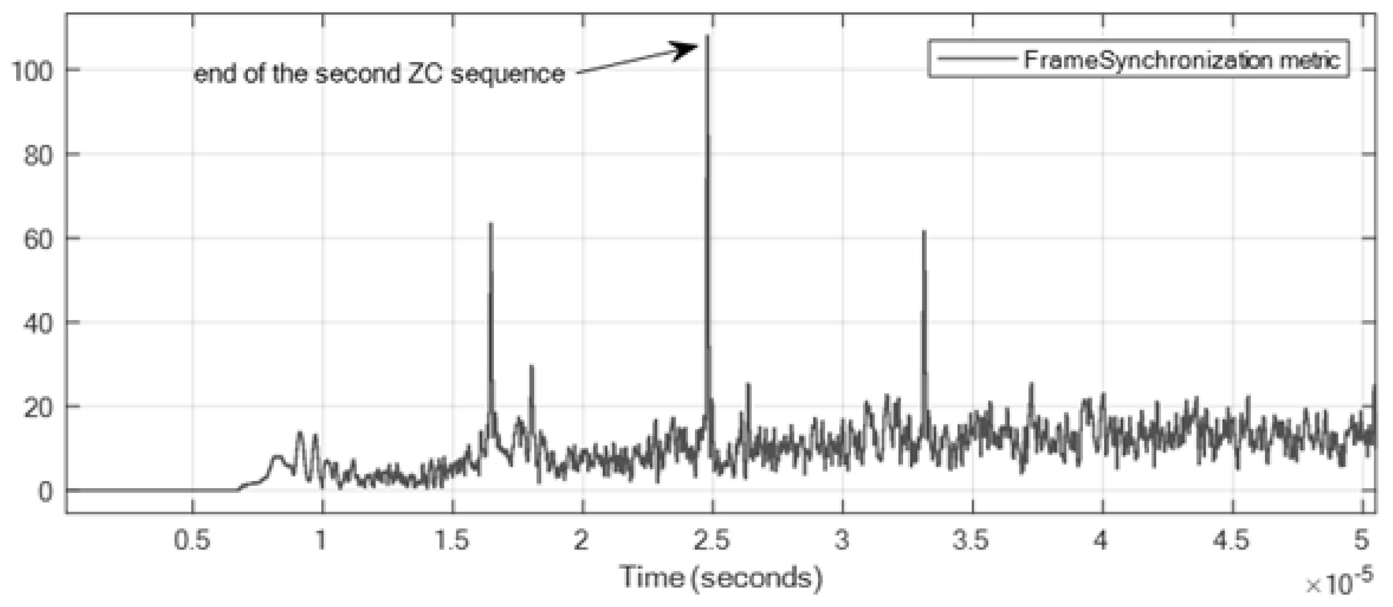
In order to increase the detection capability at the receiver, this extended sequence has been repeated twice in the frame synchronization preamble (T_AMB). Therefore, the correlation metric
is obtained as an average of the results of the cross-correlation of the two sequences with the reference ZC sequence. Finally, the end of the preamble is found as the maximum of the absolute value of
. An example of the time evolution of the metric
while receiving a frame is presented in
Figure 4.
In addition to frame (time) synchronization, the initial CPO can be estimated as the angle of the result of cross-correlation for which the maximum of the metric has been detected.
5.2. Fine Frequency Synchronization
A significant part of the CFO caused by the Doppler shift can be removed with the use of a coarse CFO correction block. However, as the proposed system is intended to operate in the C band, a significant residual CFO might still remain due to the limited capability of tracking of Doppler shift changes. Thus, the purpose of the fine frequency synchronization algorithm is to estimate the impact of such a remaining residual CFO, as well as the mismatch caused by differences in oscillators.
In the proposed feedforward structure a properly designed and sufficiently long (denoted
) frequency synchronization preamble is required, so as to obtain the estimation accuracy close to the theoretical limits of the Cramer–Rao lower bound. For such a purpose we propose a preamble in the form of a complex sinusoidal signal, which can be expressed as
, due to its outstanding robustness to any changes caused, e.g., by transmit or receive filtering. The received signal corresponding to the frequency synchronization preamble
is then demodulated by multiplication with a conjugated sinusoid of the same parameters. with the resulting signal
being a sinusoid with a frequency corresponding to the CFO of the received signal. Thus, CFO estimation is based on finding the frequency of
, which can be realized using the maximum likelihood approach in the form of a periodogram maximizer [
22]. As the calculation of the full periodogram (including averaging) might require too many computations and result in a significant delay, a use of a single discrete Fourier transform (DFT) is considered, with the CFO estimate found as the peak of the DFT of the signal
:
where
is the sampling frequency,
is the DFT size and
is the selected DFT bin index (with the maximum absolute value of
S—the DFT of
s).
The drawback of DFT-based methods is that they are accurate with resolution depending on the DFT size [
21]. To avoid using a very large
, interpolation-based methods are considered to obtain accurate CFO estimates, such as processing of the so-called fractional Fourier coefficients (FFC), as proposed in [
23]. Having found the index
m of the maximum DFT bin, one can use it as an initial estimate of the CFO to calculate the fine estimate using two FFCs. The fine estimate of CFO can be then calculated as:
where
and the FFC is calculated as:
Such an approach can be applied iteratively, with applied as the initial CFO estimate for the calculation of FFCs in the i-th iteration.
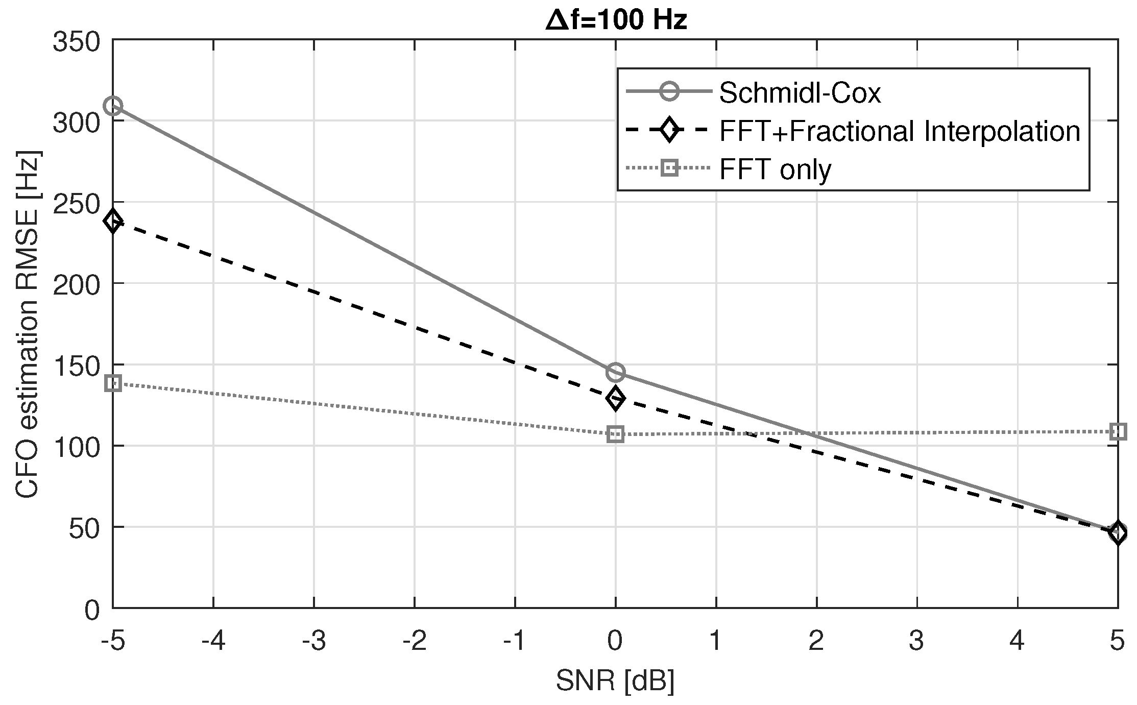
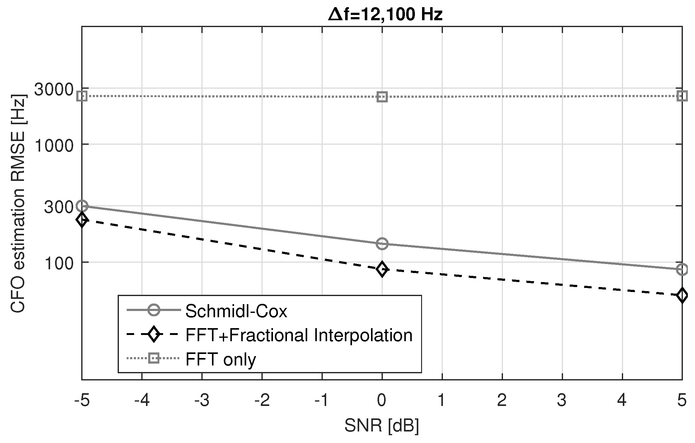
Figure 5 and
Figure 6 present the performance in terms of the observed root mean square error (RMSE) of the CFO estimation achieved with only FFT and FFT with FFC interpolation compared to the well-known Schmidl–Cox algorithm [
24]. Clearly, the highest accuracy is achieved with FFT supported with FFC interpolation.
5.3. Phase Synchronization and Frequency Tracking
The last element of the receiver synchronization system is the phase synchronization and frequency-tracking block that is applied after frame synchronization and compensation for the CFO. Its purpose is to compensate for the remaining small CFO error caused by the variation in the Doppler shift as the satellite changes its position. This procedure uses dedicated short midambles included in the radio frame, interleaved with data blocks, to continuously monitor phase offset changes, and thus to apply corrections to the CFO estimates. This mechanism can be realized in a similar way as in processing of the
preamble. As the mid-section is expected to be short, compared to the data block (a mid-section of the length of 64 symbols is accompanied by a data block of 330 symbols length), an extended ZC sequence, with
and
was used, with eight and nine samples attached to the front and tail, respectively, similarly to (
3). On the receiver side, phase offset tracking is performed using a filter matched to the midamble ZC sequence. The difference in CPO for subsequent midambles is then calculated to find the estimate of the remaining CFO. The phase of the received signal with the CFO of
is given as:
where
is the constant phase offset and
is the noise component. Assuming that the current phase
can be calculated reliably (low impact of variation due to
), one can estimate the CFO based on phase offsets obtained for two samples spaced by
d as follows:
Hence, assuming the noise components cancel out, the remaining CFO can be estimated as:
In order to mitigate the impact of noise components, consecutive estimates are averaged using a simple exponential smoothing filter. An exemplary result of the CFO tracking using the proposed method is shown in
Figure 7.
6. Channel Coding and Link Adaptation
Another important aspect of system design is the selection of the channel coding scheme. The selected approach should, on the one hand, allow us to obtain high performance. On the other hand, only the approaches implementable from the complexity point of view should be considered. Therefore, in this section, the most promising channel coding schemes are briefly presented, and their usefulness for the satellite link is evaluated. Consequently, the discussion is limited to the most promising codes, that is, turbo codes (TC) [
25], low-density parity check (LDPC) [
26], and polar codes (PC) [
27].
The performance comparison of the investigated schemes is presented in
Figure 8 (all investigated schemes have a similar decoding complexity [
28]). As can be seen, the decoding performance of TC and LDPC is quite similar, the difference between these two approaches is ∼0.5 dB at BLER
, which can be neglected in this aplication. The worst performance is observed for the polar codes. Similar remarks can be drawn on the basis of the results presented in, e.g., [
28].
6.1. Encoding Complexity
Since the performance difference between the two best schemes remains within 0.5 dB, the decoding quality cannot be the only criterion used for the selection of the coding scheme. Therefore, in this work, we concentrated on the encoding complexity, since the satellite power consumption should be minimized.
For turbo codes, the encoding process has complexity, where n represents the length of the information message, since the turbo encoder consists of two relatively simple recursive systematic convolutional encoders that perform a low number of bit-wise operations.
In LDPC codes, the generating matrix
, which is transformed from the parity check matrix
, is not as sparse as the parity check matrix. Thus, the complexity of the encoding process is
. However, if the parity matrix
is designed appropriately, the complexity of the encoding can be reduced to
, where
g is the size of one of the submatrices. In the case of
, it can be further simplified to
[
29]. Although the complexity of the TC and LDPC codes can be of the type
, the LDPC encoding process requires more resources.
Based on the above, TC has been selected as the coding scheme for the system under development.
6.2. Link Adaptation
Due to the nature of the satellite link, the achievable SNR is strongly related to the elevation angle. The weakest signal is available for the lowest elevation angles, while the strongest one occurs for 90. Thus, the performance of the system can be optimized by using link adaptation. To cover the operating range of achievable SNR values, a set of seven code rates combined with four channel bandwidths is applied. The procedure is abbreviated as BCS (bandwidth and coding scheme), in analogy to the widely-used MCS (modulation and coding scheme).
The performance of BLER for the set of presumed BCSs is presented in
Figure 9.
However, not all code rate–bandwidth combinations are available; see
Table 4.
The proposed link adaptation procedure is not based on instantaneous link quality (which is typical in, e.g., cellular systems) but on SNR values predicted for a given satellite visibility window over a specific ground station, the recorded history of link throughput, and the BLER, as well as other factors, e.g., weather forecasts. Transmitter settings are planned in advance and signaled to the satellite using a TT&C radio link. For this purpose, a reinforcement learning-based procedure was proposed.
6.3. Machine Learning for Link Adaptation
Using a machine learning (ML) algorithm to predict in advance the optimal bandwidth and code rate for the transmission window offers several distinct advantages over relying solely on a feedback channel. The proactive approach to prediction allows efficient utilization of available resources and reduces the reliance on real-time feedback, which can introduce communication delays and impose additional overhead in a resource-constrained environment.
The development of the machine learning algorithm for link adaptation is carried out in two distinct phases, each serving a specific purpose in optimizing the performance of the communication system for the CubeSat mission. Prior to the satellite launch, the machine learning model is being pre-trained using a supervised learning approach in a simplified simulated environment. The objective of this phase is to provide the model with a foundation of knowledge based on historical records and known scenarios. During pre-training, the model is exposed to a comprehensive data set comprising historical communication session records from similar CubeSat missions. The data set includes essential parameters of the satellites derived from the TLE files, such as elevation and distance to the satellites. A simulated environment is created to represent the expected transmission window. During this phase, two separate models are developed. The first model focuses on predicting the most appropriate bandwidth to be utilized throughout the transmission window. The second model determines the optimal code rate based on the current state of the satellite. To pre-train the models, a brute-force algorithm-based supervisor is employed. This algorithm calculates the optimum bandwidth and code rate for each time instance within the transmission window, using the satellite’s state information extracted from the two-line element (TLE) set file. When considering the elevation, distance, and pointing angle for the entire transmission window with small time increments, the SNR value is calculated for each time instance. Based on SNR values, all possible allowed combinations of bandwidth and code rates are evaluated for each time instance during the entire transmission period. Bandwidth selection is based on achieving the best average throughput throughout the session, while the code rate decision is solely dependent on the SNR value for that specific time and bandwidth. An example calculation can be seen in
Figure 10 for an example trajectory of the satellite AEROCUBE 5C with a timestamp of 24 June 2023 08:31:37–08:39:29 UTC.
The data presented in
Figure 10 provides a comprehensive insight into the relationship between signal-to-noise ratio (SNR) values for different bandwidths and the elevation of the satellite over time. The left axis, which displays the elevation of the satellite, serves as a crucial reference to understand the variations in SNR values throughout the transmission window.
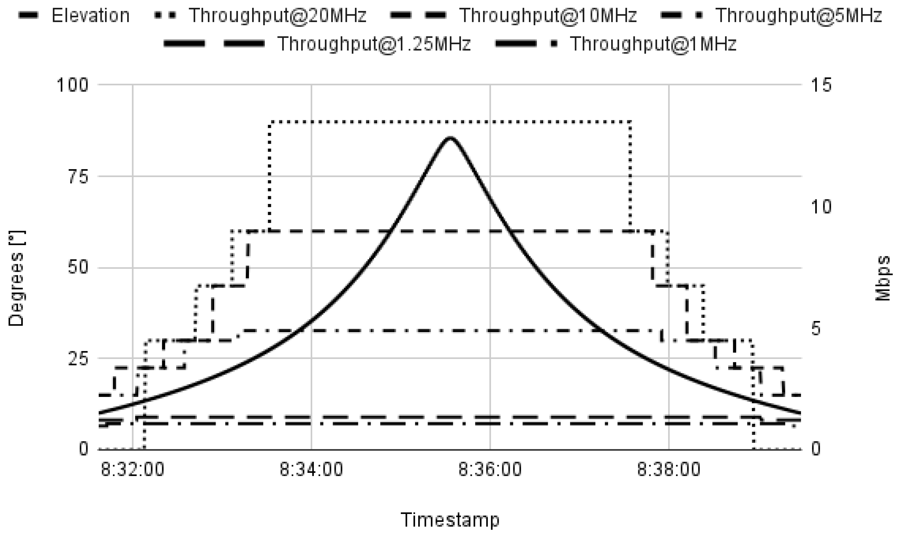
Knowing the SNR value, the brute-force algorithm can then select the best code rate for that specific time instance and calculate the expected theoretical throughput, as seen in
Figure 11. It shows the link adaptation process during the transmission window with the satellite. The x-axis denotes the transmission window time, while the left y-axis indicates the satellite’s elevation, which influences the signal-to-noise ratio (SNR) values. As the SNR values vary with the satellite’s elevation, the right y-axis illustrates how the throughput values for different bandwidths experience sudden changes, resulting from the selection of the optimum code rate based on the prevailing SNR conditions. The bandwidth is chosen based on the highest average throughput for the whole transmission window. The session file for the specific communication window is then created, encompassing crucial details regarding the optimal bandwidth for the entire transmission period and the corresponding optimal code rates for different timestamps within the window. However, despite the brute-force algorithm’s ability to provide the theoretical optimal bandwidth and code rates based on known parameters, it faces limitations in adapting to dynamic changes in the communication environment. The machine learning model is being developed to overcome these limitations and enable reliable link adaptation.
During the pre-training phase, the machine learning model responsible for predicting the code rate interacts with a supervisor that calculates the satellite’s state relative to the ground station. The supervisor then provides the machine learning model with labeled data to facilitate its learning process. The labeled data consist of various inputs, including the distance to the satellite, the elevation angle, the mismatch of the satellite pointing angle, and the bandwidth used during transmission. In particular, the bandwidth provided during pre-training is determined by the brute-force algorithm and not by the bandwidth prediction model. This approach ensures that the model’s training data are accurate and free from any uncertainties that may arise from using predictions in the early stages. The desired output provided by the machine learning model is the signal-to-noise ratio (SNR) value. The selection of SNR as the output is a purely arbitrary choice for now, and the model structure might change later on if another model will have more potential. By focusing on predicting the SNR value, the model aims to offer a continuous measure of communication quality, which streamlines the decision-making process for code rate selection. Once the first model predicts the most suitable bandwidth for the transmission window and the second model provides the SNR value for the current state of the satellite, the best code rate can be determined programmatically through a lookup table. Choosing an appropriate model structure is a time-consuming process that involves extensive testing and validation, and therefore, potentially can be subject to change. One of the key challenges is to strike the right balance of the structural complexity of the model. An overly complex model may lead to overfitting, where the model performs exceptionally well on the training data, but struggles to generalize to new, unseen data. On the other hand, an overly simplistic model can result in underfitting, where the model fails to capture the underlying patterns in the data, leading to suboptimal performance [
30]. However, to demonstrate the results of the current state of the pre-training state, the model with five layers was chosen for the prediction of the SNR value. The input layer contains four nodes, the hidden layers consist of 8 × 16 × 8 nodes, and one node at the output layer (4 × 8 × 16 × 8 × 1). Four inputs have been discussed above: distance to the satellite (km), elevation of the satellite (
), mismatch of the satellite pointing angle (
), and chosen bandwidth (MHz). The output node provides a floating-number prediction of the SNR value (dB) based on the input. After training the example model for 1000 epochs over 50,000 samples in each epoch, we can evaluate the results on an unseen set of data for the model, which was taken from a satellite AEROCUBE 6A with a timestamp of 17 July 2023 03:24:18–03:37:29 UTC, as seen in
Figure 12. It presents a comparison of the signal-to-noise ratio (SNR) values for a bandwidth of 20 MHz derived from both the brute-force algorithm and the machine learning model throughout the transmission window with the satellite. The x-axis represents the transmission window time, while the left y-axis displays the satellite elevation, which significantly influences the SNR values. The right y-axis shows the comparison of the SNR values obtained from the two methods. The evaluation of the machine learning model demonstrates promising performance, with results following a similar trend to the brute-force algorithm. Although the model underpredicts the values by an average of 0.4 dB, it is important to note that this level of accuracy was achieved within a relatively short training period with limited training data. Unlike the brute-force algorithm, which relies solely on known parameters and lacks adaptability, the machine learning model exhibits the potential for further improvement.
After the pre-training phase, the model will transition to the fine-tuning phase, where reinforcement learning (RL) will be employed. In this phase, the model will be introduced to the real-world environment, allowing it to interact with the actual communication sessions and receive feedback in the form of rewards or penalties based on its actions [
31]. The reward function will be defined to maximize throughput while minimizing the frame error rate (FER). During the fine-tuning phase, the model will also utilize additional data gathered from the real-world environment, such as actual throughput and FER values, as well as real-time weather conditions and other real-time imperfections and phenomena. This rich data set allows the model to calibrate its decision-making process and refine its link adaptation strategies to cope with dynamic channel conditions and environmental variations. By combining pre-training knowledge with real-world interactions and reinforcement learning, the machine learning algorithm will be equipped to make intelligent and informed link adaptation decisions, ensuring optimal communication performance throughout the CubeSat mission. The efficiency of the communication is expected to be higher than by utilizing the pure calculations approach, as RL will be able to adapt to the dynamic conditions. However, this can be confirmed only by extensive simulations and/or measurements in the real world, which are planned for the next phase of the project.
7. System Implementation
The transmitter was developed as a custom-built module in PC/104 format, popular in Cubesat satellite platforms. Baseband processing was implemented using the Xilinx Zynq Z7030 SoC (San Jose, CA, USA), with physical layer algorithms running on FPGA and higher-layer procedures running on ARM cores. The I/Q samples were transferred to the Analog Devices AD9364 integrated transceiver (Wilmington, MA, USA), delivering the RF signal in the 5.8 GHz band. The output stage was based on an Analog Devices HMC7357 2 W GaAs power amplifier. The module consumes less than 15 W when transmitting CW at maximum gain. The transmitter uses a 2× 2 circular polarized patch antenna.
Two versions of the ground station receiver were developed for system flexibility. The online mode of system operation uses the SDR receiver based on the high-performance Zynq Z7100 SoC (Xilinx, San Jose, CA, USA), featuring 3.5×more LUTs comparing to Z7030, and the AD9364-integrated transceiver. The platform was implemented using off-the-shelf development modules, i.e., mini-ITX from Avnet (Phoenix, AZ, USA) and FMCOMMS3 from Analog Devices. The offline mode of operation uses a low-cost receiver, with all signal processing running on a PC and a USRP B200/B210 SDR module from National Instruments (Austin, TX, USA) acting as an RF front-end. The software receiver was implemented using the GnuRadio 3.10.2.0. platform and custom (OOT) blocks. At the ground station, a 3 m tracking parabolic antenna with a custom-made septum feed and a 28 dB gain LNA is installed.
In the first phase the developed system was tested in the laboratory and it passed all functional tests. The measurements showed that the transmitter module is able to deliver +32 dBm at a 50 Ohm load with EVM < 5% (RMS value). Performance (FER/BER vs. SNR) field tests (terrestrial), in line-of-sight conditions on a 10 km transmitter-to-receiver distance will be carried out in the second phase. The phase will be completed before forwarding the transmitter module to the system integrator and environmental tests of the satellite.
8. Conclusions and Future Work
We have developed a CubeSat broadband communication system operating in the C band. This is particularly relevant in view of the continuously increasing number of CubeSat systems operating in the limited spectrum used so far.
Compared to commercially-available solutions, the system is less expensive, while still delivering reasonable performance. A fully operational version will be installed onboard satellites and tested in orbit in 2024. However, the system still needs extensive testing before the satellites will be launched.
Currently, there is still limited availability of ground stations operating at 5.8 GHz. None of the popular ground station networks, e.g., Atlas, RBC Signals, AWS, and SatNOGS, operate in the C band. However, we believe that the low cost of both the C-band ground station and the satellite module developed as part of the project will encourage many parties to use it in their applications, and the number of ground stations will increase in the coming years.
Author Contributions
Conceptualization, R.K. and K.W.; methodology, K.W., P.S., M.S. and I.Z.; software, K.W., P.S., M.S. and I.Z.; validation, R.K; formal analysis, K.W., P.S., M.S. and I.Z.; investigation, K.W., P.S., M.S. and I.Z.; resources, R.K.; data curation, R.K.; writing—original draft preparation, R.K., K.W., P.S., M.S. and I.Z.; writing—review and editing, K.W. and R.K.; visualization, K.W. and R.K.; supervision, R.K.; project administration, R.K.; funding acquisition, R.K. All authors have read and agreed to the published version of the manuscript.
Funding
This work was supported by the National Center for Research and Development under Grant No. POIR.01.01.01-00-1211/19-00 and by the Ministry of Education and Science under 0312/SBAD/8163 project.
Data Availability Statement
Since the system operates in an amateur band, full system specifications, as well as the receiver software, are publicly available on the project Web site at
http://pw6u.put.poznan.pl (accessed on 29 September 2023).
Acknowledgments
The authors wish to thank the other members of the team: Maciej Krasicki, Tomasz G. Markiewicz, Marek Michalski, and Marcin Rodziewicz who were involved in the system design and development.
Conflicts of Interest
The authors declare no conflict of interest.
Abbreviations
The following abbreviations are used in this manuscript:
| BCS | Bandwidth and Coding Scheme |
| BER | Bit Error Rate |
| BLER | Block Error Rate |
| BPSK | Binary Phase Shift Keying |
| CCSDS | Consultative Committee for Space Data Systems |
| CFO | Carrier Frequency Offset |
| CPO | Carrier Phase Offset |
| DA | Data-Aided |
| DC | Direct Current |
| DFT | Discrete Fourier Transform |
| DVB-S2 | Digital Video Broadcasting—Satellite Second Generation |
| EDGE | Enhanced Data rate for Global Evolution |
| FFC | Fractional Fourier Coefficients |
| FFT | Fast Fourier Transform |
| GMSK | Gaussian Minimum Shift Keying |
| ISI | Inter-Symbol Interference |
| ITU | International Telecommunication Union |
| KPI | Kyiv Polytechnic Institute |
| LEO | Low Earth Orbit |
| LDPC | Low Density Parity Check |
| LLR | Log-Likelihood Ratio |
| MCS | Modulation and Coding Scheme |
| ML | Machine Learning |
| NORAD | North American Aerospace Defense Command |
| OQPSK | Offset Quadrature Phase Modulation |
| PAPR | Peak-to-Average Power Ratio |
| PC | Polar Codes |
| PSD | Power Spectral Density |
| PUT | Poznan University of Technology |
| RF | Radio Frequency |
| RMSE | Root Mean Square Error |
| SDR | Software Defined Radio |
| SNR | Signal-to-Noise Ratio |
| TC | Turbo Code |
| TLE | Two-Line Elements |
| TT&C | Tracking, Telemetry and Control |
| UHF | Ultra High Frequency |
| USRP | Universal Software Radio Peripheral |
| VHF | Very High Frequency |
| ZC | Zadoff–Chu |
References
- Amateur and Amateur-Satellite Service Spectrum; Administrative Council International Amateur Radio Union: Newington, CT, USA, 2020.
- Devarajy, K.; Ligon, M.; Blossom, E.; Breu, J.; Klofas, B.; Colton, K.; Kingsbury, R. Planet High Speed Radio: Crossing Gbps from a 3U Cubesat. In Proceedings of the 33rd Annual AIAA/USU Conference on Small Satellites, Utah State University, Logan, UT, USA, 3–8 August 2019; pp. 1–10. [Google Scholar]
- Syrinks. Available online: https://www.syrlinks.com/en/space/nano-satellite/x-band-transmitter-ewc27 (accessed on 29 September 2023).
- Endurosat. Available online: https://www.endurosat.com/cubesat-store/cubesat-communication-modules/x-band-transmitter/ (accessed on 29 September 2023).
- Satlab. Available online: https://www.satlab.com/products/srs-3/ (accessed on 29 September 2023).
- ISISPACE. Available online: https://www.isispace.nl/product/isis-txs-s-band-transmitter/ (accessed on 29 September 2023).
- Francis, C.L. ISM S-Band Cubesat Radio Designed for the Polysat System Board. Master’s Thesis, California Polytechnic State University, San Luis Obispo, CA, USA, 2016. [Google Scholar]
- Subirana, M.P. High Speed S-Band Communications System for Nanosatellites. Master’s Thesis, Universitat Politecnica de Catalunya, Barcelona, Spain, 2016. [Google Scholar]
- Juarez-Ortizand, V.A.; Perea-Tamayo, R. Design of a C-band high gain microstrip antenna array for CubeSat standard. In Proceedings of the IEEE MTT-S Latin America Microwave Conference, Arequipa, Peru, 12–14 December 2018; pp. 1–3. [Google Scholar]
- AMSAT-UK. Spreadsheet Calculators. 2013. Available online: http://www.amsat.org/wordpress/xtra/AMSAT-IARU_Link_Model_Rev2.5.3.xls (accessed on 29 September 2023).
- The Consultative Committee for Space Data Systems. Bandwidth-Efficient Modulations—Summary of Definition, Implementation and Performance; Informational Report CCSDS 413.0-G-3, Green Book; NASA: Washington, DC, USA, 2018. [Google Scholar]
- The Consultative Committee for Space Data Systems. Radio Frequency and Modulation Systems—Part 1, Earth Stations and Spacecraft; Recommended Standard CCSDS 401.0-B-31, Blue Book; NASA: Washington, DC, USA, 2021. [Google Scholar]
- Laurent, P.A. Exact and approximate construction of digital phase modulations by superposition of amplitude modulated pulses. IEEE Trans. Commun. 1986, 2, 150–160. [Google Scholar] [CrossRef]
- Lui, G.L. Threshold detection performance of GMSK signal with BT = 0.5. In Proceedings of the IEEE Military Communication Conference (MILCOM), Boston, MA, USA, 19–21 October 1998; pp. 515–519. [Google Scholar]
- Ungerboeck, G. Adaptive maximum-likelihood receiver for carrier-modulated data-transmission systems. IEEE Trans. Commun. 1974, 5, 624–636. [Google Scholar] [CrossRef]
- Hagenauer, J.; Hoeher, P. A Viterbi algorithm with soft-decision outputs and its applications. In Proceedings of the IEEE Global Communications Conference (GLOBECOM), Dallas, TX, USA, 27–30 November 1989; pp. 1680–1686. [Google Scholar]
- Yakhnich, E.; Reshef, E. Soft Decision Output Generator. U.S. Patent 6,731,700 B1, 4 May 2004. [Google Scholar]
- Wesołowski, K. Introduction to Digital Communication Systems; John Wiley & Sons: Chichester, UK, 2009. [Google Scholar]
- Rouzegar, H.; Ghanbarisabagh, M. Estimation of Doppler curve for LEO satellites. Wirel. Pers. Commun. 2019, 108, 2195–2212. [Google Scholar] [CrossRef]
- Amiri, S.; Mehdipour, M. Accurate Doppler frequency shift estimation for any satellite orbit. In Proceedings of the 2007 3rd International Conference on Recent Advances in Space Technologies, Istanbul, Turkey, 14–16 June 2007; pp. 602–607. [Google Scholar]
- Gul, M.M.U.; Ma, X.; Lee, S. Timing and frequency synchronization for OFDM downlink transmissions using Zadoff-Chu sequences. IEEE Trans. Wirel. Commun. 2015, 3, 1716–1729. [Google Scholar] [CrossRef]
- Hosseini, E.; Perrins, E. Timing, carrier and frame synchronization of burst-mode CPM. IEEE Trans. Commun. 2011, 12, 5125–5138. [Google Scholar] [CrossRef]
- Aboutanios, E. Frequency Estimation for Low Earth Orbit Satellites. Ph.D. Thesis, University of Technology, Sydney, Australia, 2002. [Google Scholar]
- Schmidl, T.M.; Cox, D.C. Robust frequency and timing synchronization for OFDM. IEEE Trans. Commun. 1997, 12, 1613–1621. [Google Scholar] [CrossRef]
- Berrou, C.; Glavieux, A.; Thitimajshima, P. Near Shannon limit error-correcting coding and decoding: Turbo-codes. (1). In Proceedings of the IEEE International Conference on Communications (ICC), Geneva, Switzerland, 23–26 May 1993; pp. 1064–1070. [Google Scholar]
- Richardson, T.J.; Shokrollahi, M.A.; Urbanke, R.L. Design of capacity-approaching irregular low-density parity-check codes. IEEE Trans. Inform. Theory 2001, 2, 619–637. [Google Scholar] [CrossRef]
- Arikan, E. Channel polarization: A method for constructing capacity-achieving codes for symmetric binary-input memoryless channels. IEEE Trans. Inform. Theory 2009, 7, 3051–3073. [Google Scholar] [CrossRef]
- Sybis, M.; Wesołowski, K.; Jayasinghe, K.; Venkatasubramanian, V.; Vukadinovic, V. Channel coding for ultra-reliable low-latency communication in 5G systems. In Proceedings of the 2016 IEEE 84th Vehicular Technology Conference (VTC), Montréal, QC, Canada, 18–21 September 2016; pp. 1–5. [Google Scholar]
- Fossorier, M.P.C. Quasicyclic low-density parity-check codes from circulant permutation matrices. IEEE Trans. Inform. Theory 2004, 8, 1788–1793. [Google Scholar] [CrossRef]
- Burkov, A. The Hundred-Page Machine Learning Book; Andryi Burkov: Quebec City, QC, Canada, 2019; pp. 58–62. [Google Scholar]
- Suttonand, R.S.; Barto, A.G. Reinforcement Learning: An Introduction, 2nd ed.; The MIT Press: Cambridge, MA, USA, 2018; pp. 53–55. [Google Scholar]
Figure 1.
The calculated values of signal-to-noise ratios for a broadband CubeSat communication system.
Figure 1.
The calculated values of signal-to-noise ratios for a broadband CubeSat communication system.
Figure 4.
Example of an observed frame (time) synchronization metric evolution for SNR = 0 dB—the highest peak denotes the end of the second Zadoff–Chu sequence (start of frequency synchronization preamble offset by a known number of samples).
Figure 4.
Example of an observed frame (time) synchronization metric evolution for SNR = 0 dB—the highest peak denotes the end of the second Zadoff–Chu sequence (start of frequency synchronization preamble offset by a known number of samples).
Figure 5.
Comparison of the RMSE of different CFO estimation methods for 20 MHz bandwidth, preamble length symbols and Hz.
Figure 5.
Comparison of the RMSE of different CFO estimation methods for 20 MHz bandwidth, preamble length symbols and Hz.
Figure 6.
Comparison of RMSE values of different CFO estimation methods for 20 MHz bandwidth, preamble length symbols, and 12,100 Hz.
Figure 6.
Comparison of RMSE values of different CFO estimation methods for 20 MHz bandwidth, preamble length symbols, and 12,100 Hz.
Figure 7.
Example of CFO tracking for system bandwidth of 1.25 MHz, SNR = 5 dB, and the smoothing filter factor .
Figure 7.
Example of CFO tracking for system bandwidth of 1.25 MHz, SNR = 5 dB, and the smoothing filter factor .
Figure 8.
BLER performance comparison for , , QPSK.
Figure 8.
BLER performance comparison for , , QPSK.
Figure 9.
BLER performance of different MCSs, turbo code.
Figure 9.
BLER performance of different MCSs, turbo code.
Figure 10.
SNR values for different bandwidth selections with reference to the elevation of the satellite.
Figure 10.
SNR values for different bandwidth selections with reference to the elevation of the satellite.
Figure 11.
Theoretical throughput at different bandwidths with reference to the elevation of the satellite.
Figure 11.
Theoretical throughput at different bandwidths with reference to the elevation of the satellite.
Figure 12.
Comparison of the results between a brute-force algorithm and machine learning model for 20 MHz bandwidth with reference to the elevation of the satellite.
Figure 12.
Comparison of the results between a brute-force algorithm and machine learning model for 20 MHz bandwidth with reference to the elevation of the satellite.
Table 1.
Requirements for the communication subsystem.
Table 1.
Requirements for the communication subsystem.
| Parameter | Value |
|---|
| Min. net user throughput | 10 Mbps |
| Packet error rate | < |
| Max. transmit power | 33 dBm (2 W) |
| Operating frequency | 5830–5850 MHz |
| Selectable signal bandwidth | 1.25–20 MHz |
| Immunity to Doppler shift | ≥ kHz |
Table 2.
Achievable data rates (Mbps) for different channel bandwidths and values of and PAPR values for linearized GMSK modulation.
Table 2.
Achievable data rates (Mbps) for different channel bandwidths and values of and PAPR values for linearized GMSK modulation.
| | BT = 0.2 | BT = 0.25 | BT = 0.3 | BT = 0.35 |
|---|
| F | 0.56 | 0.62 | 0.65 | 0.67 |
| W = 1.25 MHz | 1.12 | 1.01 | 1.01 | 0.93 |
| W = 5 MHz | 4.46 | 4.03 | 3.85 | 3.73 |
| W = 10 MHz | 8.93 | 8.06 | 7.69 | 7.46 |
| W = 20 MHz | 17.86 | 16.13 | 15.38 | 14.93 |
| PAPR (dB) | 1.20 | 0.73 | 0.55 | 0.41 |
Table 3.
Data rates (Mbps) and PAPR values for several roll-off factors of square-root raised cosine transmit filter for OQPSK modulation.
Table 3.
Data rates (Mbps) and PAPR values for several roll-off factors of square-root raised cosine transmit filter for OQPSK modulation.
| | | | | |
|---|
| F | 0.60 | 0.63 | 0.65 | 0.67 |
| W = 1.25 MHz | 2,08 | 1.98 | 1.92 | 1.87 |
| W = 5 MHz | 8.33 | 7.94 | 7.69 | 7.46 |
| W = 10 MHz | 16.67 | 15.87 | 15.38 | 14.93 |
| W = 20 MHz | 33.33 | 31.74 | 30.77 | 29.85 |
| PAPR (dB) | 4.0 | 3.76 | 3.52 | 3.28 |
Table 4.
Available code rate–bandwidth combinations.
Table 4.
Available code rate–bandwidth combinations.
| | 20 MHz | 10 MHz | 5 MHz | 1.25 MHz |
|---|
| | | | x |
| | | x | x |
| | x | x | x |
| x | x | x | x |
| x | x | x | x |
| x | x | x | x |
| x | x | x | x |
| Disclaimer/Publisher’s Note: The statements, opinions and data contained in all publications are solely those of the individual author(s) and contributor(s) and not of MDPI and/or the editor(s). MDPI and/or the editor(s) disclaim responsibility for any injury to people or property resulting from any ideas, methods, instructions or products referred to in the content. |
© 2023 by the authors. Licensee MDPI, Basel, Switzerland. This article is an open access article distributed under the terms and conditions of the Creative Commons Attribution (CC BY) license (https://creativecommons.org/licenses/by/4.0/).


