
Research on Sliding Mode Control of Dual Active Bridge Converter Based on Linear Extended State Observer in Distributed Electric Propulsion System


Abstract
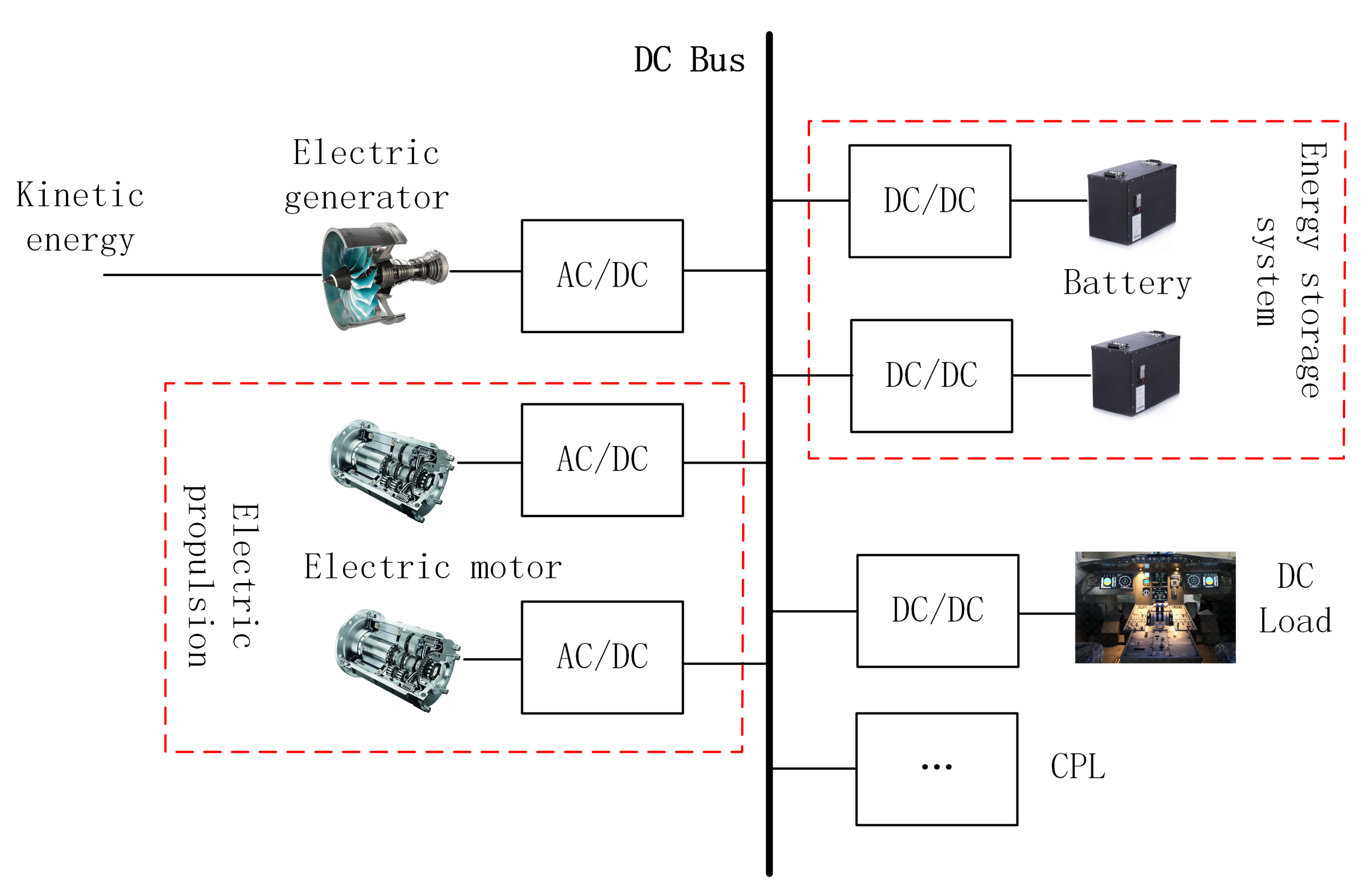
:1. Introduction
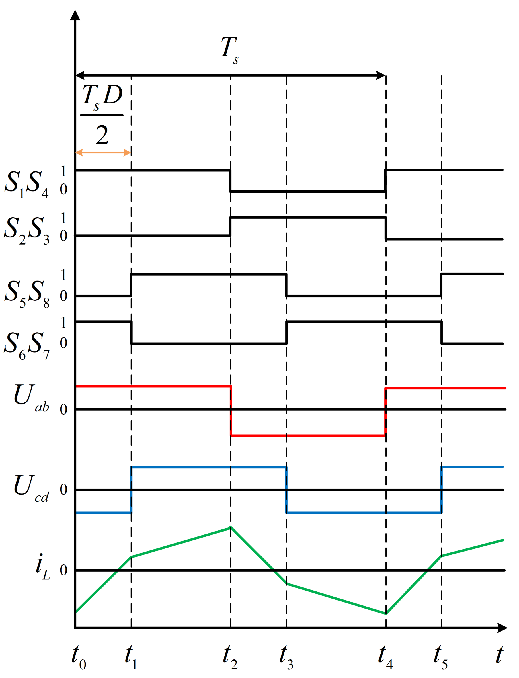
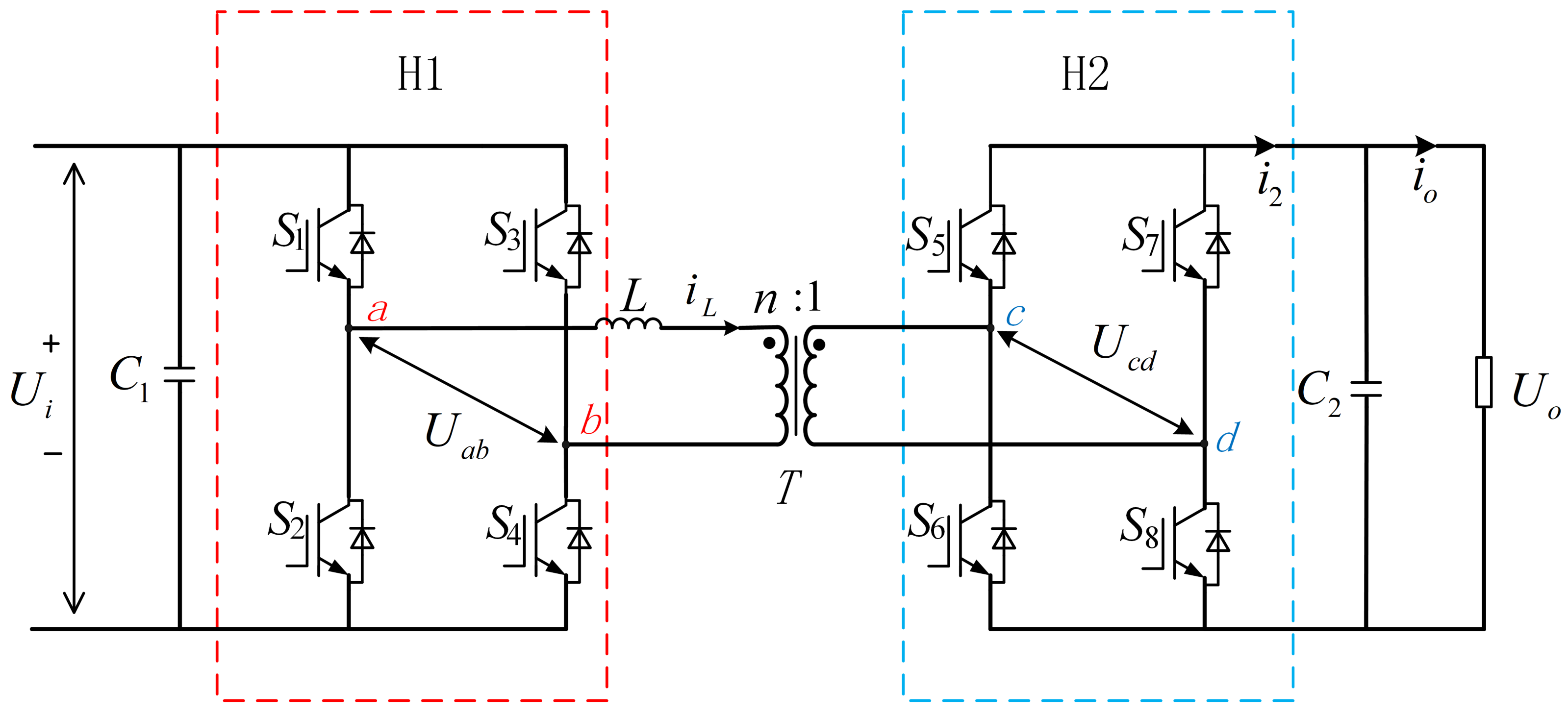
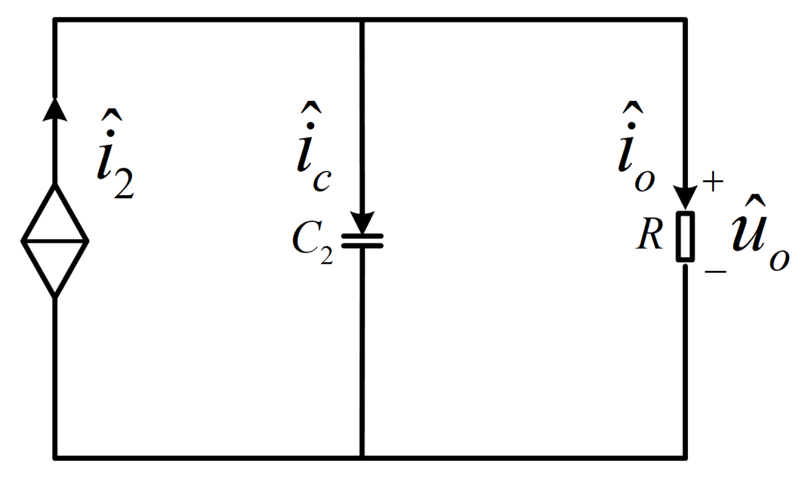
2. Analysis of the Working Principle of DAB Converter
3. Controller Design of DAB Converter
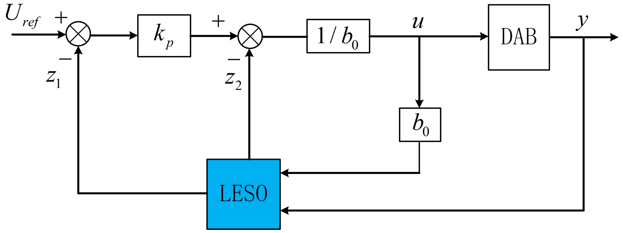
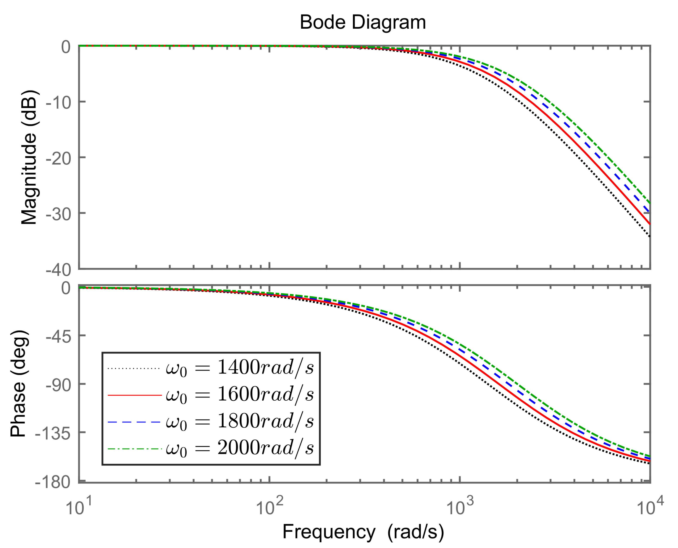
3.1. Design of Linear Active Disturbance Rejection Control
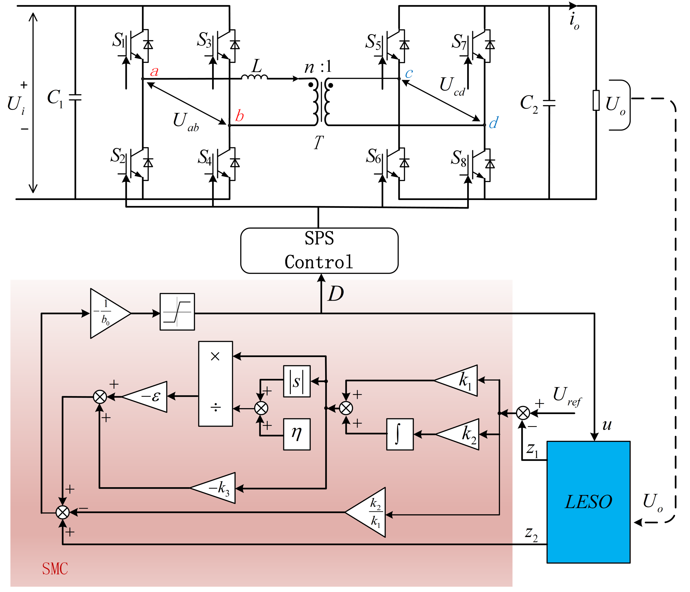
3.2. Design of Sliding Mode Control Based on Linear Extended State Observer
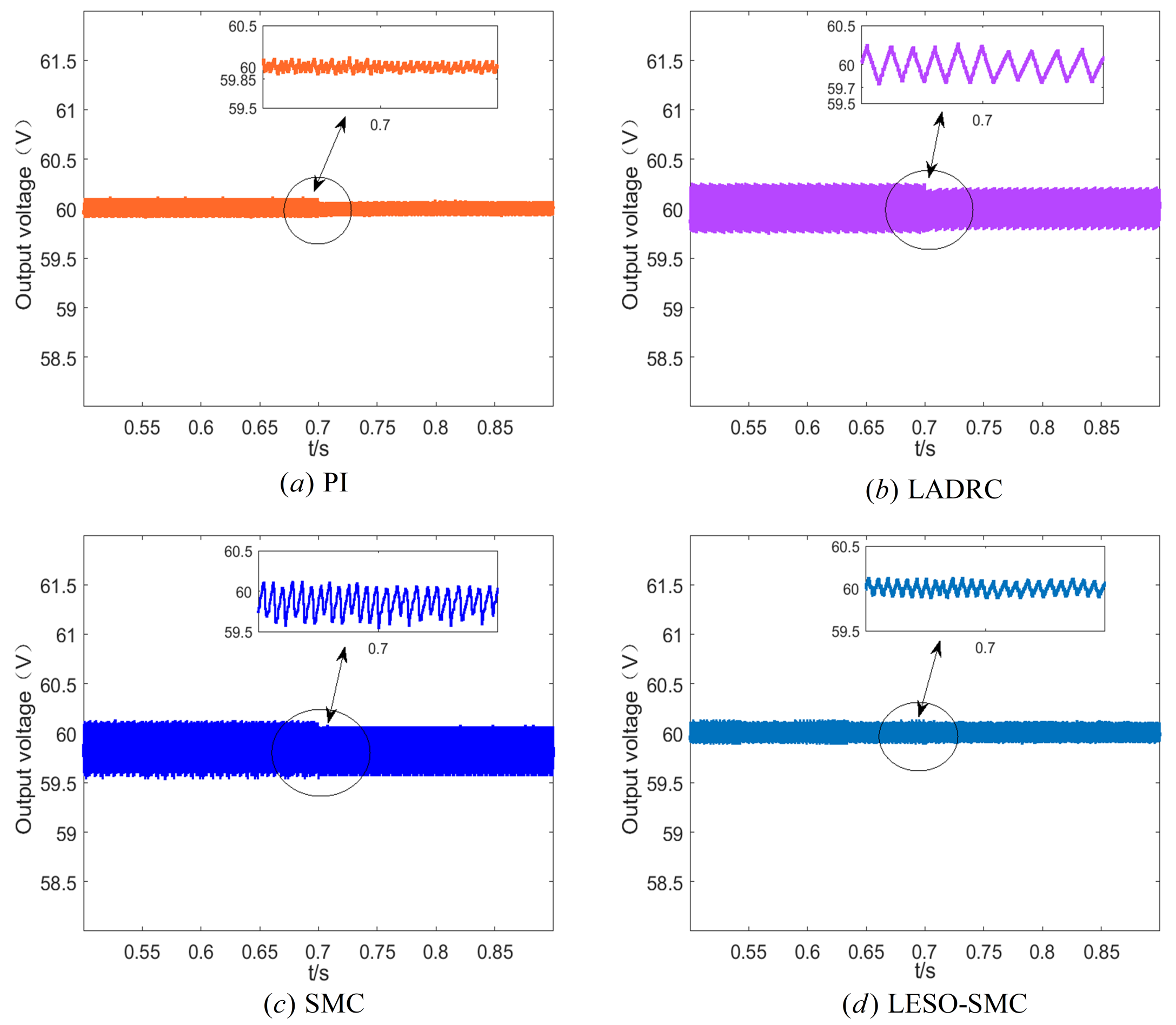
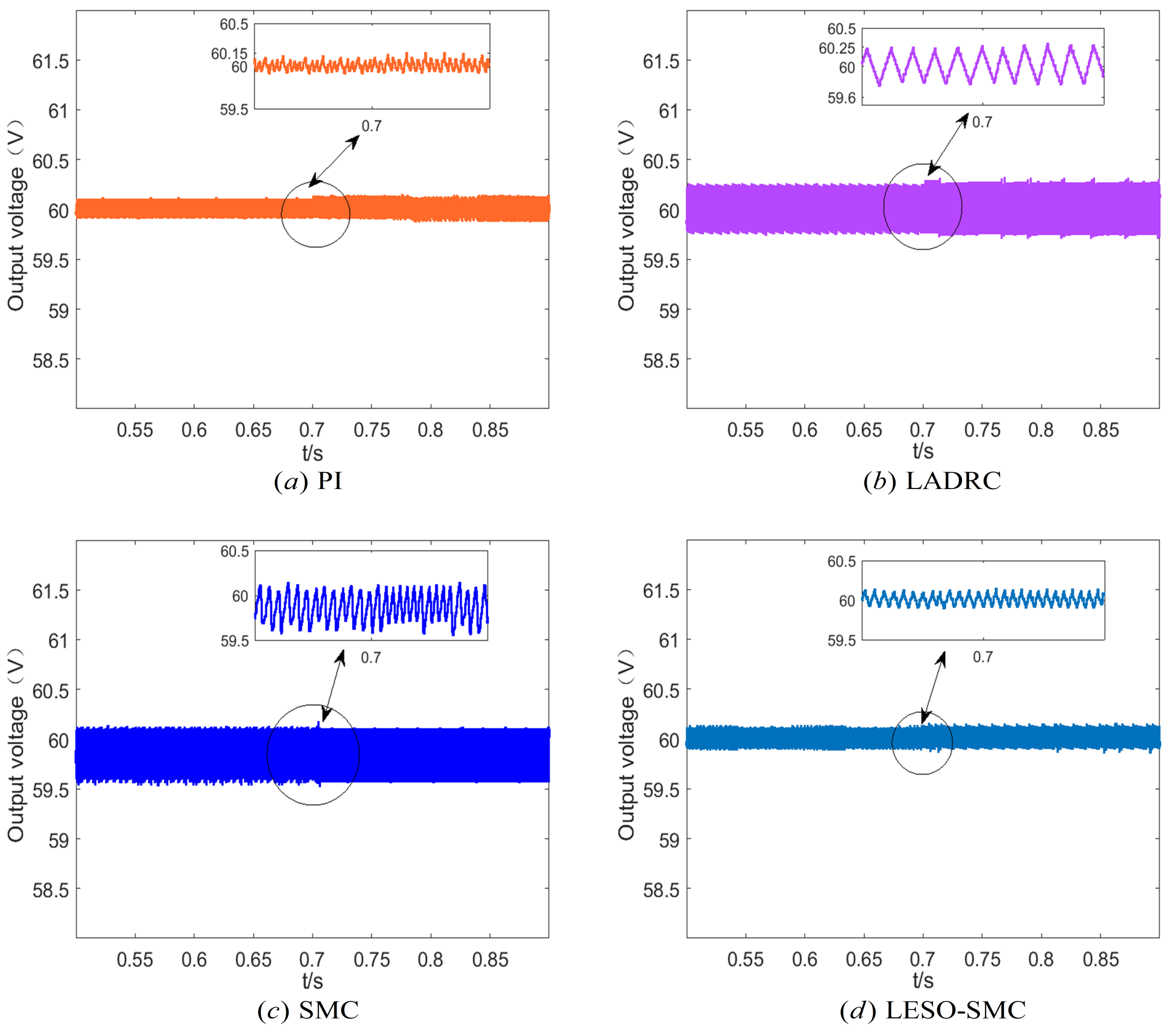
4. Analysis of Simulation Experiment Results
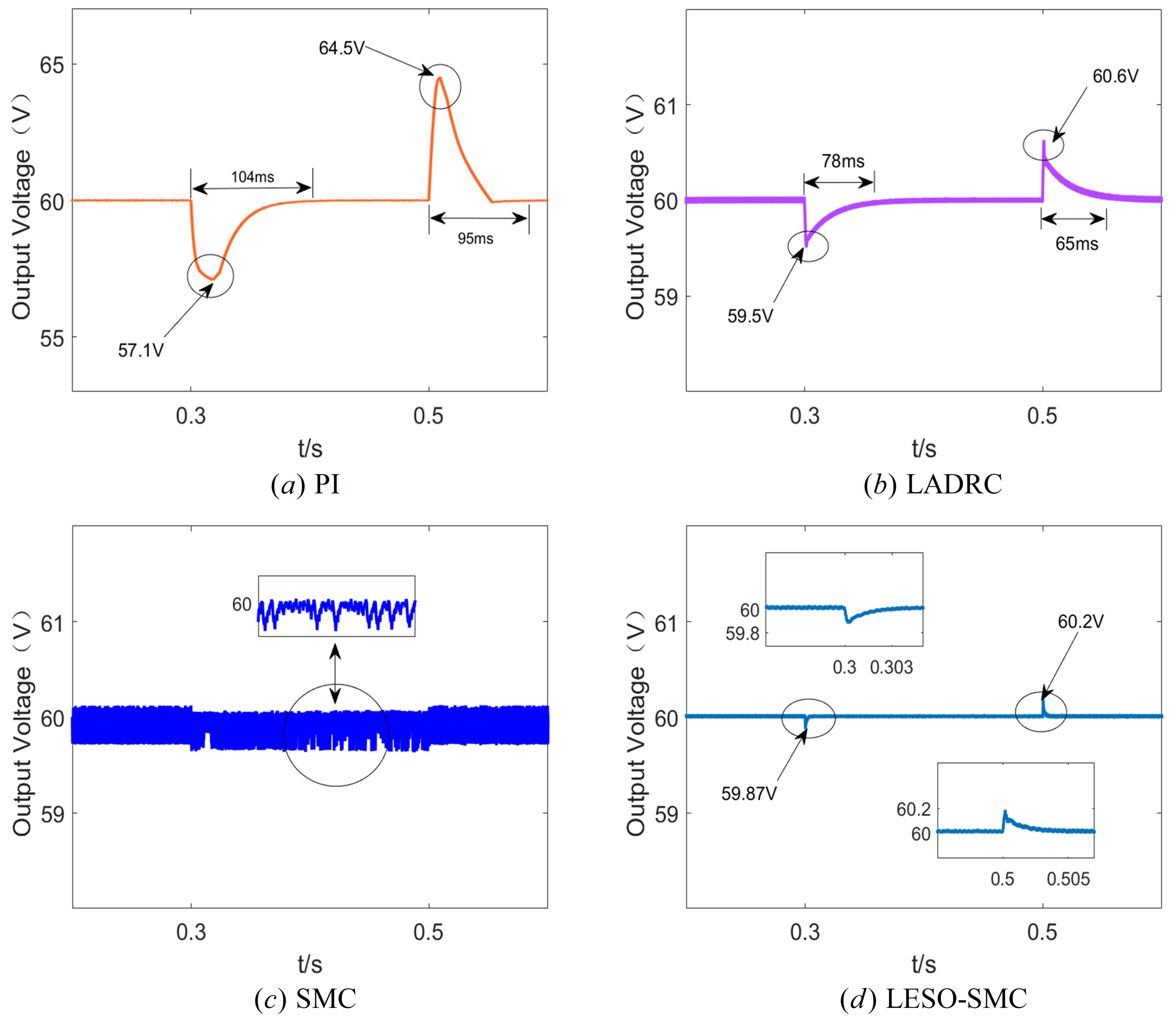
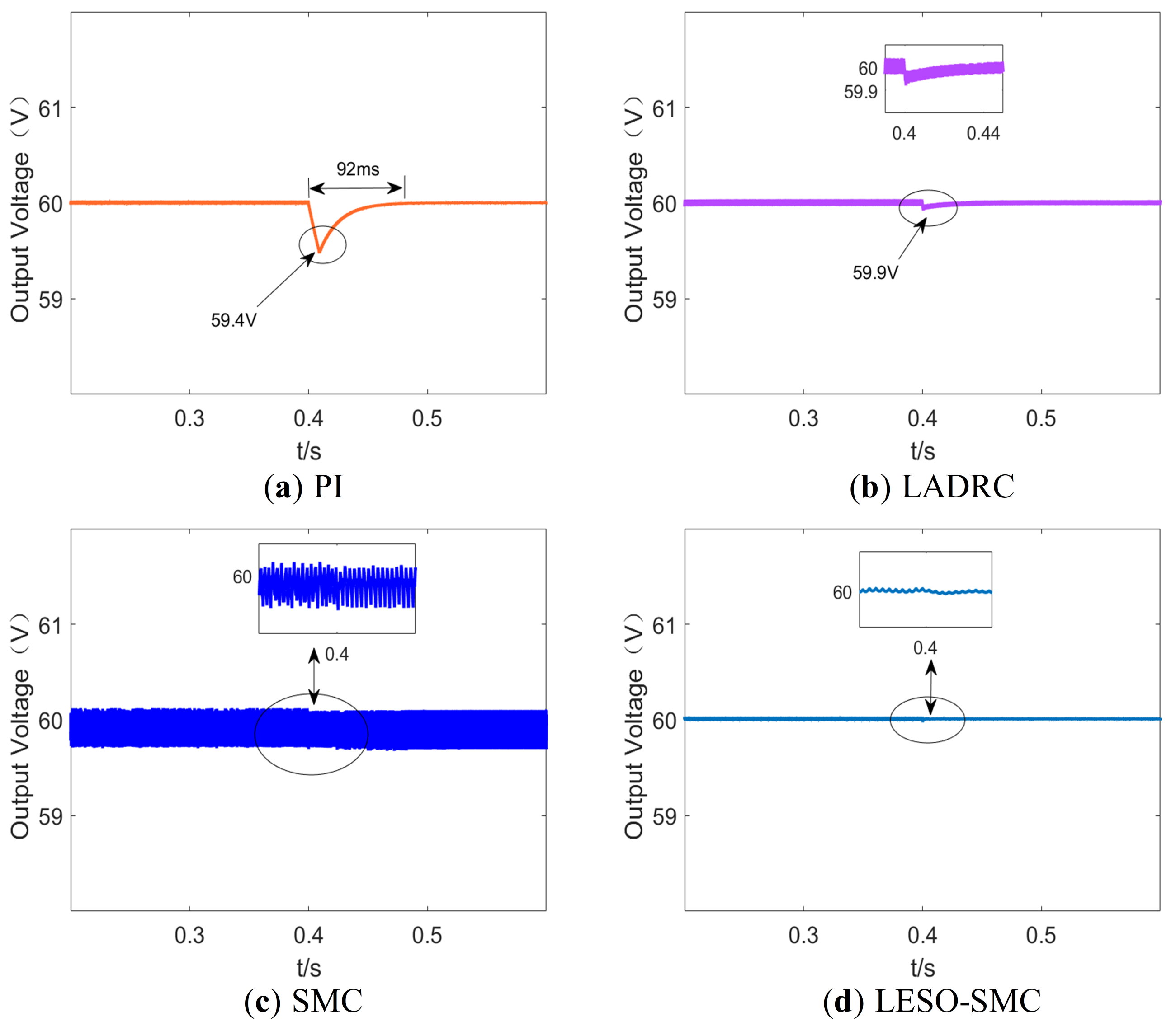
4.1. Load Change Experiment
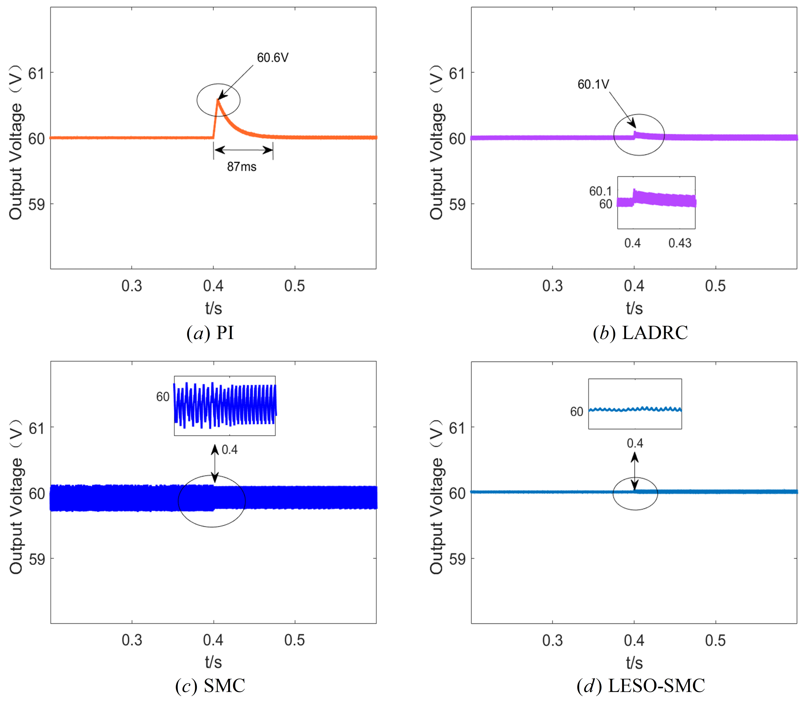
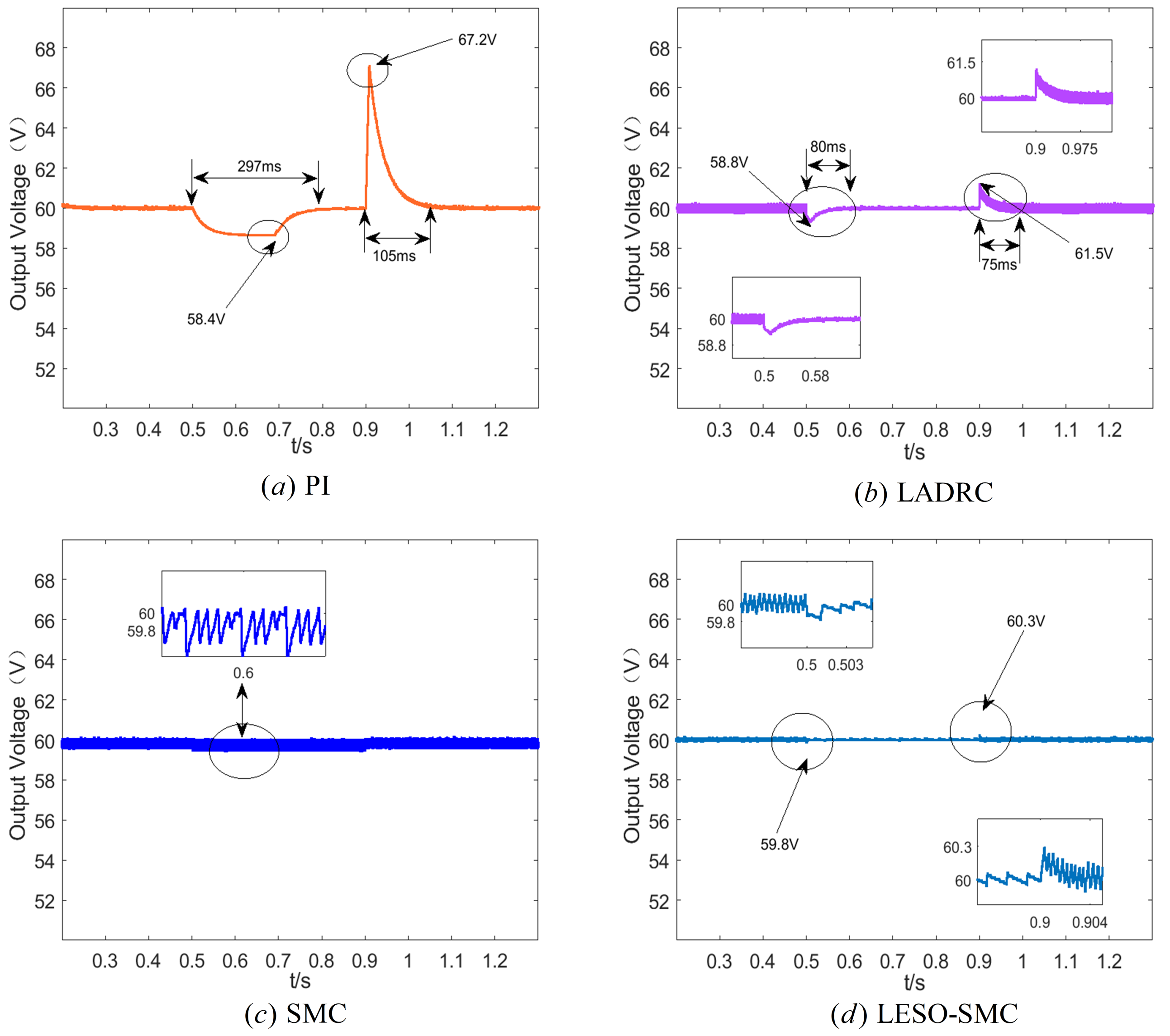
4.2. Input Voltage Change Experiment
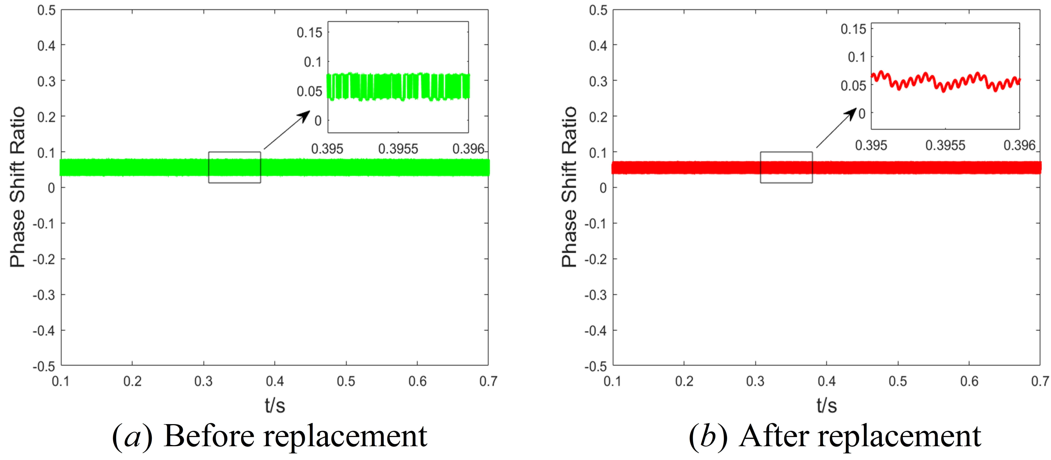
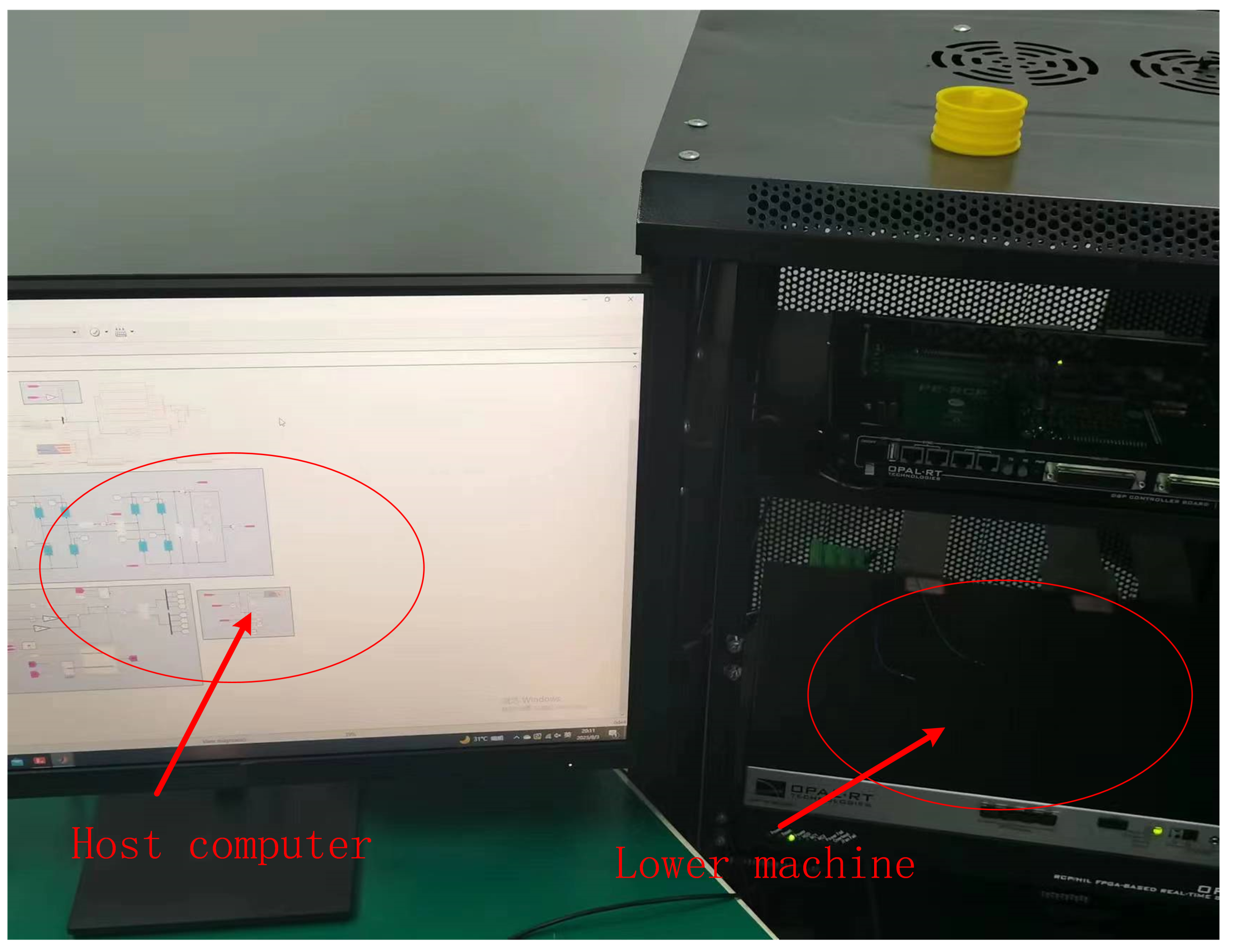
4.3. Semi-Physical Experimental Verification
5. Conclusions
- (1)
- Firstly, the principle of SPS control is elaborated in detail, and the reduced order dynamic model is derived. Then, based on this model, the LADRC strategy is designed, and the ability of the LESO to compensate for the system disturbance is used to improve the anti-interference ability and dynamic performance of the converter.
- (2)
- In order to further improve the performance of the converter, the LESO is combined with SMC, and the nonlinear error feedback law constructed by the observer’s value and the switching function can better adapt to the nonlinear characteristics of the converter, which is no serious chattering phenomenon.
- (3)
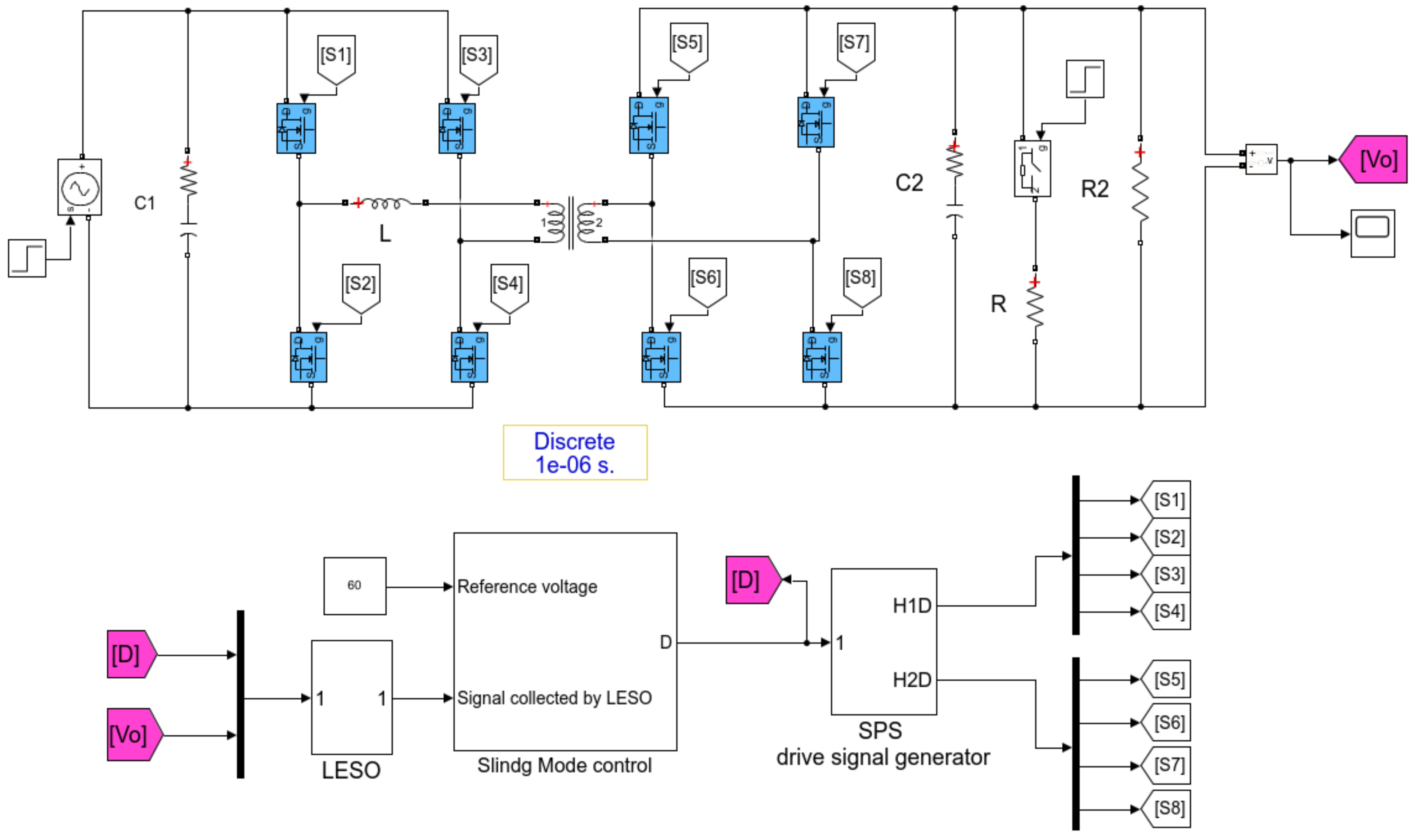
- Finally, the strategy is verified on the Matlab/Simulink and RT-Lab platform. The theoretical and experimental results show that the LESO-SMC strategy proposed in this paper has stronger robustness and better dynamic performance under the conditions of load mutation and input voltage change and can achieve a stable tracking of the output reference voltage.
Author Contributions
Funding
Data Availability Statement
Conflicts of Interest
References
- Kong, X.; Zhang, Z.; Lu, J.; Li, J.; Yu, L. Review of electric power system of distributed electric propulsion aircraft. Acta Aeronaut. Astronaut. Sin. 2018, 39, 46–62. [Google Scholar] [CrossRef]
- Buticchi, G.; Costa, L.; Liserre, M. Improving system efficiency for the more electric aircraft: A look at DC/DC converters for the avionic onboard dc microgrid. IEEE Ind. Electron. Mag. 2017, 11, 26–36. [Google Scholar] [CrossRef]
- Jiang, J.; Zhang, T.; Chen, D. Analysis, design, and implementation of a differential power processing DMPPT with multiple buck–boost choppers for photovoltaic module. IEEE Trans. Power Electron. 2021, 36, 10214–10223. [Google Scholar] [CrossRef]
- Hou, N.; Song, W.; Li, Y.; Zhu, Y.; Zhu, Y. A comprehensive optimization control of dual-active-bridge DC–DC converters based on unified-phase-shift and power-balancing scheme. IEEE Trans. Power Electron. 2018, 34, 826–839. [Google Scholar] [CrossRef]
- Bai, H.; Mi, C.; Wang, C.; Gargies, S. The dynamic model and hybrid phase-shift control of a dual-active-bridge converter. In Proceedings of the 2008 34th Annual Conference of IEEE Industrial Electronics, Orlando, FL, USA, 10–13 November 2008; pp. 2840–2845. [Google Scholar] [CrossRef]
- Bai, H.; Nie, Z.; Mi, C.C. Experimental comparison of traditional phase-shift, dual-phase-shift, and model-based control of isolated bidirectional DC–DC converters. IEEE Trans. Power Electron. 2009, 25, 1444–1449. [Google Scholar] [CrossRef]
- Qin, H.; Kimball, J.W. Generalized average modeling of dual active bridge DC–DC converter. IEEE Trans. Power Electron. 2011, 27, 2078–2084. [Google Scholar] [CrossRef]
- Shi, L.; Lei, W.; Li, Z.; Huang, J.; Cui, Y.; Wang, Y. Bilinear discrete-time modeling and stability analysis of the digitally controlled dual active bridge converter. IEEE Trans. Power Electron. 2016, 32, 8787–8799. [Google Scholar] [CrossRef]
- Hou, N.; Song, W.; Wu, M. Direct power control scheme of full-bridge isolated DC/DC converters. Dianli Xitong Zidonghua/Autom. Electr. Power Syst. 2016, 40, 204–209. [Google Scholar] [CrossRef]
- Song, W.; Hou, N.; Wu, M. Virtual direct power control scheme of dual active bridge DC–DC converters for fast dynamic response. IEEE Trans. Power Electron. 2017, 33, 1750–1759. [Google Scholar] [CrossRef]
- Hou, N.; Song, W.; Mingyi, W. A load current feedforward control scheme of dual active bridge DC/DC converters. Proc. CSEE 2016, 36, 2478–2485. [Google Scholar] [CrossRef]
- Tarisciotti, L.; Chen, L.; Shuai, S.; Dragicevic, T. Large signal stability analysis of DAB converter using moving discretized control set–model predictive control. In Proceedings of the 2020 IEEE Energy Conversion Congress and Exposition (ECCE), Detroit, MI, USA, 11–15 October 2020; pp. 5922–5929. [Google Scholar] [CrossRef]
- Chen, L.; Gao, F.; Shen, K.; Wang, Z.; Tarisciotti, L.; Wheeler, P.; Dragičević, T. Predictive control based DC microgrid stabilization with the dual active bridge converter. IEEE Trans. Ind. Electron. 2020, 67, 8944–8956. [Google Scholar] [CrossRef]
- An, F.; Song, W.; Yang, K. Model predictive control and power balance scheme of dual-active-bridge DC-DC converters in power electronic transformer. Proc. CSEE 2018, 38, 3921–3929. [Google Scholar] [CrossRef]
- Zeng, Y.; Maswood, A.I.; Pou, J.; Zhang, X.; Li, Z.; Sun, C.; Mukherjee, S.; Gupta, A.K.; Dong, J. Active disturbance rejection control using artificial neural network for dual-active-bridge-based energy storage system. IEEE J. Emerg. Sel. Top. Power Electron. 2021, 11, 301–311. [Google Scholar] [CrossRef]
- Nie, J.; Zhao, Z.; Yuan, L.; Duan, R.; Shi, B.; Jin, L. An energy balance active disturbance rejection control for improving converter stability while maintaining fast dynamic performance. IEEE Trans. Power Electron. 2020, 35, 11304–11309. [Google Scholar] [CrossRef]
- Jeung, Y.C.; Lee, D.C. Voltage and current regulations of bidirectional isolated dual-active-bridge DC–DC converters based on a double-integral sliding mode control. IEEE Trans. Power Electron. 2018, 34, 6937–6946. [Google Scholar] [CrossRef]
- Li, K.; Yang, Y.; Tan, S.C.; Hui, R.S.Y. Sliding-mode-based direct power control of dual-active-bridge DC-DC converters. In Proceedings of the 2019 IEEE Applied Power Electronics Conference and Exposition (APEC), Anaheim, CA, USA, 17–21 March 2019; pp. 188–192. [Google Scholar] [CrossRef]
- Chen, W.H.; Yang, J.; Guo, L.; Li, S. Disturbance-observer-based control and related methods—An overview. IEEE Trans. Ind. Electron. 2015, 63, 1083–1095. [Google Scholar] [CrossRef]
- Xiong, F.; Wu, J.; Liu, Z.; Hao, L. Current sensorless control for dual active bridge DC–DC converter with estimated load-current feedforward. IEEE Trans. Power Electron. 2017, 33, 3552–3566. [Google Scholar] [CrossRef]
- Meng, X.; Jia, Y.; Xu, Q.; Ren, C.; Han, X.; Wang, P. A Novel Intelligent Nonlinear Controller for Dual Active Bridge Converter With Constant Power Loads. IEEE Trans. Ind. Electron. 2022, 70, 2887–2896. [Google Scholar] [CrossRef]
- Wu, Y.; Mahmud, M.H.; Zhao, Y.; Mantooth, H.A. Uncertainty and disturbance estimator-based robust tracking control for dual-active-bridge converters. IEEE Trans. Transp. Electrif. 2020, 6, 1791–1800. [Google Scholar] [CrossRef]
- Shao, S.; Chen, L.; Shan, Z.; Gao, F.; Chen, H.; Sha, D.; Dragičević, T. Modeling and advanced control of dual-active-bridge DC–DC converters: A review. IEEE Trans. Power Electron. 2021, 37, 1524–1547. [Google Scholar] [CrossRef]
- Abdul-Adheem, W.R.; Ibraheem, I.K. Improved sliding mode nonlinear extended state observer based active disturbance rejection control for uncertain systems with unknown total disturbance. Int. J. Adv. Comput. Sci. Appl. 2016, 7, 80–93. [Google Scholar] [CrossRef]
- Ma, Y.; Wen, H.; Zhou, X.; Yin, J. Modeling and Control Strategy Simulation of Dual Active Bridge DC-DC Converter. In Proceedings of the 2021 IEEE International Conference on Mechatronics and Automation (ICMA), Takamatsu, Japan, 8–11 August 2021; pp. 431–435. [Google Scholar] [CrossRef]
- Gao, Z. Scaling and bandwidth-parameterization based controller tuning. In Proceedings of the 2003 American Control Conference, Denver, CO, USA, 4–6 June 2003; pp. 4989–4996. [Google Scholar] [CrossRef]
- Tan, S.C.; Lai, Y.; Chi, K.T. Indirect sliding mode control of power converters via double integral sliding surface. IEEE Trans. Power Electron. 2008, 23, 600–611. [Google Scholar] [CrossRef]
- Tiwary, N.; Panda, A.K.; Lenka, R.K.; Narendra, A. Super twisting sliding mode control of dual active bridge DC-DC converter. In Proceedings of the 2020 IEEE International Conference on Power Electronics, Drives and Energy Systems (PEDES), Jaipur, India, 16–19 December 2020; pp. 1–5. [Google Scholar] [CrossRef]
- Tiwary, N.; Panda, A.K.; Narendra, A.; Lenka, R.K. A Robust Voltage Control of DAB Converter With Super-Twisting Sliding Mode Approach. IEEE J. Emerg. Sel. Top. Ind. Electron. 2022, 4, 288–298. [Google Scholar] [CrossRef]


| Main Circuit Parameters | Value |
|---|---|
| Input voltage /V | 100 |
| Output voltage /V | 60 |
| Transformer ratio n | 1:1 |
| switching frequency /Khz | 10 |
| Equivalent inductance L/μH | 200 |
| Input side capacitance /μF | 2000 |
| output side capacitance /μF | 2000 |
| load resistance R/ | 30/15 |
| Control Methods | Parameters | Value |
|---|---|---|
| PI | ||
| 2000 | ||
| LADRC | 1600 | |
| 50 | ||
| 1000 | ||
| SMC | 10 | |
| 40 | ||
| 40 | ||
| 1000 | ||
| 10 | ||
| LESO-SMC | 2000 | |
| 1600 | ||
| 40 | ||
| 40 |
| Conditions | Control Methods | Voltages Fluctuation | Adjustment Times | Ripples Level |
|---|---|---|---|---|
| PI | V/ V | 104 ms/297 ms | +/+ | |
| Form to | LADRC | V/ V | 78 ms/80 ms | ++/+++ |
| SMC | -/- | -/- | +++/+++ | |
| LESO-SMC | V/ V | 3 ms/3 ms | +/+ | |
| PI | V/ | 95 ms/105 ms | +/+ | |
| Form to | LADRC | V/ V | 65 ms/75 ms | ++/+++ |
| SMC | -/- | -/- | +++/+++ | |
| LESO-SMC | V/ V | 5 ms/4 ms | +/+ |
| Conditions | Control Methods | Voltages Fluctuation | Adjustment Times | Ripples Level |
|---|---|---|---|---|
| PI | V/ V | 87 ms/- | ++/+ | |
| Form 100 V to 115 V | LADRC | V/ V | 30 ms/- | ++/+++ |
| SMC | -/- | -/- | +++/+++ | |
| LESO-SMC | -/- | -/- | +/+ | |
| PI | V/ V | 92 ms/- | ++/+ | |
| Form 100 V to 85 V | LADRC | V/ V | 40 ms/- | ++/+++ |
| SMC | -/- | -/- | +++/+++ | |
| LESO-SMC | -/- | -/- | +/+ |
Disclaimer/Publisher’s Note: The statements, opinions and data contained in all publications are solely those of the individual author(s) and contributor(s) and not of MDPI and/or the editor(s). MDPI and/or the editor(s) disclaim responsibility for any injury to people or property resulting from any ideas, methods, instructions or products referred to in the content. |
© 2023 by the authors. Licensee MDPI, Basel, Switzerland. This article is an open access article distributed under the terms and conditions of the Creative Commons Attribution (CC BY) license (https://creativecommons.org/licenses/by/4.0/).
Share and Cite
Yang, M.; Liu, P. Research on Sliding Mode Control of Dual Active Bridge Converter Based on Linear Extended State Observer in Distributed Electric Propulsion System. Electronics 2023, 12, 3522. https://doi.org/10.3390/electronics12163522
Yang M, Liu P. Research on Sliding Mode Control of Dual Active Bridge Converter Based on Linear Extended State Observer in Distributed Electric Propulsion System. Electronics. 2023; 12(16):3522. https://doi.org/10.3390/electronics12163522
Chicago/Turabian StyleYang, Minsheng, and Pengcheng Liu. 2023. "Research on Sliding Mode Control of Dual Active Bridge Converter Based on Linear Extended State Observer in Distributed Electric Propulsion System" Electronics 12, no. 16: 3522. https://doi.org/10.3390/electronics12163522
APA StyleYang, M., & Liu, P. (2023). Research on Sliding Mode Control of Dual Active Bridge Converter Based on Linear Extended State Observer in Distributed Electric Propulsion System. Electronics, 12(16), 3522. https://doi.org/10.3390/electronics12163522