Article

Proposals for Updated EMC Standards and Requirements (9–500 kHz) for DC Microgrids and New Compliance Verification Methods

Vlaamse Instelling voor Technologisch Onderzoek (VITO), 2400 Mol, Belgium
*
Author to whom correspondence should be addressed.
Electronics 2023, 12(14), 3122; https://doi.org/10.3390/electronics12143122
Submission received: 31 May 2023 / Revised: 30 June 2023 / Accepted: 6 July 2023 / Published: 18 July 2023

Abstract

:
This paper is aimed at making new proposals for developing future Electro-Magnetic Compatibility (EMC) standards tailored to DC microgrids in a frequency range between 9 and 500 kHz. In particular, new EMC proposals are made to reduce Electro-Magnetic Interference (EMI) with arc hazard detection and narrowband power line communication (PLC). To achieve this, first, arc detection requirements, PLC standards and existing EMC standards are reviewed. Next, new proposals are made to specify EMC requirements for equipment in DC microgrids in terms of conducted emission, immunity (9–500 kHz) and minimum impedance requirement (>40 kHz). The minimum impedance requirement is a new type of requirement and the relevant compliance testing method is developed. The new EMC proposals also distribute frequency bands to support arc detection and narrowband PLC. Then, to show the feasibility and advantage of proposed EMC codes, this paper develops a new arc detection method, which relies on only measuring the arc noise voltage (40–100 kHz) in a single point of the grid and does not need one or more current measurements. A total of three test cases are presented to show the feasibility of the arc detection method and the significance of having an EMC minimum impedance requirement. The executed tests for this paper also show that new EMC proposals are feasible and promising for DC microgrids. This concept and approach are the major novelties of this paper. The specific EMC threshold levels for conducted noise, immunity, and impedance within a frequency range between 9 and 500 kHz will need to be further fine-tuned based on the microgrid application parameters and further gathering of experimental data.

1. Introduction

Recently, more and more renewable generation, DC loads, electrical vehicles, etc., are being applied, which is attracting increasing attention toward DC microgrids [1]. DC microgrids may comprise one or more DC voltage sources which supply DC voltages to loads through diverse DC connections. Such DC power systems can provide for higher energy efficiency, easier integration of renewable energy and more flexible operation modes.
A great deal of research has been done for the economic analysis, grid infrastructure, operation and control, etc., for DC microgrids [2]. However, in the practical deployment of DC micro grids, Electro-Magnetic Compatibility (EMC) should be taken carefully, as it will influence whether designed functions of DC grids work properly as expected.
In DC microgrids, a significant source of electromagnetic noise is switched mode power supply (SMPS) equipment, like DC/DC converters [3,4]. In addition, electromagnetic noise can be picked up via cables from the background, like electromagnetic noise picked up by a TV cable. Excessive electromagnetic noise may increase electricity losses, overheat devices, or cause components failures/malfunctions [5,6,7].
To solve EMC-related issues in DC microgrids, electromagnetic emission limits and survivability of electrical and electronic equipment should be specified. There are already mature EMC standards for AC applications. For example, CISPR 32 specifies the limits in conducted emissions for industrial loads (class A) and residential loads (class B), from 0.15 MHz to 30 MHz [8]. In DC microgrids, similar standards are often missing.
Existing EMC standards provide valuable references and inspirations for developing future EMC standards tailored to DC microgrids. However, because DC microgrids are a new development, it creates the opportunity to introduce new features or requirements which were difficult to introduce in AC grids due to legacy equipment and standards. Of most interest are EMC standards that would increase the functionality of the grid. This paper focuses on arc hazard detection and reliable narrowband power line communication (PLC) that enables PLC for DC grid control and protection purposes.
An arc means a luminous discharge of electricity across an insulating medium, usually accompanied by the partial volatilization of the electrodes [9]. An arc may be caused by loose terminals, aging insulations or devices, mechanical damages, poor installations, or animal bites [10]. It dissipates enormous amounts of heat into the surrounding environment during a short period, which can carbonize or even ignite the insulation and other combustible materials. Standard UL 1699B [9] specifies that an arc fault current interrupter (AFCI) should be able to detect arcs greater than 300 W and interrupts them within 2 s. During 2 s, arc noise may interfere with PLC communication.
There is no zero-crossing point in DC arc currents, which makes the suppression of DC arc more difficult than AC arc. Detecting changes of time domain signals [10,11] or making signal analysis (like Fast Fourier Transformation (FFT)) [12,13] are two main kinds of arc detection methods. However, it is inevitable for both methods to be influenced by Electromagnetic Interference (EMI). The arc noise detection bandwidth typically ranges between 9 and 150 kHz which is covered by the frequency range of investigation in this paper [14].
Power Line Communication (PLC) is an approach to use the existing power lines as a medium for data transmission by superimposing a data signal on the line voltage. Most often this is done by modulating a carrier signal, for example a 132 kHz sine wave that can be frequency modulated (FM) by the data signal [15]. Popular modulation schemes are Frequency Shift Keying (FSK), Phase Sift Keying (FSK) and Amplitude Modulation (AM) [16,17]. The PLC advantage is to reduce the installation and maintenance costs of communication systems. Herein PLC could for example be used for DC microgrids control and protection purposes. It should be noted that in AC microgrids frequency droop control is commonly used for balancing a grid [18], but this is not available in a DC grid, thus PLC could take up this role and even add more control and protection functions. There have been mature PLC applications for AC scenarios [19]. However, PLC applications for DC microgrids are still to be explored. EMI between PLC signals and background electromagnetic noise is an important hurdle. Existing narrowband powerline communication standards and technology will be reviewed, they operate in the frequency range from 9 to 500 kHz [20] and this is therefore also the range of investigation in this paper.
On the other hand, lack of DC microgrids standard is a great opportunity to enable new features in DC EMC standards which were hard to achieve in AC standards. EMC limits can be made selective for power line modems versus other equipment to increase their reliability. Also, more restrictive EMC requirements could support arc detection. It is also possible to introduce chimney-like emission limits to allow noise in specific bands for specific applications, e.g., switched DC/DC converters, etc.
So, this paper first reviews existing EMC standards and discusses possible recommendations to support reliable arc detection and PLC in DC microgrids. EMC requirements are then proposed for DC microgrids in Section 3, in terms of conducted emission limits, immunity test and the minimum impedance requirement. A customized Line Impedance Stability Network (LISN), an impedance test method and immunity criteria are developed in Section 4 to implement new EMC proposals. New EMC proposals are first applied to arc detection, which is presented in Section 5. Lastly, conclusions and future work are given in Section 6.

2. Review of Existing Standards

This part reviews mainstream standards related to Narrowband PLC and arc detection [21].

2.1. Standards Review Related to Arc Fault Detection

The mainstream standards related to DC arc detection are summarized as follows:
  • UL Standard 1699B:2018 [9]. This standard refers to construction requirements of arc generator, which creates an arc fault for analysis and test. It also contains the information necessary to test an arc interrupter and determine whether it meets the minimum acceptable safety requirements. The standard covers PV, inverter, converter, and other devices up to 1500 volts.
  • IEC 62606:2013/A1:2017 [22]. This standard applies to arc fault detection devices for household and similar uses in AC circuits. The rated voltages are below 440 V AC at 50/60 Hz. The rated currents are smaller than 63 A.
  • IEC 63027 [23]. The standard covers test procedures for the detection of serial arcs within PV circuits, and the response times of equipment employed to interrupt the arcs. It defines reference scenarios under which the testing shall be conducted. This standard also covers equipment connected to systems not exceeding a maximum PV source circuit voltage of 1500 V DC. The detection of parallel circuit arcs is not covered. This standard is not applicable to DC sources or applications other than PV DC sources.

2.2. Standards Review Related to Power Line Communication

As far as PLC is concerned, two questions should be answered: (a) Which frequency bands are given? (b) How much emissions are permitted? A widely used European CENELEC standard for Narrowband PLC is EN 50065 [24], which specifies the following bandwidth allocation:
  • 3 kHz to 9 kHz, reserved for use by energy providers and customers’ premises;
  • CENELEC A band (9–95 kHz), reserved for use by energy providers;
  • CENELEC B band (95–125 kHz), reserved for use by energy providers’ customers;
  • CENELEC C band (125–140 kHz), reserved for use by energy providers’ customers and regulated as to channel access techniques;
  • CENELEC D band (140–148.5 kHz), reserved for use by energy providers’ customers.
The EN 50065 conducted emission limits for single-phase devices are shown by green lines in Figure 1. Table 1 gives detailed limit values. Herein, class 122 equipment denotes general use equipment and class 134 is equipment that requires prior notification and approval by the grid owner. At 132.5 kHz (central frequency of C band), the maximum emission for power line modem signal can be 134 dB µV for class 134 and 122 dB µV for class 122 equipment. This standard refers to the CISPR 16 Line Impedance Stabilization Network (LISN) (50 µH).
The European standard EN 50090-5-1 defines a communication system and is applicable to Home and Building Electronic Systems (HBES) [25], it is also known as the KNX powerline (KNX PL) standard. It specifies a data transfer rate of 1200 bit/s and logical zeros and ones are transmitted via spread frequency shift keying (S-FSK). Herein KNX PL 110 uses a center frequency (Fc) of 110 kHz. A logical 0 is 105.6 kHz and logical 1 is 115.2 kHz, which are within the CENELEC B band. KNX PL132 uses Fc = 132.5 kHz, logical 0 = 133.1 kHz and logical 1 = 131.9 kHz. This is within the CENELEC C band.
The IEEE P1901.2 is also for Low-Frequency (less than 500 kHz) Narrowband PLC [26] but this standard can use a broader frequency spectrum and is based on orthogonal frequency-division multiplexing (OFDM). The field of use covers smart metering, building automation, renewable energy, street lighting, electric vehicles and smart grids.
In Europe, in the CENELEC A band, also G3 [27] and PRIME [28] are used based on OFDM. They are mainly used for smart metering.

2.3. Other Relevant EMC Standards

Electromagnetic fields and signals are created when electrical equipment operates, which may interfere with the normal operation of ambient equipment. To ensure the collective performance of microgrids, on the one hand, electromagnetic emission should be limited; on the other hand, electrical equipment is required to be immune to certain levels of EMI. The relevant standards are summarized as follows.

2.3.1. Standards for Electromagnetic Emission

The most relevant standards about electromagnetic emission are summarized in Table 2.
To make electromagnetic emission measurement repeatable and comparable, an LISN should be connected between the power source and Equipment Under Test (EUT). An LISN, typically a low-pass filter, creates a known and unified supply side impedance to make EMC measurements or tests repeatable and comparable.
Two kinds of LISN are often used, a 5 µH line impedance according to CISPR 25 [30] or 50 µH according to CISPR 16-1-2 [41]. The 50 µH LISN is typically used to test devices connected to the utility [42] while the 5 µH LISN is mainly used to test devices for vehicles [43].
Current EMC standards measure both common mode and differential mode components from switched power supplies. For example, the standard CISPR 16 specifies a 50 µH LISN and the method which measures both common mode and differential mode. With special equipment it is possible to separate the measurements. A comprehensive explanation can be found in [44]. This method applies in particular to DC microgrids with earthing, for example with a TT or TN earthing system.
Two kinds of measurement are specified by standards in Table 2, quasi-peak and average value. The quasi peak is known to be the fastest and most sensitive value, nevertheless the quasi peak still has a time constant of 45 ms in Band A, covering the frequency range 9 kHz to 150 kHz. The average value has an even longer integration time. This also means that transient or impulse noise is averaged out. However, an arc hazard is a single event or transient, which could be filtered out by the average value detector. Therefore, it is recommended to use a peak detector for safety-relevant functions in order to cover necessary transients. But it should be noted that no emission limits are specified for the peak detector in current EMC standards.
Typical emission limits for multimedium devices are integrated into Figure 2, which shows the conducted emissions limits on DC power port according to standard EN 55032. Class A devices mean industrial devices and usually have higher emission limits. Class B devices means devices used in a residual and domestic environment. Their emission limits are relatively lower.

2.3.2. Standards for Conducted Immunity Requirements in the Range of 9 to 500 kHz

It is inevitable for electrical/electronic equipment to work with ambient electromagnetic interference. The degradation of equipment performance should be limited and satisfies requirements of EMC standards, the most relevant are summarized in Table 3.
Among the above standards, EN 61000-4-6 proposes requirements on the immunity of electrical and electronic equipment to electromagnetic disturbances created by RF transmitters in the frequency range 150 kHz–80 MHz. It should be noted that requirements only start from 150 kHz and thus therefore not limit EMI with arc detection and PLC. The standard defines four classes which represent the loss of function or degradation of performance:
  • Class A: normal performance within limits specified by the manufacturer;
  • Class B: temporary loss of function or degradation of performance, self-recovery after the test, without operator intervention;
  • Class C: temporary loss of function or degradation of performance. Operator intervention is needed for recovery after the test;
  • Class D: loss of function or degradation of performance which is not recoverable. Damage of hardware or software, or loss of data.
It remains unclear how far these standards designed for AC apply to DC grids. However, it remains interesting to align them in order to allow existing hardware to run on DC grids with minimal changes.

2.4. Examples of Electromagnetic Emission in DC Grids

In this part, three DC loads are tested to demonstrate possible electromagnetic noise in DC microgrids. The test set up is summarized in Table 4. One floor lamp, refrigerator and Personal Computer (PC) are connected. A 50 µH CISPR 16-1-2 compliant LISN is connected between the power supply and EUT.
The noise signal is measured by a 16-bit, 200 MHz oscilloscope, PicoScope 5444D MSO (picoTechnology, Cambridge UK), and then analyzed via FFT. Such a signal process method is implemented for the purpose of developing a customized arc detection method which will be introduced in the subsequent part. However, it should be pointed out that the noise measured via this method is not compatible with the standards listed in Section 2.2. The rationale is that quasi-peak or average detectors required by the above standards take continuous measurements and are too slow for arc transients.
Electromagnetic noise of three test cases is shown in Figure 3. It is seen that there is an amount of noise below 500 kHz. Noise emissions may differ depending on the switching frequencies of DC/DC converters.
Moreover, the conducted noise caused by arc burning mainly locates over the bandwidth (2 kHz–150 kHz) [14]. So, the background noise will interfere with the arc detection. It is similar for Narrowband PLC. Therefore, adequate EMC standards are needed to limit electromagnetic emissions and improve the functionality of DC microgrids, like arc detection and narrowband PLC.

2.5. Need for DC Standards

It is expected to provide a similar or better level of EMC compliance in comparison to AC electric systems. Therefore, in particular, the following opportunities will be addressed to have superior performance for Narrowband PLC and grid ancillary services:
  • Enable more reliable PLC and avoid interference with power electronics and facilitate grid protection, stability and failure diagnostics.
  • Enable reliable arc failure detection and reduce interference with switching power electronic converters and power line communication.
  • Enable reliable PLC in a bipolar DC back-bone, wherein some nodes only have access to the positive or negative pole.
  • Currently in certain AC appliances, such as PV converters, there are no conducted noise emission limits below 150 kHz while this creates interference with some power line modem systems and arc fault detection devices.
  • Currently EMI filters have no access impedance and/or insertion loss limits while they can attenuate power line modem signals and likely also interfere with arc detection systems.
  • Some AC-focused EMI emission standards were relatively restrictive in the bandwidth between 150–400 kHz because of potential radio-interference with long wave radio stations. However, for DC grids this might be less of an issue when bundled and/or underground cables are used. Also, long wave radio applications in between 150 and 400 kHz are becoming obsolete. This allows more bandwidth for PLC to be used, similar to the US FCC limits, and/or to lower requirements for equipment to be used.
To achieve the above objectives, new proposals are made in this paper to define EMC behaviors of electrical equipment in DC microgrids. They will be described in subsequent sections.
It should be noted that apart from our proposals there is also a recommendation, IEC TR 63282, for the standardization of voltage levels and related aspects (power quality, EMC, measurement…) for Low Voltage Direct Current (LVDC) systems lower than 1500 V DC [49].

3. Grid Code Proposals

3.1. Proposals for Conducted Emission Limits

In order to interface a multitude of electrical devices in a complex topology DC microgrid and to avoid EMI with PLC and arc hazard detection, it is proposed to introduce new conducted emission limits and reserve particular bands for PLC and arc detection. Reviewed EMC requirements are proposed hereafter depending on the characteristics of individual devices, which is shown in Figure 4, wherein:
  • Low power and often used devices such as lighting should have strong limits;
  • Small to medium power and rarely used devices should have more relaxed limits;
  • Large power and rarely used devices should have higher limits;
  • Hereby specific frequency bands are reserved for arc detection, PLC and devices that must have stronger requirements in these frequency bands, wherein:
    The band from 40 kHz to 100 kHz should be reserved for arc detection. This still allows that switched power supplies operate below 40 kHz or above 100 kHz without EMI for arc hazard detection (c.f. Table 5).
    It should be noted that since the arc fault is accidental and uncontrollable, there is obviously no noise emission limit for the arc itself. In principle, the higher the noise the more detectable it will be, therefore also minimum impedance limits are also proposed for the connected grid devices later in this paper.
    Considering the third harmonics of switched converters when they operate below 40 kHz, it is proposed that PLC operates above 120 kHz. This will avoid EMI with the 3rd harmonic of switched converters which will be below 3 × 40 kHz.
    The band from 120 to 300 kHz could be reserved for PLC, which therefore can cover different modulation technologies such as S–FSK or OFDM.
    Switched converters can also operate in between 100 and 120 kHz or above 300 kHz.
In summary, a proposal for the frequency band distribution for review of EMC emission requirements is also shown in Table 5.
It should be mentioned that the above proposals are compatible with the current state of art but also does not exclude new techniques to improve EMC performance of switched converters. For example, the spread spectrum technology can reduce the peak envelope of a peak and average EMI sweep, which allows designers to choose a smaller-size and less expensive EMI filter [50]. Moreover, following more investigations on EMC for DC microgrids, the proposed chimney-like emission limits could be further refined and adjusted, like constructing more portions of frequency bands.
It will take a long and complex procedure to finalize one standard. Even if a standard is formulated, it should be amended following the technology progress.

3.2. Proposals for Immunity Requirements

The standard EN 61000-4-6 specifies the immunity requirements above 150 kHz and might be insufficient for immunity against the use of PLC and arc noise [32], therefore we propose the following amendments:
  • From 9 to 150 kHz, we propose class 3 or 140 dB µV in order to be immune against arc noise.
  • From 150 kHz to 300 kHz, we propose as a minimum class 2 (130 dB µV) in order to be immune against PLC signals.
Moreover, immunity requirements could also be further specified according to the consequence of certain function failure/loss. For example, a function failure of TV just causes the interruption of TV signals. However, a function failure of arc detector will potentially cause fires or grid-wise faults. Therefore, an additional test/measure, like the periodic self-test, may be required for critical, safety-related equipment.

3.3. Minimum Impedance Requirement for Loads or Sources to Facilitate Narrowband Power Line Communication and Arc Detection

The minimum impedance requirement is a new kind of EMC requirement and has two purposes. First, this warrants that the electrical signals representing PLC or arc noise are converted to voltage signals which are large enough to be easily measured. Secondly, the load or source impedances should be high enough relatively to the line impedance of the electrical network which is typically inductive and mostly from 5 to 50 µH in order to avoid attenuating too much PLC or arc signals. This is also reflected in the CISPR 25 and CISPR 16 standards that have 5 and 50 µH. As a summary, the minimum impedance requirement enables easy PLC communication or arc detection everywhere in DC microgrids, independent of deployment locations.
For example, in our test set up a 2 Ohms minimum impedance in a frequency range from 40 kHz to 300 kHz requirement was evaluated. Therefore, load and source compliance can be realized by adding a series input filter inductor of 10 µH or typically two 4.7 µH inductors at a DC load side, which approximately equals 2.5 Ohm, namely
2 × π × 40   kHz × 10   μ H = 2.51   Ω
The inductor could be incorporated into EMI filters which are required for converters to avoid additional installation [51]. The requirement of minimum impedance also increases differential mode signals, which facilitate PLC. However, it should be mentioned that the introduction of additional inductance changes the impedance characteristics of DC microgrids [52,53]. This could arouse the resonance, which should be taken carefully.
In general, the minimum impedance threshold value may be chosen based on the power source(s) and cables of DC grids. The higher the impedances of loads are, the better the detection of PLC or arc signals will work. However, the addition of new component to satisfy the minimum impedance requirement will increase the device weight, cost and size, which should be limited to an accepted level.

4. EMC Compliance Test Platform and Method

To test the feasibility of the above EMC proposals, new platform, method and criteria should be made, which are explained in the next section.

4.1. Customized Line Impedance Stabilization Network

Existing LISNs applied to AC systems may not be applicable to DC microgrids [54]. This is due to the observation that current DC microgrids have shorter cables but also cables are bundled wires while the decade-old CISPR 16 standard likely also accounted for uninsulated unbundled overhead lines, which have higher inductance.
DC microgrid impedance varies depending on applications [55,56]. Based on the length and diameter of cables often selected for DC microgrids [57], this paper designs a customized 10 µH LISN to make test activities more realistic for DC microgrids. As shown in Figure 5, this is a two-path LISN, namely the positive path (EMC receiver J2) and negative path (EMC receiver J3). Each path includes 10 µH inductors. Another feature of this LISN is the superimposition of AC signal source (J1), which enables the minimum load impedance requirement compliance measurement. Therefore, a signal injection transformer is added (T1). This LISN is designed for arc tests and research purposes, not for replacing the current 5 µH and 50 µH LISNs. The test accuracy on this LISN still remains to be validated in practice.

4.2. Minimum Impedance Compliance Test Method

To check if a source/load impedance satisfies the requirement of minimum impedance, a voltage-divider-based method is proposed, which properly utilizes the test ability of above LISN.
The concept is shown in Figure 6. The load voltage Vac_load is a fraction of a well-defined test voltage, Vac_test, whose frequency varies from 9 to 500 kHz. According to Kirchhoff laws, it is calculated as follows:
V ac _ load = V ac _ test × Z L / ( Z L + Z L I )  
where ZL denotes the load impedance; ZLI is the line impedance. For a given Vac_test, the larger ZL is, the larger Vac_load is. So, an obvious method of checking the compliance of minimum impedance is to take Vac_load as an indicator to represent the load impedance and compare Vac_load of an EUT with the reference corresponding to a minimum impedance. If the Vac_load of EUT is larger than the reference voltage of a minimum impedance, it is estimated that the EUT impedance is larger than the minimum impedance.
The first step to implement this method is to derive the Vac_load reference corresponding to a minimum impedance, like two Ohms. This is done on the following platform in Figure 7:
A function generator outputs a 1 V sine wave whose frequency sweeps from 40 to 300 kHz and then is connected J1 via a power amplifier. The voltage is measured on J2 (Figure 5) with PicoScope 5444D MSO. In practice, to verify if the impedance of EUT is larger than the minimum impedance, the following two steps are needed:
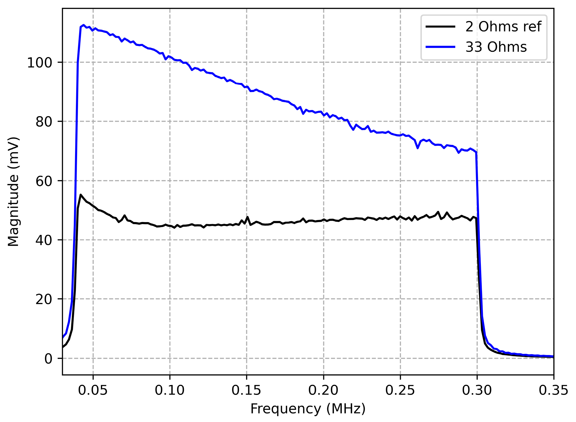
  • Measure Vac_load at J2 first for defining the reference voltage line, with a 2 Ohms resistor to obtain the ‘2 Ohms ref’ line in Figure 8;
  • Measure Vac_load at J2 with an EUT and compare the measured voltage with the previous reference voltage line to judge if the EUT impedance is larger than the minimum impedance.
  • Figure 8 shows a measurement example of a resistive load of 33 Ohms. The results show that the voltage is higher than the reference line and thus the load is compliant with the minimum impedance requirement of 2 Ohms. The aim of developing this test method is to provide one engineering method that estimates the impedance but at the same time avoids the calculation. After all, it is not easy to calculate a device impedance in a multi-source and multi-branch DC microgrid.

5. Arc Detection Based on Grid Codes Proposal

Most arc detection methods detect arc noise by analyzing current signal. This necessitates a current transformer. Normally, the current transformer should be sized based on the possible maximum current of the cable and could be bulky. Based on the proposed EMC codes and the minimum impedance requirement for loads and sources, this section proposes a novel arc detection method which extracts arc noise from voltage measurements. More details on this method can be found from the patent application EP22185243 [58].

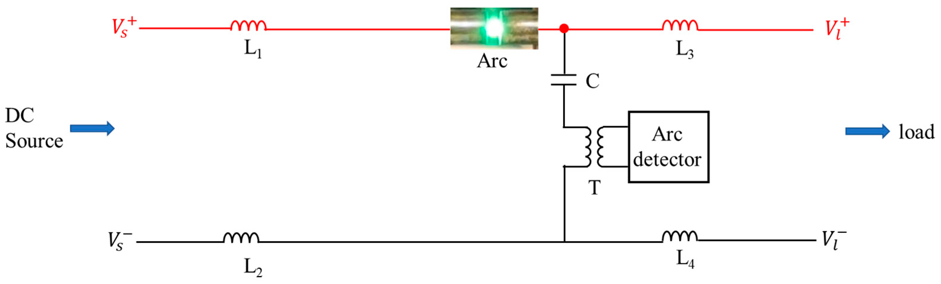
5.1. Arc Detection Circuit

Figure 9 shows the proposed new arc detection circuit in its most simple implementation. Herein a DC voltage source supplies the power to a load. The method can be applied in a more complex grid topology with multiple loads and sources as long as they satisfy the minimum impedance requirement, which is in Figure 9 warranted by having L1 to L4 sufficiently large.
In this method, the arc detector circuit can be connected in parallel to the DC grid through a DC-blocking capacitor C and can use a small coupling transformer T for safety isolation of the arc detector circuit. Because it is a parallel DC grid connection, the arc detection circuit can in principle be installed in any location of a more complex DC grid. Another benefit of this new approach is that it does not require a measurement of the arc current itself which is used in many other methods [59] but it only analyzes the voltage of the DC grid.
For an arc detection, the arc detector should analyze the voltage signal within a frequency spectrum from 40 to 100 kHz and thus will benefit from analog filters first. Second, it requires a processor to compute the time or frequency domain characteristics (like frequency spectrum) for judging whether an arc occurs or not. The detector requires an algorithm that will compare voltage characteristics before and after the arc to judge if one arc occurs.
In this new method, the minimum impedance requirement is imposed to all loads/sources connected in the frequency range of 40 kHz to 100 kHz. First, because it allows that an arc can be detected as a voltage signal without the need to measure the arc current. Second, because the arc noise voltage signal will attenuate following the cable and that if the source/load impedance is too small then the detected voltage measured will be small and might be covered by the background noise and thus arc detection might become unreliable.
The minimum impedance is proposed as two Ohms for this research. Depending on the practical application, this impedance can be increased.

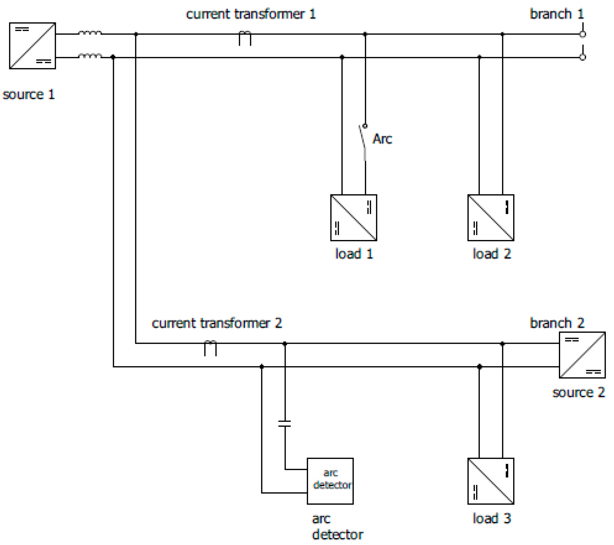
5.2. Current-Measurement-Based Arc Detection vs. Voltage-Measurement-Based Arc Detection

DC arc hazard detection today is commonly applied in photovoltaic systems and an important safety feature. Photovoltaic systems, however, are only a simple case of a DC microgrid with only the PV modules as source and the PV inverter or converter as a load. The detector with disconnector is obviously placed at the PV modules. Arc hazard detection is done based on the cable current measurement and the fine tuning of the detection algorithm is straightforward and based on the properties of the converter and modules. This solution is well known. However, this cannot be easily applied to more complicated DC microgrids with multiple sources and loads. For example, Figure 10 shows an already more complicated DC microgrid with two branches. In a DC microgrid, it is a useful feature that the detector can be in a single location and detect faults wherever in the grid, even when the arc hazard current doesn’t flow through the wires where the detector is located. For example, this is the case in Figure 10 when the arc fault is located at load 1 and directly supplied with source 1 and the detector is based on current transformer 2.
This paper proposes a new concept which only relies on voltage measurements for the application in more complex DC microgrids. In Figure 10, the current-measurement-based method requires the current transformer in each branch. The EMC grid code proposed hereafter and in particular the minimum impedance requirement will support the use of a single voltage-measurement-based arc hazard detector that can be installed at any location. As shown in Figure 10, the arc detector is installed in parallel to branch 2. If there is one arc occurring in the branch 1, the arc noise voltage will propagate to the output node of source 1, which is also connected to the arc detector in branch 2. To ensure the arc detector gets enough arc noise, the minimum impedance requirement is applied to load 3.
As a conclusion, the new proposed voltage-measurement-based arc detection makes use of the proposed EMC codes. It is more flexibly and easily implemented in complex DC microgrids.

5.3. Test Results

The developed arc detection circuit and method are tested in the platform shown in Figure 11, which includes: a DC power supply, LISN, arc generator and load [60]. Delta SM500-CP-90 is installed as the DC power supply. Customized LISNs (L-LISN 1-4) are adopted to simulate the impedances of cables connected respectively to the source and the load. A resistor bank is connected as the load.
The arc generator is shown in Figure 11b,c. It consists of a stationary part with a fixed electrode, and a movable part where the second electrode is installed. The maneuver of the movable part is achieved by regulating the speed and distance of step motor via an Arduino processor. The motor has a 1.8° step angle and 2 mm lead screw pitch, which generate a linear movement of 1 mm per 100 steps. Compared with manual arc generators, such a motor-based arc generator provides reproducible and more exact electrode movements. In addition, two types of UL 1699B [9] standard electrodes, copper and tungsten, can be selected for the platform, depending on test needs. Hence, in principle this set up simulates a broken wire following UL 1699B.
By pulling the movable electrode, an arc can be created, as shown by Figure 11c. More details about this platform are given in [60].
The arc detection circuit is connected in parallel on the load side. A 48 V DC voltage source supplies a load of 6 ohms. The positive and negative cable impedance are simulated, respectively, by L-LISN 1-2 and L-LISN 3-4. At 40 kHz, the cable impedance is approximately 2.36 ohms.
During tests, the load impedance reduces gradually to see the influence on arc detection. On the other side, the supplied energy is maintained nearly constant to provide a unified test scenario. That is to say, when the load impedance becomes smaller, the source voltage reduces correspondingly. The test cases are summarized in Table 6.
Arc noise is analyzed by the FFT functionality of Pico Scope. The Hamming window is selected. The detection results are shown in Figure 12. It is seen that when the load impedance reduces, the measured arc noise also becomes smaller. In case c, the arc noise overlaps with background noise which makes arc detection challenging. In addition, it should be said that to some extent, arc occurrence is random. The above tests were repeated several times and the most typical results are presented.
The main purpose of developing the voltage-measurement-based arc detection is to show the feasibility and advantage of proposed EMC codes. A large number of tests still should be done in different temperatures, humidity, arc gaps, and so on, as specified by the standard UL 1699B, to estimate the detection reliability, like the confidence level or false operation of arc detection.

6. Conclusions

DC microgrids are a promising solution for the future smart grids. However, EMC should be handled carefully to ensure that designed DC microgrids work as expected. To achieve this, proper EMC standards are required. Therefore, this paper first reviewed existing EMC standards in the frequency range from 9 to 500 kHz to acquire inspirations for developing EMC standards of DC microgrids. The above review was targeted to support DC arc detection and narrowband PLC in DC microgrids.
Next, new proposals were made to specify EMC requirements for electrical and electronic equipment in DC microgrids. This includes chimney-like emission limits, immunity requirements and the minimum impedance requirement. These proposals distributed particular bandwidths to arc detection (40–100 kHz) and narrowband PLC (120–300 kHz) to facilitate their implementation in DC microgrids which have so far not been covered in existing standards. A new impedance test method and immunity criteria (40–300 kHz) were also developed and validated. Such a minimum impedance requirement can support both arc detection and narrowband PLC.
Moreover, experiments were conducted on different LISNs, following existing standards CISPR 16/25 but also using an alternative LISN version being more realistic (10 µH) for a DC microgrid.
A new voltage-measurement-based arc detection was developed which is better tailored to a complex topology microgrid with multiple sources and loads in comparison to commonly applied arc detection methods in simpler PV systems. The key benefit is that a single-voltage-based arc hazard detector can be installed flexibly in DC microgrids. However, it does come at the expense of a minimum impedance requirement, which is proposed and evaluated as an additional new EMC requirement in this paper. This will require that EMC filters of switched power supplies are designed to satisfy the new requirement. The additional cost and/or volume impact can be investigated in future work. Test cases showed the influence of load impedance on the magnitude of detected arc noise. The smaller the load impedance, the smaller the magnitude of measured arc noise voltage. This justified the necessity of introducing a minimum impedance requirement.
The new EMC proposals made in this paper are based on existing standards, literature and authors’ expertise. The proposals were first applied to arc detection to investigate their feasibility and benefits. Following the advent of new technologies applicable to DC microgrids, they should be amended to support technical progress. Indeed, formulating a practical and well-accepted standard is a complex process, which necessitates a great deal of efforts from the academy and the industry. More experimental validations and investigations should be made, especially for arc hazards, which should be part of the future work. More specifically, it will require more research and gathering experimental data to define EMC threshold levels for conducted noise, immunity, and impedance, considering the microgrid applications and its characteristic parameters (cables, power level, etc.).

Author Contributions

Conceptualization, P.V.T. and D.W. (Da Wang); methodology, P.V.T. and D.W. (Da Wang); software, D.W. (Da Wang); validation, P.V.T., D.W. (Da Wang) and D.W. (Dominique Weyen); resources, P.V.T.; writing—original draft preparation, P.V.T. and D.W. (Da Wang); writing—review and editing, P.V.T., D.W. (Da Wang) and D.W. (Dominique Weyen); supervision, P.V.T.; project administration, P.V.T.; funding acquisition, P.V.T. All authors have read and agreed to the published version of the manuscript.

Funding

This research was funded by [VLAIO] grant number [Flux50 BIDC (HBC.2018.0528)] and the APC by the European Union’s Horizon Europe research and innovation program under grant agreement no. 101095863.

Data Availability Statement

No available data.

Acknowledgments

This work is funded by the funding from VLAIO for the Flux50 project BIDC (HBC.2018.0528).

Conflicts of Interest

The authors declare no conflict of interest.

References

  1. Punna, S.; Mailugundla, R.; Salkuti, S.R. Design, Analysis and Implementation of Bidirectional DC–DC Converters for HESS in DC Microgrid Applications. Smart Cities 2022, 5, 433–454. [Google Scholar] [CrossRef]
  2. Kumar, D.; Zare, F.; Ghosh, A. DC Microgrid Technology: System Architectures, AC Grid Interfaces, Grounding Schemes, Power Quality, Communication Networks, Applications, and Standardizations Aspects. IEEE Access 2017, 5, 12230–12256. [Google Scholar] [CrossRef]
  3. Mariscotti, A. Harmonic and Supraharmonic Emissions of Plug-In Electric Vehicle Chargers. Smart Cities 2022, 5, 496–521. [Google Scholar] [CrossRef]
  4. Ensini, L.; Sandrolini, L.; Thomas, D.W.P.; Sumner, M.; Rose, C. Conducted Emissions on DC Power Grids. In Proceedings of the 2018 International Symposium on Electromagnetic Compatibility (EMC EUROPE), Amsterdam, The Netherlands, 27–30 August 2018; pp. 214–219. [Google Scholar] [CrossRef]
  5. Mariscotti, A. Power Quality Phenomena, Standards, and Proposed Metrics for DC Grids. Energies 2021, 14, 6453. [Google Scholar] [CrossRef]
  6. Streubel, T.; Kattmann, C.; Eisenmann, A.; Rudion, K. Characterization of Supraharmonic Emission from Three Different Electric Vehicle Charging Infrastructures in Time and Frequency Domain. Energies 2022, 15, 394. [Google Scholar] [CrossRef]
  7. Mariscotti, A.; Sandrolini, L.; Simonazzi, M. Supraharmonic Emissions from DC Grid Connected Wireless Power Transfer Converters. Energies 2022, 15, 5229. [Google Scholar] [CrossRef]
  8. CISPR 32; Electromagnetic Compatibility of Multimedia Equipment—Emission Requirements. CISPR: Genève, Switzerland, 2019.
  9. UL 1699B; UL Standard for Safety for Arc-Fault Circuit-Interrupters. UL: Northbrook, IL, USA, 2018.
  10. Patil, D.D.; Bindu, S.; Thale, S. Arc Fault Detection in DC Microgrid Using Deep Neural Network. In Proceedings of the 2021 Biennial International Conference on Nascent Technologies in Engineering (ICNTE), Navi Mumbai, India, 15–16 January 2021. [Google Scholar]
  11. Chae, S.Y.; Park, J.J.; Oh, S. Series DC arc fault detection algorithm for DC microgrids using relative magnitude comparison. IEEE J. Emerg. Sel. Top. Power Electron. 2016, 4, 1270–1278. [Google Scholar] [CrossRef]
  12. Yao, X.; Herrera, L.; Ji, S.C.; Zou, K.; Wang, J. Characteristic study and time-domain discrete-wavelet-transform based hybrid detection of series DC arc faults. IEEE Trans. Power Electron. 2014, 29, 3103–3115. [Google Scholar] [CrossRef]
  13. Xiong, Q.; Feng, X.; Gattozzi, A.L.; Zheng, L.; Zhu, L.; Ji, S.; Hebner, R.E. Series arc fault detection and localization in DC distribution system. IEEE Trans. Instrum. Meas. 2020, 69, 122–134. [Google Scholar] [CrossRef]
  14. Sandrolini, L.; Thomas, D.W.P.; Sumner, M.; Rose, C. Measurement and evaluation of the conducted emissions of a DC/DC power converter in the frequency range 2–150 kHz. In Proceedings of the 2018 IEEE Symposium on Electromagnetic Compatibility, Signal Integrity and Power Integrity (EMC, SI & PI), Long Beach, CA, USA, 30 July–3 August 2018; pp. 345–350. [Google Scholar]
  15. Ferreira, H.C.; Lampe, L.; Newbury, J.; Swart, T.G. Power Line Communications: Theory and Applications for Narrowband and Broadband Communications over Power Lines; Wiley: Hoboken, NJ, USA, 2010. [Google Scholar]
  16. Sharma, D.; Dubey, A.; Mishra, S.; Mallik, R.K. A frequency control strategy using power line communication in a smart microgrid. IEEE Access 2019, 7, 21712–21721. [Google Scholar] [CrossRef]
  17. Shimaponda-Nawa, M.; Kolade, O.; Cheng, L. Generalized permutation coded OFDM-MFSK in hybrid powerline and visible light communication. IEEE Access 2022, 10, 20783–20792. [Google Scholar] [CrossRef]
  18. Alghamdi, B.; Cañizares, C.A. Frequency regulation in isolated microgrids through optimal droop gain and voltage control. IEEE Trans. Smart Grid 2021, 12, 988–998. [Google Scholar] [CrossRef]
  19. Shwehdi, M.H.; Khan, A.Z. A power line data communication interface using spread spectrum technology in home automation. IEEE Trans. Power Deliv. 1996, 11, 1232–1237. [Google Scholar] [CrossRef]
  20. Gassara, H.; Rouissi, F.; Ghazel, A. Statistical Characterization of the Indoor Low-Voltage Narrowband Power Line Communication Channel. IEEE Trans. Electromagn. Compat. 2014, 56, 123–131. [Google Scholar] [CrossRef]
  21. Wang, D.; Weyen, D.; Van Tichelen, P. Review on EMC Standards (9–500 kHz) for DC Microgrids to Support Arc Fault Detection & Power Line Communication and its Potential Application in Hybrid Ships. In Proceedings of the 2023 IEEE International Conference on Electrical Systems for Aircraft, Railway, Ship Propulsion and Road Vehicles & International Transportation Electrification Conference (ESARS-ITEC), Venice, Italy, 29–31 March 2023. [Google Scholar]
  22. EN 62606; General Requirements for Arc Fault Detection Devices. CENELEC: Bruxelles, Belgium, 2014.
  23. IEC 63027; DC arc Detection and Interruption in Photovoltaic Power Systems. IEC: Genève, Switzerland, 2023.
  24. EN 50065-1; Signaling on Low-Voltage Electrical Installations in the Frequency Range 3 kHz to 148,5 kHz—General Requirements, Frequency Bands and Electromagnetic Disturbances. CENELEC: Bruxelles, Belgium, 2012.
  25. EN 50090-5-1; Home and Building Electronic Systems (HBES)—Media and Media Dependent Layers—Power Line for HBES Class 1. 2020. Available online: https://www.etsi.org/deliver/etsi_tr/105100_105199/1051740501/01.01.01_60/tr_1051740501v010101p.pdf (accessed on 30 June 2023).
  26. IEEE Std 1901.2-2013; IEEE Standard for Low-Frequency (Less than 500 kHz) Narrowband Power Line Communications for Smart Grid Applications. 2013. Available online: https://ieeexplore.ieee.org/document/6679210 (accessed on 31 May 2023).
  27. G3 PLC Standard. Available online: https://g3-plc.com/g3-plc/ (accessed on 31 May 2023).
  28. PRIME Standard. Available online: https://www.prime-alliance.org/alliance/specification/ (accessed on 31 May 2023).
  29. CISPR 16-1-1; Specification for Radio Disturbance and Immunity Measuring Apparatus and Methods—Part 1-1: Radio Disturbance and Immunity Measuring Apparatus—Measuring Apparatus. CISPR: Genève, Switzerland, 2019.
  30. CISPR 25; Vehicles, Boats and Internal Combustion Engines—Radio Disturbance Characteristics—Limits and Methods of Measurement for the Protection of on-Board Receivers. CISPR: Genève, Switzerland, 2021.
  31. EN 61000-6-3; Electromagnetic Compatibility (EMC)—Part 6-3: Generic Standards—Emission Standard for Equipment in Residential Environments. CENELEC: Bruxelles, Belgium, 2007.
  32. EN 61000-4-6; Electromagnetic Compatibility (EMC)—Part 4-6: Testing and Measurement Techniques—Immunity to Conducted Disturbances, Induced by Radio-Frequency Fields. CENELEC: Bruxelles, Belgium, 2015.
  33. EN 55011; Industrial, Scientific and Medical Equipment—Radio-Frequency Disturbance Characteristics—Limits and Methods of Measurement. CENELEC: Bruxelles, Belgium, 2016.
  34. EN 55014-1; Electromagnetic Compatibility—Requirements for Household Appliances, Electric Tools and Similar Apparatus—Part 1: Emission. CENELEC: Bruxelles, Belgium, 2017.
  35. EN 55015; Limits and Methods of Measurement of Radio Disturbance Characteristics of Electrical Lighting and Similar Equipment. CENELEC: Bruxelles, Belgium, 2019.
  36. EN 55016-2-1; Specification for Radio Disturbance and Immunity Measuring Apparatus and Methods Part 2-1: Methods of Measurement of Disturbances and Immunity—Conducted Disturbance Measurements. CENELEC: Bruxelles, Belgium, 2018.
  37. EN 55016-2-3; Specification for Radio Disturbance and Immunity Measuring Apparatus and Methods Part 2-3: Methods of Measurement of Disturbances and Immunity—Radiated Disturbance Measurements. CENELEC: Bruxelles, Belgium, 2017.
  38. EN 55022; Information Technology Equipment—Radio Disturbance Characteristics—Limits and Methods of Measurement. CENELEC: Bruxelles, Belgium, 2012.
  39. EN 55032; Electromagnetic Compatibility of Multimedia Equipment—Emission Requirements. CENELEC: Bruxelles, Belgium, 2013.
  40. EN-IEC 61851-21-2; Electric Vehicle Conductive Charging System—Part 21-2: Electric Vehicle Requirements for Conductive Connection to an AC/DC Supply—EMC Requirements for Off Board Electric Vehicle Charging Systems. CENELEC: Bruxelles, Belgium, 2021.
  41. CISPR 16-1-2; Specification for Radio Disturbance and Immunity Measuring Apparatus and Methods—Part 1-2: Radio Disturbance and Immunity Measuring Apparatus—Coupling Devices for Conducted Disturbance Measurements. CISPR: Genève, Switzerland, 2021.
  42. Yudhistira, Y.; Mandaris, D.; Yoppy, Y.; Hamdani, D.; Rachmilda, T.D.; Nurman, F.A. Comparative Analysis of Conducted Emission of Off-Grid PV Inverter Using Different DC- LISN s. In Proceedings of the 2021 Asia-Pacific International Symposium on Electromagnetic Compatibility (APEMC), Nusa Dua, Bali, Indonesia, 27–30 September 2021; pp. 1–4. [Google Scholar] [CrossRef]
  43. Kerfin, O.; Harm, M.; Willmann, B. Reference Setup for RF Impedance Measurements with High DC Bias Currents. In Proceedings of the 2019 International Symposium on Electromagnetic Compatibility—EMC EUROPE, Barcelona, Spain, 2–6 September 2019; pp. 997–1002. [Google Scholar] [CrossRef]
  44. Jiang, L.; Wang, F.; Szolusha, K.; Mathews, K. A Practical Method for Separating Common-Mode and Differential-Mode Emissions in Conducted Emissions Testing. Analog. Dialogue Mag. 2021, 55, 1–4. [Google Scholar]
  45. EN 61000-6-1; Electromagnetic Compatibility (EMC)—Part 6-1: Generic STANDARDS IMMUNITY for Residential, Commercial and Light Industrial Environments. CENELEC: Bruxelles, Belgium, 2019.
  46. EN 61000-6-2; Electromagnetic Compatibility (EMC)—Part 6-2: Generic STANDARDS IMMUNITY for Industrial Environments. CENELEC: Bruxelles, Belgium, 2019.
  47. EN 55014-2; Electromagnetic Compatibility—Requirements for Household Appliances, Electric Tools and Similar Apparatus—Part 2: Immunity. CENELEC: Bruxelles, Belgium, 2015.
  48. EN 55024; Information Technology Equipment—Immunity Characteristics—Limits and Methods of Measurement. CENELEC: Bruxelles, Belgium, 2011.
  49. IEC TR 63282; LVDC Systems—Assessment of Standard Voltages and Power Quality Requirements. IEC: Genève, Switzerland, 2020.
  50. Huynh, H.A.; Han, Y.; Park, S.; Hwang, J.; Song, E.; Kim, S. Design and Analysis of the DC–DC Converter with a Frequency Hopping Technique for EMI Reduction. IEEE Trans. Compon. Packag. Manuf. Technol. 2018, 8, 546–553. [Google Scholar] [CrossRef]
  51. Hamza, D.; Al Hosani, K.H. DC-link input EMI filter design in a centralized architecture PV inverter: Impedance approach. In Proceedings of the 2014 IEEE Energy Conversion Congress and Exposition (ECCE), Pittsburgh, PA, USA, 14–18 September 2014; pp. 4777–4783. [Google Scholar] [CrossRef]
  52. Lu, J.; Tong, X.; Zeng, J.; Shen, M.; Yin, J. Efficiency Optimization Design of L-LLC Resonant Bidirectional DC-DC Converter. Energies 2021, 14, 3123. [Google Scholar] [CrossRef]
  53. Agbemuko, A.J.; Domínguez-García, J.L.; Prieto-Araujo, E.; Gomis-Bellmunt, O. Impedance Modelling and Parametric Sensitivity of a VSC-HVDC System: New Insights on Resonances and Interactions. Energies 2018, 11, 845. [Google Scholar] [CrossRef] [Green Version]
  54. Khilnani, A.; Wan, L.; Sumner, M.; Thomas, D.; Hamid, A.; Grassi, F. Conducted Emissions Measurements in DC Grids: Issues in Applying Existing LISN Topologies and Possible Solutions. In Proceedings of the 2021 IEEE 15th International Conference on Compatibility, Power Electronics and Power Engineering (CPE-POWERENG), Florence, Italy, 14–16 July 2021; pp. 1–6. [Google Scholar] [CrossRef]
  55. Alenius, H. Modeling and Electrical Emulation of Grid Impedance, for Stability Studies of Grid-Connected Converters. Master’s Thesis, Tampere University of Technology, Tampere, Finland, 2017. [Google Scholar]
  56. Fernández, I.; de la Vega, D.; Roggo, D.; Stiegler, R.; Capponi, L.; Angulo, I.; Meyer, J.; Arrinda, A. Comparison of Measurement Methods of LV Grid Access Impedance in the Frequency Range Assigned to Nb-Plc Technologies. Electronics 2019, 8, 1155. [Google Scholar] [CrossRef] [Green Version]
  57. Hallemans, L.; Ravyts, S.; Govaerts, G.; Fekriasl, S.; Van Tichelen, P.; Driesen, J. A stepwise methodology for the design and evaluation of protection strategies in LVDC microgrids. Appl. Energy 2022, 310, 118420. [Google Scholar] [CrossRef]
  58. Van Tichelen, P.; Wang, D. Method and System for Detecting Arcs in a DC Grid, and Method of Checking Compliance of Electrical Devices for Connection to Said DC Grid. Europe Patent Application EP22185243.7, 15 July 2022. [Google Scholar]
  59. Ahn, J.B.; Jo, H.B.; Ryoo, H.J. Real-Time DC Series Arc Fault Detection Based on Noise Pattern Analysis in Photovoltaic System. IEEE Trans. Ind. Electron. 2023, 70, 10680–10689. [Google Scholar] [CrossRef]
  60. Wang, D.; Tichelen, P.V. Noise in DC Systems and the Potential Influence on Arc Detection. In Proceedings of the 2022 20th International Conference on Harmonics & Quality of Power (ICHQP), Naples, Italy, 29 May–1 June 2022. [Google Scholar]
Figure 1. Conducted emission limits in EN 50065.
Electronics 12 03122 g001
Figure 2. Overview of conducted emission limits on DC power ports according to EN 55032 or CISPR 32 [8].
Electronics 12 03122 g002
Figure 3. Electromagnetic emissions examples. (a) Floor lamp. (b) Refrigerator. (c) Raspberry PI 4.
Electronics 12 03122 g003
Figure 4. The proposed EMC conducted emission limits for electrical equipment in DC microgrids.
Electronics 12 03122 g004
Figure 5. Circuit of customized 10 µH LISN.
Electronics 12 03122 g005
Figure 6. Voltage divider concept for impedance tests.
Electronics 12 03122 g006
Figure 7. Impedance test method.
Electronics 12 03122 g007
Figure 8. Voltage measurements for 2 Ohms and 33 Ohms.
Electronics 12 03122 g008
Figure 9. Arc detection circuit.
Electronics 12 03122 g009
Figure 10. Arc detection in a 2-branch microgrid.
Electronics 12 03122 g010
Figure 11. Arc test platform.
Electronics 12 03122 g011
Figure 12. Arc noise measurements.
Electronics 12 03122 g012
Table 1. Conducted emission limits of EN 50065 for single-phase devices.
Class3–9 kHz9–95 kHz95–148.5 kHz
122134 dBµV134–120 dBµV122 dBµV
134134 dBµV134–120 dBµV134 dBµV
Table 2. EMC emission standards for various equipment regarding AC and DC.
StandardTitle
CISPR 16-1-1 or EN IEC 55016-1-1 [29]Specification for radio disturbance and immunity measuring apparatus and methods—Part 1-1: Radio disturbance and immunity measuring apparatus—Measuring apparatus
CISPR 25 or EN 55025 [30]Vehicles, boats and internal combustion engines—Radio disturbance characteristics—Limits and methods of measurement for the protection of on-board receivers
EN 61000-6-3 [31]Electromagnetic compatibility (EMC)—Part 6-3: Generic standards—Emission standard for equipment in residential environments
EN 61000-6-4 [32]Electromagnetic compatibility (EMC)—Part 6-4: Generic standardsEmission standard
for industrial environments
EN 55011 [33]Industrial, scientific and medical equipment - Radio-frequency disturbance characteristics - Limits and methods of measurement
EN 55014-1 [34]Electromagnetic compatibility—Requirements for household appliances, electric tools and similar apparatus—Part 1: Emission
EN 55015 [35]Limits and methods of measurement of radio disturbance characteristics of electrical lighting and similar equipment
EN 55016-2-1 [36]Specification for radio disturbance and immunity measuring apparatus and methods Part 2-1: Methods of measurement of disturbances and immunity—Conducted disturbance measurements
EN 55016-2-3 [37]Specification for radio disturbance and immunity measuring apparatus and methods Part 2-3: Methods of measurement of disturbances and immunity—Radiated disturbance measurements
EN 55022 [38]Information technology equipment—Radio disturbance characteristics—Limits and methods of measurement
EN 55032 [39]Electromagnetic compatibility of multimedia equipment—Emission requirements
EN-IEC 61851-21-2:2021 [40]Electric vehicle conductive charging system—Part 21-2: Electric vehicle requirements for conductive connection to an AC/DC supply—EMC requirements for off board electric vehicle charging systems
Table 3. EN EMC immunity standards for various equipment applicable to both AC and DC.
StandardTitle
EN 61000-6-1 [45]Electromagnetic compatibility (EMC)—Part 6-1: Generic standards Immunity for residential, commercial and light industrial environments
EN 61000-6-2 [46]Electromagnetic compatibility (EMC)—Part 6-2: Generic standards
Immunity for industrial environments
EN 61000-4-6 [32]Electromagnetic compatibility (EMC)—Part 4-6:
Testing and measurement techniques—Immunity to conducted disturbances, induced by radio-frequency fields
EN 55014-2 [47]Electromagnetic compatibility—Requirements for household appliances, electric tools and similar apparatus—Part 2: Immunity
EN 55024 [48]Information technology equipment—Immunity characteristics—Limits and methods of measurement
EN-IEC 61851-21-2:2021 [40]Electric vehicle conductive charging system—Part 21-2: Electric vehicle requirements for conductive connection to an AC/DC supply—EMC requirements for off board electric vehicle charging systems
Table 4. Set-up for electromagnetic emissions tests.
CasePower SupplyConverterLoad
aDelta
SM500-CP-90
NoFloor lamp
bDelta
SM500-CP-90
Victron Orion 48/24-5Refrigerator
cDelta
SM500-CP-90
LM2596HVS 48/5Raspberry PI 4
Table 5. Frequency spectrum allocation for DC grids.
DeviceFrequency Bands
Arc detection40–100 kHz (current or voltage sensing to monitor the emission spectrum of connected noise sources and for lamps also no risk to create interference with IR remote controllers)
Power line communication120 kHz–300 kHz
Recommended switching frequencies for converters>300 kHz most recommended (because no interference is expected in PLC and arc detection)
100–120 kHz (because the third harmonic is above 300 kHz and therefore no interference is expected in PLC and arc detection)
33–40 kHz for converters but not for converters that supply lamps (because this will avoid interference from third harmonics to Arc detection/PLC + not applicable to lamp drivers. This will cause interference with IR remote controllers)
13 kHz for converters if none of the previous options can be applied and thus still allow a third harmonic emission below the frequency band of 40 kHz.
Table 6. Arc test scenarios.
CaseVoltage (V)Load Impedance (Ohm)Source Power (W)
a48.006.00 384.00
b39.204.00384.16
c33.943.00383.97
Disclaimer/Publisher’s Note: The statements, opinions and data contained in all publications are solely those of the individual author(s) and contributor(s) and not of MDPI and/or the editor(s). MDPI and/or the editor(s) disclaim responsibility for any injury to people or property resulting from any ideas, methods, instructions or products referred to in the content.

