
Assessment of a Functional Electromagnetic Compatibility Analysis of Near-Body Medical Devices Subject to Electromagnetic Field Perturbation


Abstract
:1. Introduction
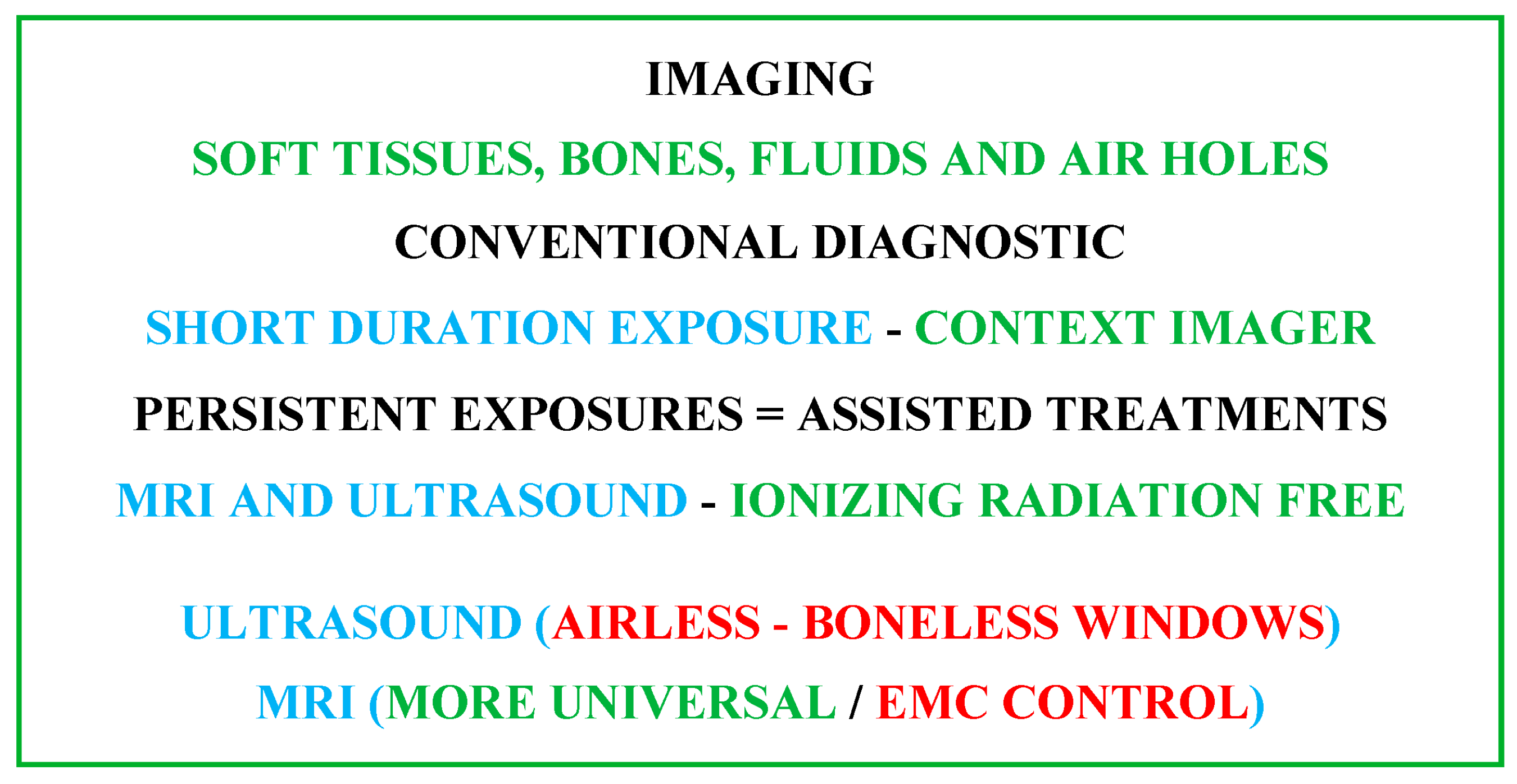
2. Imaging Methodologies
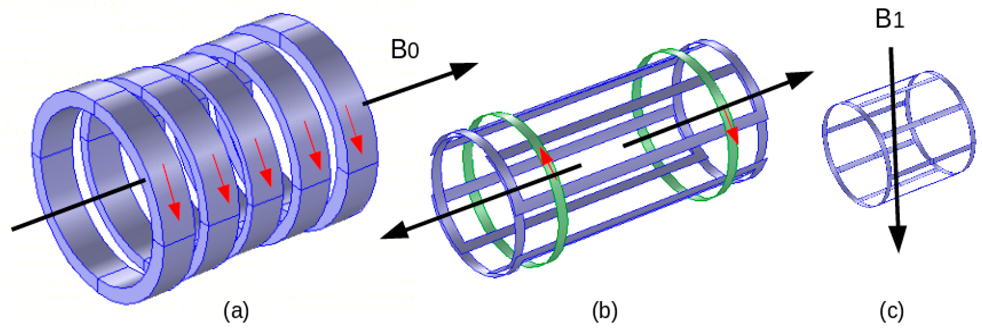
2.1. MRI Constituents
2.2. Features of MRI Fields B0, G(x, y, z) and B1
2.3. MRI Compatibility
2.4. Image Artifacts
3. MRI-Assisted Robotic Treatments
3.1. Robotic External Matter Introductions
3.2. MRI-Compatible Materials
3.3. Conformity Control of MRI Compatibility
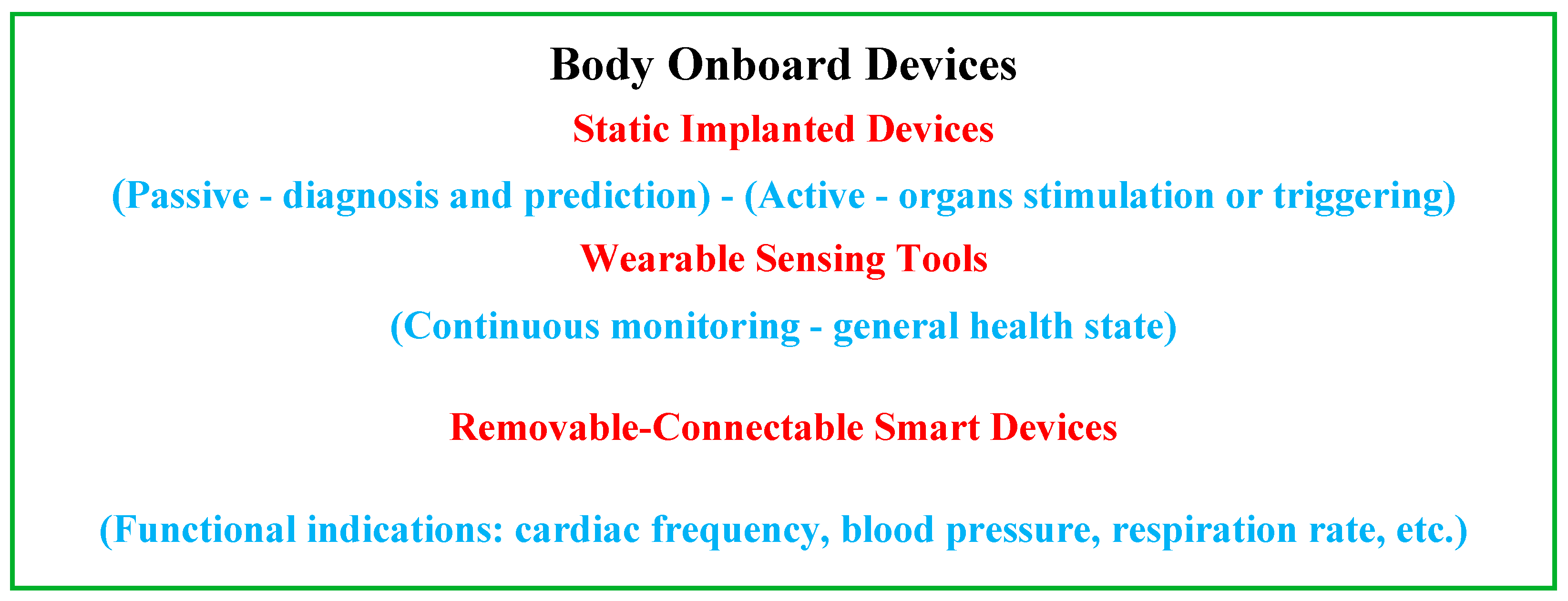
4. Embedded, Wearable and Detachable Devices
4.1. EMF Perturbation Control of Onboard Devices
4.2. Onboard Device Shielding Protection Technologies
5. Functional EMC Control
5.1. EMF Governing Equations
EMF Equation Solution and EMC
5.2. Body Numerical Virtual Models
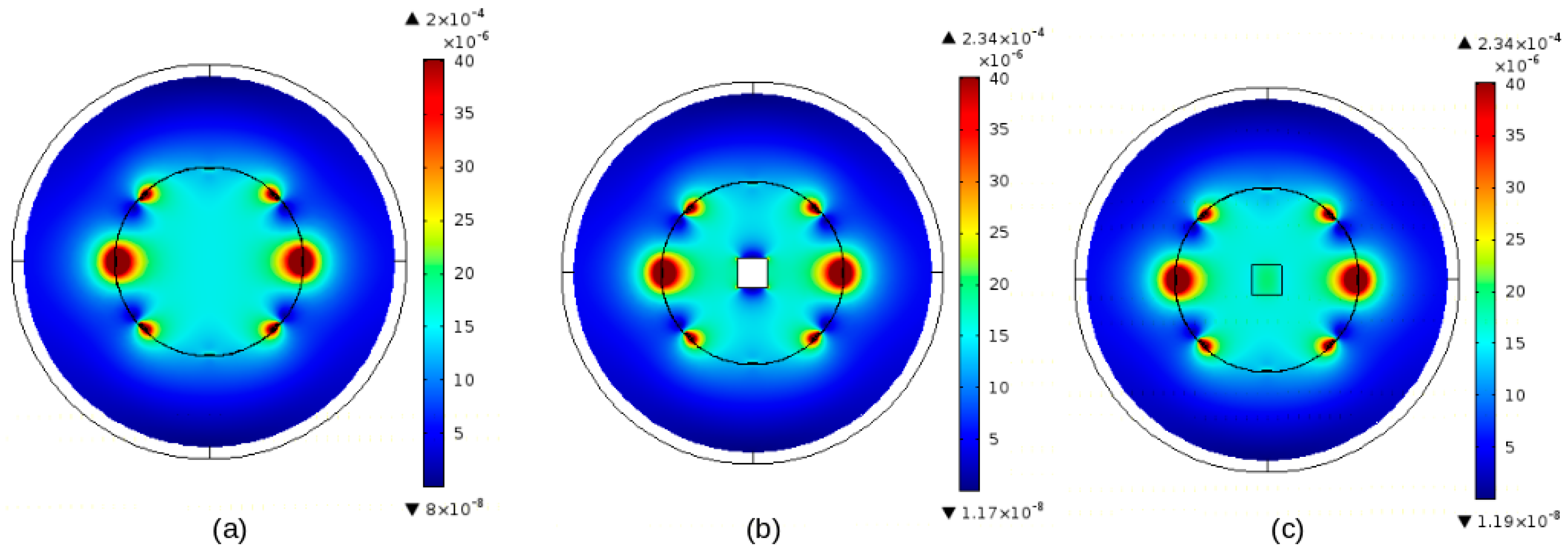
5.3. Qualitative Methodology Case Study Example
6. Discussion
- Implanted treatments are considered in Section 3 and Section 4 in two different situations. This includes the case of implanted treatment that needs movement or location control with augmented accuracy, which has been considered in Section 3 regarding image-assisted treatments. The other concerned static passive and active implanted devices considered in Section 4 are in regard to onboard autonomous devices. The difference between these two cases in relation to the disturbance of EMF noise is that in the first, the procedure implemented with the treatment could disrupt the functioning of the assisting MRI, while in the second, an external exposure source could disrupt the operation of the implanted onboard device.
- As discussed in Section 5.2, regarding EMC control using a mathematical modeling analysis, the incorporation of virtual phantoms representing the patient’s tissues involved in the medical treatment using the disturbed device might be necessary. This allows taking into account more realistic operating conditions for medical devices under control. Such a check is provided separately to guarantee the proper functioning of the device. However, in certain cases, this functioning could be linked to neighboring tissues and, in particular, under exposure to EMF. In fact, EMF exposure can produce biological thermal effects in living tissues that may be greater with longer durations. Under such conditions, consideration of virtual phantoms in the control model permits the consideration of an unshielded device malfunction effect associated with a biological thermal effect due to EMF exposure. It should be noted that such a malfunction could lead to tissue heating caused by heated metal parts involved in the device. Additionally, in the case of shielded onboard devices, the shielding materials are often electrically conductive. Even if the device in this case is protected from exposure to EMFs, the induced currents can heat the metal of the shield, which can cause tissue heating. This thermal behavior mainly concerns onboard devices, which may be subject to long EMF exposure intervals. In the case of image-assisted treatments, it may be noted that the MRI RF field exposure to the body tissues occurs for short intervals.
- In the case of onboard devices exposed to EMF waves, we consider four options for exposure. The first concerns devices made of materials insensitive to EMF (no magnetic or conductive material); in this case, exposure to electromagnetic fields will not disrupt the device but can only affect living tissue. The second case concerns devices comprising materials sensitive to EMF (magnetic and/or conductive material). In such a case, the device will be disturbed by EMF exposure and the tissues will be affected directly by the exposure and indirectly by the disturbed device. The third case concerns the last device but shielded with a simple conductive material. In this case, the exposure will not disrupt the operation of the device, but the tissues will be affected directly by the exposure and indirectly by the shield. The fourth option concerns the adaptation of the conductive nature of the shielding. Indeed, electromagnetic radiation shielding is corroborated by two basic loss types, reflection and absorption losses. In the occurrence of a conductive shield, the surface electric impedance can be written as a function of electromagnetic parameters, as Zs = (ω · μ/σ) 1/2. This impedance is much lower than the free space impedance Z0 = (μ0/ε0) 1/2 ≈ 376.7 ohm. If a plane field wave hits the shield, a high impedance discrepancy triggers strong reflections. The surviving field is conveyed across the shield after part absorption. The radiated field with elevated frequencies, e.g., RF, only infiltrates the close surface section of a conductor, due to a skin effect. The depth of penetration δ (skin depth) can be expressed as δ = (ω · μ · σ/2) −1/2. Note that this expression is only utilizable if δ is superior to the mean free path of an electron within the material. Regarding the losses due to reflection and absorption, the first diminishes with the frequency while the second, which is correlated to the thickness of the shield, rises with the frequency. The total sum of these losses represents the total shielding (screening) effectiveness (SE), which is termed as the ratio of strengths of EMFs without and with the shielded device. Thus, in the last option regarding the adaptation of the conductive nature of the shielding, the use of multifunctional matched materials for low-reflectivity EMI shielding can provide improved protection. The material tailoring can reduce the strong EM reflection caused by the high conductivity of the material. Additionally, a specific manufacturing process can reduce the reflected power coefficient of the material, added to reduced losses and improved thermal insulation and environmentally friendly shielding materials; see, e.g., [128,129,130]. In conclusion, only a device made from EMF-insensitive materials or elegantly shielded, and exposed to EMF for a short interval, can be safe.
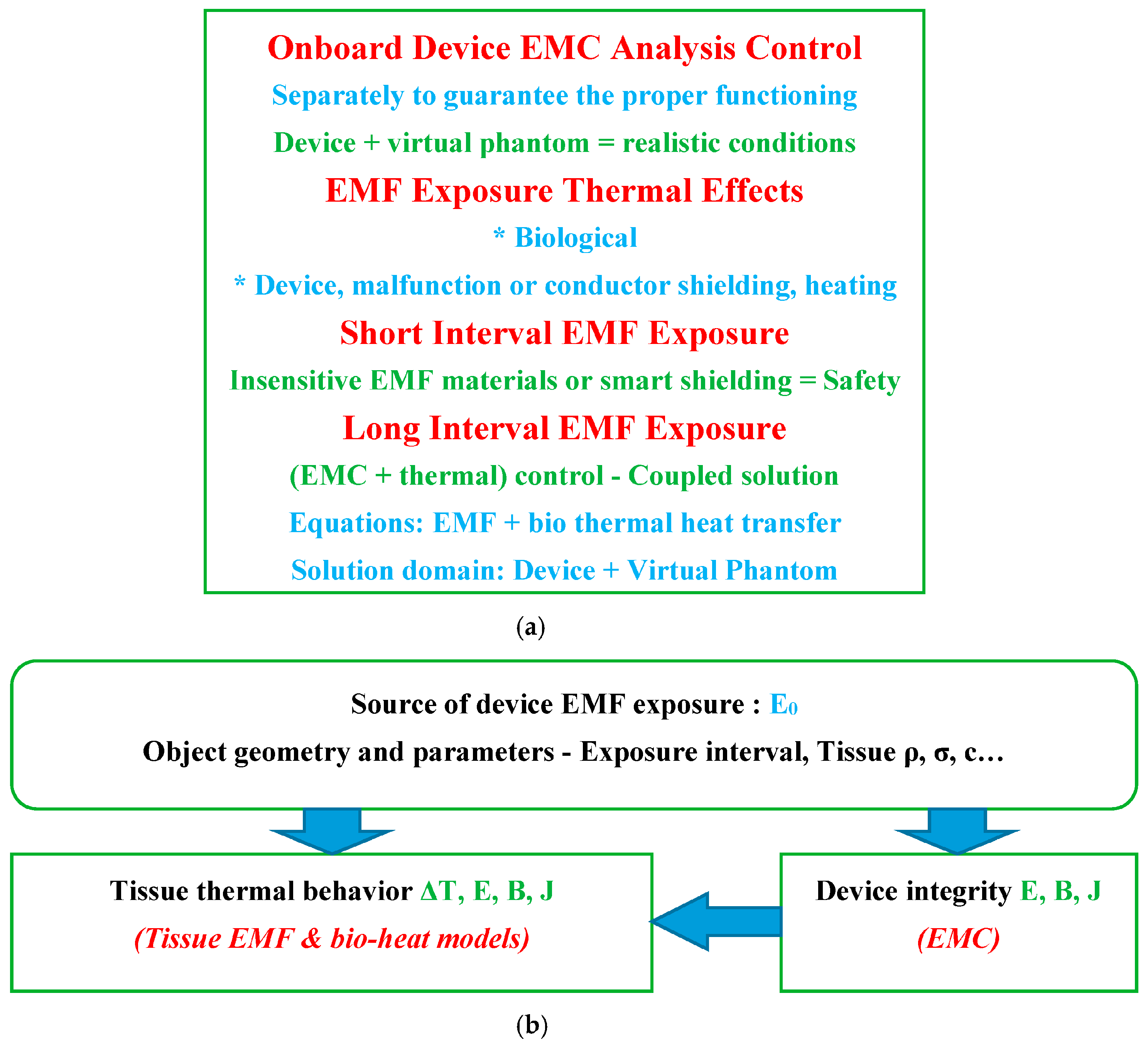
- In case of continuous or prolonged exposure to EMF waves of onboard devices working near human tissues, EMC monitoring of the device must be accompanied by an assessment of tissue heating. This can be accomplished by a coupled solution of the EMF-bio thermal heat transfer equations [33,102,131]. Indeed, the thermal behavior of tissues can be determined from the EMF power loss dissipated, in the tissues on one side and in conductive metals of unshielded devices or in simple conductive shields of devices on the other side. These dissipated losses can be calculated from the induced EMFs obtained from the 3D solution of Equations (1)–(4). The value of this EMF power loss can be used as the input heat source in the 3D solution of the heat transfer equation. Such a solution provides access to the ΔT distribution of the temperature rise in the solution domain of concern. The thermal behavior in living tissues is governed by Penne’s bio-heat equation [33,102,131]. Note that dissipated power density Pd = σ · E2/2 is in conductors and Pd = ω · ε″· E2/2 in is dielectrics (tissues), where E is the absolute peak value of the electric field strength in V·m−1, ε″ is the imaginary part of the complex permittivity of the absorbing material in F·m−1 and the dissipated power density Pd is in W·m−3. Penne’s bio-heat equation is given with c ρ ∂T/∂t = ∇ · (k ∇T) + Pd + qmet − Cb ρb ωb (T − Tb). In this equation, c is the specific heat in J· kg−1·°C−1, k is thermal conductivity in W·m−1∙°C−1 and ρ is density in kg·m−3 of the substance. T is local temperature in °C, qmet is the basal metabolic heat source in W·m−3, cb is blood-specific heat in J·kg−1·°C−1, ρb is blood density in kg·m−3, ωb is the blood perfusion rate in 1/s and Tb is the blood temperature in °C. The term ∇·(k∇T) symbolizes the heat equation in a differential form. Figure 5 illustrates the control strategies for onboard devices in case of exposure to EMF, involving the exposure interval, device integrity and temperature rise in living body tissues.
- Following the example given in Section 5.3, concerning the distribution of the RF field under the effect of the introduction of external materials, certain details deserve to be underlined. The first concerns the characteristics of matter affecting the modification of the field distribution. These involve, in addition to physical behavior, the size, shape and orientation in space in relation to the direction of the field. The size is directly related to the importance of the disturbance of the field distribution. For very small sizes, generally the disturbances could be negligible or easily compensated. Magnetic materials are the most disruptive around its volume and should be avoided. Dielectric materials are practically non-disruptive. Disturbances linked to conductive materials are strongly linked to shape and spatial orientation. The larger the surface of the conductor perpendicular to the axis of B1, the greater the induced eddy currents and associated field disturbances will be. Thus, a conductive sheet of insignificant thickness positioned parallel to the field will hardly disturb the field distribution. This observation may facilitate the use of thin electrodes for properly positioned devices in the RF coil without field disturbance. Typical examples of non-disruptive field distribution could be piezoelectric sensors and actuators composed of piezoelectric stacks, which behave dielectrically, equipped with thin sheet electrodes, which can be controlled to be parallel to the field direction [46,47,48,49,50,51,52,53,54,55,121].
7. Conclusions
- Image-assisted robotics involving MRI and piezoelectric devices offer support for patient well-being.
- Conductive materials can be introduced into the MRI subject to particular shapes and spatial orientation in addition to EMC verification.
- Embedded devices constructed from EMF-insensitive materials or intelligently shielded can be used safely with short EMF exposure intervals.
- In case of continuous or prolonged EMF exposure, the increase in body tissue temperature must be supervised in addition to EMC monitoring.
- The use of virtual tissue models in EMC testing allows for more realistic evaluation capabilities.
Funding
Conflicts of Interest
References
- Petroulakis, N.; Mattsson, M.O.; Chatziadam, P.; Simko, M.; Gavrielides, A.; Yiorkas, A.M.; Zeni, O.; Scarfi, M.R.; Soudah, E.; Otin, R.; et al. NextGEM: Next-Generation Integrated Sensing and Analytical System for Monitoring and Assessing Radiofrequency Electromagnetic Field Exposure and Health. Int. J. Environ. Res. Public Health 2023, 20, 6085. [Google Scholar] [CrossRef]
- Henschenmacher, B.; Bitsch, A.; de Las Heras Gala, T.; Forman, H.J.; Fragoulis, A.; Ghezzi, P.; Kellner, R.; Koch, W.; Kuhne, J.; Sachno, D.; et al. The effect of radiofrequency electromagnetic fields (RF-EMF) on biomarkers of oxidative stress in vivo and in vitro: A protocol for a systematic review. Environ. Int. 2022, 158, 106932. [Google Scholar] [CrossRef]
- Hamed, T.; Maqsood, M. SAR Calculation & Temperature Response of Human Body Exposure to Electromagnetic Radiations at 28, 40 and 60 GHz mm Wave Frequencies. Prog. Electromagn. Res. M 2018, 73, 47–59. [Google Scholar] [CrossRef]
- Lagorio, S.; Blettner, M.; Baaken, D.; Feychting, M.; Karipidis, K.; Loney, T.; Orsini, N.; Röösli, M.; Paulo, M.S.; Elwood, M. The effect of exposure to radiofrequency fields on cancer risk in the general and working population: A protocol for a systematic review of human observational studies. Environ. Int. 2021, 157, 106828. [Google Scholar] [CrossRef] [PubMed]
- Romeo, S.; Zeni, O.; Sannino, A.; Lagorio, S.; Biffoni, M.; Scarfì, M.R. Genotoxicity of radiofrequency electromagnetic fields: Protocol for a systematic review of in vitro studies. Environ. Int. 2021, 148, 106386. [Google Scholar] [CrossRef] [PubMed]
- Pophof, B.; Burns, J.; Danker-Hopfe, H.; Dorn, H.; Egblomasse-Roidl, C.; Eggert, T.; Fuks, K.; Henschenmacher, B.; Kuhne, J.; Sauter, C.; et al. The effect of exposure to radiofrequency electromagnetic fields on cognitive performance in human experimental studies: A protocol for a systematic review. Environ. Int. 2021, 157, 106783. [Google Scholar] [CrossRef] [PubMed]
- Kovács, A.; Bischoff, P.; Haddad, H.; Kovács, G.; Schaefer, A.; Zhou, W.; Pinkawa, M. Personalized Image-Guided Therapies for Local Malignencies: Interdisciplinary Options for Interventional Radiology and Interventional Radiotherapy. Front. Oncol. 2021, 11, 616058. [Google Scholar] [CrossRef] [PubMed]
- Zhao, J.; Zhi, Z.; Zhang, H.; Zhao, J.; Di, Y.; Xu, K.; Ma, C.; Liu, Z.; Sui, A.; Wang, J. Efficacy and safety of CT guided 125I brachytherapy in elderly patients with non small cell lung cancer. Oncol. Lett. 2020, 20, 183–192. [Google Scholar] [CrossRef] [PubMed]
- Park, B.K. Ultrasound-guided genitourinary interventions: Principles and techniques (Review Article). Ultrasonography 2017, 36, 336–348. [Google Scholar] [CrossRef]
- Pinto, P.A.; Chung, P.H.; Rastinehad, A.R.; Baccala, A.A., Jr.; Kruecker, J.; Benjamin, C.J.; Xu, S.; Yan, P.; Kadoury, S.; Chua, C.; et al. Magnetic resonance imaging/ultrasound fusion guided prostate biopsy improves cancer detection following transrectal ultrasound biopsy and correlates with multiparametric magnetic resonance imaging. J. Urol. 2011, 186, 1281–1285. [Google Scholar] [CrossRef]
- Fiard, G.; Hohn, N.; Descotes, J.L.; Rambeaud, J.J.; Troccaz, J.; Long, J.A. Targeted MRI-guided prostate biopsies for the detection of prostate cancer: Initial clinical experience with real-time 3-dimensional transrectal ultrasound guidance and magnetic resonance/transrectal ultrasound image fusion. Urology 2013, 81, 1372–1378. [Google Scholar] [CrossRef]
- Veltri, A.; Garetto, I.; Pagano, E.; Tosetti, I.; Sacchetto, P.; Fava, C. Percutaneous RF thermal ablation of renal tumors: Is US guidance really less favorable than other imaging guidance techniques? Cardiovasc. Intervent. Radiol. 2009, 32, 76–85. [Google Scholar] [CrossRef] [PubMed]
- Bassignani, M.; Moore, Y.; Watson, L.; Theodorescu, D. Pilot experience with real-time ultrasound guided percutaneous renal mass cryoablation. J. Urol. 2004, 171, 1620–1623. [Google Scholar] [CrossRef]
- Guk, K.; Han, G.; Lim, J.; Jeong, K.; Kang, T.; Lim, E.-K.; Jung, J. Evolution of Wearable Devices with Real-Time Disease Monitoring for Personalized Healthcare. Nanomaterials 2019, 9, 813. [Google Scholar] [CrossRef]
- Xin, Y.; Liu, T.; Sun, H.; Xu, Y.; Zhu, J.; Qian, C.; Lin, T. Recent progress on the wearable devices based on piezoelectric sensors. Ferroelectrics 2018, 531, 102–113. [Google Scholar] [CrossRef]
- Yetisen, A.K.; Martinez-Hurtado, J.L.; Ünal, B.; Khademhosseini, A.; Butt, H. Wearables in Medicine. Adv. Mater. 2018, 30, 1706910. [Google Scholar] [CrossRef]
- Sener, T.; Haenen, W.; Smits, P.; Hans, G.H. Large-scale real-life implementation of technology-enabled care to maximize hospitals’ medical surge preparedness during future infectious disease outbreaks and winter seasons: A viewpoint. Front. Public Health 2023, 11, 1149247. [Google Scholar] [CrossRef]
- Navarro-Valverde, C.; Ramos-Maqueda, J.; Romero-Reyes, M.J.; Esteve-Ruiz, I.; García-Medina, D.; Pavón-Jiménez, R.; Rodríguez-Gómez, C.; Leal-del-Ojo, J.; Cayuela, A.; Molano-Casimiro, F.J. Magnetic resonance imaging in patients with cardiac implantable electronic devices: A prospective study. Magn. Reson. Imaging 2022, 91, 9–15. [Google Scholar] [CrossRef]
- Hirano, M.; Muto, Y.; Kuroda, M.; Fujiwara, Y.; Sasaki, T.; Kuroda, K.; Kamizaki, R.; Imajoh, S.; Tanabe, Y.; Al-Hammad, W.E.; et al. Quantitative evaluation of the reduction of distortion and metallic artifacts in magnetic resonance images using the multiacquisition variable resonance image combination selective sequence. Exp. Ther. Med. 2023, 25, 109. [Google Scholar] [CrossRef] [PubMed]
- Amann, N.; Johnson, S.; Chagarlamudi, K.; Gupta, A.; Faraji, N. Scheduling Musculoskeletal MRI for Patients with Metallic Hardware: Initial Observations on Decreasing Nondiagnostic and Repeat Examinations at a Multisite Academic Medical Center. Curr. Probl. Diagn. Radiol. 2023, 52, 327–329. [Google Scholar] [CrossRef] [PubMed]
- Fujiwara, Y.; Sasaki, T.; Muto, Y.; Hirano, M.; Kamizaki, R.; Murakami, K.; Miura, N.; Fujibuchi, Y.; Ohmukai, N.; Ueda, N.; et al. Multiacquisition Variable-Resonance Image Combination Selective Can Improve Image Quality and Reproducibility for Metallic Implants in the Lumbar Spine. Acta Med. Okayama 2021, 75, 187–197. [Google Scholar] [CrossRef] [PubMed]
- Choo, H.J.; Lee, S.J.; Lee, Y.H. Metallic Artifacts on MR Imaging and Methods for Their Reduction. Taehan Yongsang Uihakhoe chi 2020, 81, 41–57. [Google Scholar] [CrossRef] [PubMed]
- Chinzei, K.; Kikinis, R.; Jolesz, F.A. MR compatibility of mechatronic devices: Design criteria. In Medical Image Computing and Computer-Assisted Intervention—MICCAI’99; Springer: Berlin/Heidelberg, Germany, 1999; Volume 1679, pp. 1020–1030. [Google Scholar]
- Tsekos, N.V.; Khanicheh, A.; Christoforou, E.; Mavroidis, C. Magnetic resonance-compatible robotic and mechatronics systems for image guided interventions and rehabilitation: A Review Study. Annu. Rev. Biomed. Eng. 2007, 9, 351–387. [Google Scholar] [CrossRef]
- Khairi, R.; Razek, A.; Bernard, L.; Corcolle, R.; Bernard, Y.; Pichon, L.; Poirier-Quinot, M.; Ginefri, J.C. EMC analysis of MRI environment in view of Optimized performance and cost of image guided interventions. Int. J. Appl. Electromagn. Mech. 2016, 51, S67–S74. [Google Scholar] [CrossRef]
- Su, H.; Kwok, K.W.; Cleary, K.; Iordachita, I.; Cavusoglu, M.C.; Desai, J.P.; Fischer, G.S. State of the art and future opportunities in MRI-guided robot-assisted surgery and interventions. Proc. IEEE 2022, 110, 968–992. [Google Scholar] [CrossRef]
- Razek, A. Towards an image-guided restricted drug release in friendly implanted therapeutics. Eur. Phys. J. Appl. Phys. 2018, 82, 31401. [Google Scholar] [CrossRef]
- Velazco Garcia, J.D.; Navkar, N.V.; Gui, D.; Morales, C.M.; Christoforou, E.G.; Ozcan, A.; Abinahed, J.; Al-Ansari, A.; Webb, A.; Seimenis, I.; et al. A Platform Integrating Acquisition, Reconstruction, Visualization, and Manipulator Control Modules for MRI-Guided Interventions. J. Digit. Imaging 2019, 32, 420–432. [Google Scholar] [CrossRef]
- Razek, A. Assessment of Supervised Drug Release in Cordial Embedded Therapeutics. Athens J. Technol. Eng. 2019, 6, 77–91. [Google Scholar] [CrossRef]
- Chakrabarti, S.; Biswas, N.; Jones, L.D.; Kesari, S.; Ashili, S. Smart Consumer Wearables as Digital Diagnostic Tools: A Review. Diagnostics 2022, 12, 2110. [Google Scholar] [CrossRef]
- Escobar-Linero, E.; Muñoz-Saavedra, L.; Luna-Perejón, F.; Sevillano, J.L.; Domínguez-Morales, M. Wearable Health Devices for Diagnosis Support: Evolution and Future Tendencies. Sensors 2023, 23, 1678. [Google Scholar] [CrossRef]
- Devi, D.H.; Duraisamy, K.; Armghan, A.; Alsharari, M.; Aliqab, K.; Sorathiya, V.; Das, S.; Rashid, N. 5G Technology in Healthcare and Wearable Devices: A Review. Sensors 2023, 23, 2519. [Google Scholar] [CrossRef]
- Razek, A. Biological and Medical Disturbances Due to Exposure to Fields Emitted by Electromagnetic Energy Devices—A Review. Energies 2022, 15, 4455. [Google Scholar] [CrossRef]
- Sato, Y.; Takeuchi, T.; Fuju, A.; Takahashi, M.; Hashimoto, M.; Okawa, R.; Hayashi, N. MRI safety for leave-on powdered hair thickeners under 1.5-T and 3.0-T MRI: Measurement of deflection force, MRI artifact, and evaluation of preexamination screening. Phys. Eng. Sci. Med. 2023, 46, 915–924. [Google Scholar] [CrossRef]
- Akdogan, G.; Istanbullu, O. Analysing the effects of metallic biomaterial design and imaging sequences on MRI interpretation challenges due to image artefacts. Phys. Eng. Sci. Med. 2022, 45, 1163–1174. [Google Scholar] [CrossRef]
- Germann, C.; Nanz, D.; Sutter, R. Magnetic Resonance Imaging Around Metal at 1.5 Tesla: Techniques from Basic to Advanced and Clinical Impact. Investig. Radiol. 2021, 56, 734–748. [Google Scholar] [CrossRef]
- Germann, C.; Falkowski, A.L.; von Deuster, C.; Nanz, D.; Sutter, R. Basic and Advanced Metal-Artifact Reduction Techniques at Ultra-High Field 7-T Magnetic Resonance Imaging-Phantom Study Investigating Feasibility and Efficacy. Investig. Radiol. 2022, 57, 387–398. [Google Scholar] [CrossRef]
- Inaoka, T.; Kitamura, N.; Sugeta, M.; Nakatsuka, T.; Ishikawa, R.; Kasuya, S.; Sugiura, Y.; Nakajima, A.; Nakagawa, K.; Terada, H. Diagnostic Value of Advanced Metal Artifact Reduction Magnetic Resonance Imaging for Periprosthetic Joint Infection. J. Comput. Assist. Tomogr. 2022, 46, 455–463. [Google Scholar] [CrossRef]
- Haskell, M.W.; Nielsen, J.F.; Noll, D.C. Off-resonance artifact correction for MRI: A review. NMR Biomed. 2023, 36, e4867. [Google Scholar] [CrossRef]
- Spronk, T.; Kraff, O.; Kreutner, J.; Schaefers, G.; Quick, H.H. Development and evaluation of a numerical simulation approach to predict metal artifacts from passive implants in MRI. Magma 2022, 35, 485–497. [Google Scholar] [CrossRef]
- Farooq, M.U.; Ko, S.Y. A Decade of MRI Compatible Robots: Systematic Review. Trans. Robot. 2023, 39, 862–884. [Google Scholar] [CrossRef]
- Farooq, M.U.; Ko, S.Y.; Seung, S.; Kim, C.; Cha, K.; Oh, S.S.; You, H. An MRI-compatible endonasal surgical robotic system: Kinematic analysis and performance evaluation. Mechatronics 2023, 94, 103029. [Google Scholar] [CrossRef]
- Manjila, S.; Rosa, B.; Price, K.; Manjila, R.; Mencattelli, M.; Dupont, P.E. Robotic Instruments Inside the MRI Bore: Key Concepts and Evolving Paradigms in Imaging-enhanced Cranial Neurosurgery. World Neurosurg. 2023, 176, 127–139. [Google Scholar] [CrossRef] [PubMed]
- Zhao, Z.; Carvalho, P.A.; Tang, H.; Pooladvand, K.; Gandomi, K.Y.; Nycz, C.J.; Furlong, C.; Fischer, G.S. Preliminary Characterization of a Plastic Piezoelectric Motor Stator Using High-Speed Digital Holographic Interferometry. In Advancement of Optical Methods & Digital Image Correlation in Experimental Mechanics; Lin, M.T., Furlong, C., Hwang, C.H., Eds.; Conference Proceedings of the Society for Experimental Mechanics Series; Springer: Cham, Switzerland, 2021. [Google Scholar] [CrossRef]
- Carvalho, P.A.; Tang, H.; Razavi, P.; Pooladvand, K.; Castro, W.C.; Gandomi, K.Y.; Zhao, Z.; Nycz, C.J.; Furlong, C.; Fischer, G.S. Study of MRI Compatible Piezoelectric Motors by Finite Element Modeling and High-Speed Digital Holography. In Advancements in Optical Methods & Digital Image Correlation in Experimental Mechanics; Lin, M.T., Furlong, C., Hwang, C.H., Eds.; Conference Proceedings of the Society for Experimental Mechanics Series; Springer: Cham, Switzerland, 2020; Volume 3. [Google Scholar] [CrossRef]
- Zhang, S.J.; Liu, Y.; Deng, J.; Gao, X.; Li, J.; Wang, W.Y.; Xun, M.X.; Ma, X.F.; Chang, Q.B.; Liu, J.K.; et al. Piezo robotic hand for motion manipulation from micro to macro. Nat. Commun. 2023, 14, 500. [Google Scholar] [CrossRef] [PubMed]
- Mohith, S.; Upadhya, A.R.; Navin, K.P.; Kulkarni, S.M.; Rao, M. Recent trends in piezoelectric actuators for precision motion and their applications: A review. Smart Mater. Struct. 2020, 30, 013002. [Google Scholar] [CrossRef]
- Gao, X.; Yang, J.; Wu, J.; Xin, X.; Li, Z.; Yuan, X.; Shen, X.; Dong, S. Piezoelectric Actuators and Motors: Materials, Designs, and Applications. Adv. Mater. Technol. 2020, 5, 1900716. [Google Scholar] [CrossRef]
- Qiao, G.; Li, H.; Lu, X.; Wen, J.; Cheng, T. Piezoelectric stick-slip actuators with flexure hinge mechanisms: A review. J. Intell. Mater. Syst. Struct. 2022, 33, 1879–1901. [Google Scholar] [CrossRef]
- Liu, J.; Gao, X.; Jin, H.; Ren, K.; Guo, J.; Qiao, L.; Qiu, C.; Chen, W.; He, Y.; Dong, S.; et al. Miniaturized electromechanical devices with multi-vibration modes achieved by orderly stacked structure with piezoelectric strain units. Nat. Commun. 2022, 13, 6567. [Google Scholar] [CrossRef]
- Fu, D.K.; Fan, P.Q.; Yuan, T.; Wang, Y.S. A novel hybrid mode linear ultrasonic motor with double driving feet. Rev. Sci. Instrum. 2022, 93, 025003. [Google Scholar] [CrossRef]
- Li, Z.; Guo, Z.; Han, H.; Su, Z.; Sun, H. Design and characteristic analysis of multi-degree-of-freedom ultrasonic motor based on spherical stator. Rev. Sci. Instrum. 2022, 93, 025004. [Google Scholar] [CrossRef] [PubMed]
- Wang, S.; Zhou, S.; Zhang, X.; Xu, P.; Zhang, Z.; Ren, L. Bionic Stepping Motors Driven by Piezoelectric Materials. J. Bionic Eng. 2023, 20, 858–872. [Google Scholar] [CrossRef]
- Hernandez, C.; Bernard, Y.; Razek, A. Design and manufacturing of a piezoelectric traveling-wave pumping device. IEEE Trans. Ultrason. Ferroelectr. Freq. Control 2013, 60, 1949–1956. [Google Scholar] [CrossRef]
- Yang, Z.; Li, X.; Tang, J.; Huang, H.; Zhao, H.; Cheng, Y.; Liu, S.; Li, C.; Xiong, M. A Bionic Stick–Slip Piezo-Driven Positioning Platform Designed by Imitating the Structure and Movement of the Crab. J. Bionic Eng. 2023, 20, 2590–2600. [Google Scholar] [CrossRef]
- Virtanen, J. Enhancing the Compatibility of Surgical Robots with Magnetic Resonance Imaging. Ph.D. Thesis, University of Oulu, Oulu, Finland, 2006. Available online: http://urn.fi/urn:isbn:9514280660 (accessed on 1 November 2023).
- Tada, M.; Sasaki, S.; Ogasawara, T. Development of an optical 2-axis force sensor usable in MRI environments. In Proceedings of the SENSORS, 2002 IEEE, Orlando, FL, USA, 12–14 June 2002; Volume 2, pp. 984–989. [Google Scholar] [CrossRef]
- Tada, M.; Kanade, T. An MR-Compatible Optical Force Sensor for Human Function Modeling. In Medical Image Computing and Computer-Assisted Intervention—MICCAI 2004. Lecture Notes in Computer Science; Barillot, C., Haynor, D.R., Hellier, P., Eds.; Springer: Berlin/Heidelberg, Germany, 2004; Volume 3217. [Google Scholar] [CrossRef]
- Jolesz, F.A.; Morrison, P.R.; Koran, S.J.; Kelley, R.J.; Hushek, S.G.; Newman, R.W.; Fried, M.P.; Melzer, A.; Seibel, R.M.; Jalahej, H. Compatible instrumentation for intraoperative MRI: Expanding resources. J. Magn. Reson. Imaging 1998, 8, 8–11. [Google Scholar] [CrossRef] [PubMed]
- Shellock, F.G. Pocket Guide to MR Procedures and Metallic Objects: Update 1998; Lippincott-Raven Publishers: Philadelphia, PA, USA, 1998; Available online: https://archive.org/details/pocketguidetomrp0000shel_y5n3 (accessed on 1 November 2023).
- Schenck, J.F. The role of magnetic susceptibility in magnetic resonance imaging: MRI magnetic compatibility of the first and second kinds. Med. Phys. 1996, 23, 815–850. [Google Scholar] [CrossRef] [PubMed]
- Traverson, M.; Heiden, M.; Stanciu, L.A.; Nauman, E.A.; Jones-Hall, Y.; Breur, G.J. In Vivo Evaluation of Biodegradability and Biocompatibility of Fe30Mn Alloy. Vet. Comp. Orthop. Traumatol. 2018, 31, 10–16. [Google Scholar] [CrossRef] [PubMed]
- Wang, Y.; Venezuela, J.; Dargusch, M. Biodegradable shape memory alloys: Progress and prospects. Biomaterials 2021, 279, 121215. [Google Scholar] [CrossRef]
- Li, H.; Lin, G.; Wang, P.; Huang, J.; Wen, C. Nutrient alloying elements in biodegradable metals: A review. J. Mater. Chem. B 2021, 9, 9806–9825. [Google Scholar] [CrossRef]
- Rabeeh, V.P.M.; Hanas, T. Progress in manufacturing and processing of degradable Fe-based implants: A review. Prog. Biomater. 2022, 11, 163–191. [Google Scholar] [CrossRef] [PubMed]
- Babacan, N.; Kochta, F.; Hoffmann, V.; Gemming, T.; Kühn, U.; Giebeler, L.; Gebert, A.; Hufenbach, J. Effect of silver additions on the microstructure, mechanical properties and corrosion behavior of biodegradable Fe-30Mn-6Si. Mater. Today Commun. 2021, 28, 102689. [Google Scholar] [CrossRef]
- Tai, C.-C.; Lo, H.-L.; Liaw, C.-K.; Huang, Y.-M.; Huang, Y.-H.; Yang, K.-Y.; Huang, C.-C.; Huang, S.-I.; Shen, H.-H.; Lin, T.-H.; et al. Biocompatibility and Biological Performance Evaluation of Additive-Manufactured Bioabsorbable Iron-Based Porous Suture Anchor in a Rabbit Model. Int. J. Mol. Sci. 2021, 22, 7368. [Google Scholar] [CrossRef]
- Bakhsheshi-Rad, H.R.; Najafinezhad, A.; Hadisi, Z.; Iqbal, N.; Daroonparvar, M.; Sharif, S.; Ismail, A.F.; Akbari, M.; RamaKrishna, S.; Berto, F. Characterization and biological properties of nanostructured clinoenstatite scaffolds for bone tissue engineering applications. Mater. Chem. Phys. 2021, 259, 123969. [Google Scholar] [CrossRef]
- Sun, Y.; Chen, L.; Liu, N.; Wang, H.; Liang, C. Laser-modified fe–30mn surfaces with promoted biodegradability and biocompatibility toward biological applications. J. Mater. Sci. 2021, 56, 13772–13784. [Google Scholar] [CrossRef]
- Saliba, L.; Sammut, K.; Tonna, C.; Pavli, F. FeMn and FeMnAg Biodegradable Alloys: An In Vitro And In Vivo Investigation. Available online: https://ssrn.com/abstract=4325636 (accessed on 1 November 2023). [CrossRef]
- Hao, S.; Yang, T.; Zhang, A.; Wang, P.; Jiang, H.; Shen, D.; Guo, L.; Ye, M. Evaluation of Biodegradable Alloy Fe30Mn0.6N in Rabbit Femur and Cartilage through Detecting Osteogenesis and Autophagy. BioMed Res Int. 2023, 2023, 3626776. [Google Scholar] [CrossRef]
- Biffi, C.A.; Fiocchi, J.; Bregoli, C.; Gambaro, S.; Copes, F.; Mantovani, D.; Tuissi, A. Ultrashort Laser Texturing for Tuning Surface Morphology and Degradation Behavior of the Biodegradable Fe–20Mn Alloy for Temporary Implants. Adv. Eng. Mater. 2022, 24, 2101496. [Google Scholar] [CrossRef]
- Putra, N.E.; Leeflang, M.A.; Taheri, P.; Fratila-Apachitei, L.E.; Mol, J.M.C.; Zhou, J.; Zadpoor, A.A. Extrusion-based 3D printing of ex situ-alloyed highly biodegradable MRI-friendly porous iron-manganese scaffolds. Acta Biomater. 2021, 134, 774–790. [Google Scholar] [CrossRef]
- Soliman, M.M.; Chowdhury, M.E.H.; Khandakar, A.; Islam, M.T.; Qiblawey, Y.; Musharavati, F.; Zal Nezhad, E. Review on Medical Implantable Antenna Technology and Imminent Research Challenges. Sensors 2021, 21, 3163. [Google Scholar] [CrossRef] [PubMed]
- Gupta, A.; Kumar, V.; Bansal, S.; Alsharif, M.H.; Jahid, A.; Cho, H.-S. A Miniaturized Tri-Band Implantable Antenna for ISM/WMTS/Lower UWB/Wi-Fi Frequencies. Sensors 2023, 23, 6989. [Google Scholar] [CrossRef]
- Chowdhury, M.E.H.; Khandakar, A.; Alzoubi, K.; Mansoor, S.; Tahir, A.M.; Reaz, M.B.I.; Al-Emadi, N. Real-Time Smart-Digital Stethoscope System for Heart Diseases Monitoring. Sensors 2019, 19, 2781. [Google Scholar] [CrossRef] [PubMed]
- Moon, K.S.; Lee, S.Q. A Wearable Multimodal Wireless Sensing System for Respiratory Monitoring and Analysis. Sensors 2023, 23, 6790. [Google Scholar] [CrossRef] [PubMed]
- Khan Mamun, M.M.R.; Sherif, A. Advancement in the Cuffless and Noninvasive Measurement of Blood Pressure: A Review of the Literature and Open Challenges. Bioengineering 2022, 10, 27. [Google Scholar] [CrossRef] [PubMed]
- Bhuva, A.N.; Moralee, R.; Brunker, T.; Lascelles, K.; Cash, L.; Patel, K.P.; Lowe, M.; Sekhri, N.; Alpendurada, F.; Pennell, D.J.; et al. Evidence to support magnetic resonance conditional labelling of all pacemaker and defibrillator leads in patients with cardiac implantable electronic devices. Eur. Heart J. 2022, 43, 2469–2478. [Google Scholar] [CrossRef]
- Joo, H.; Lee, Y.; Kim, J.; Yoo, J.S.; Yoo, S.; Kim, S.; Arya, A.K.; Kim, S.; Choi, S.H.; Lu, N.; et al. Soft Implantable Drug Delivery Device Integrated Wirelessly with Wearable Devices to Treat Fatal Seizures. Sci. Adv. 2021, 7, eabd4639. [Google Scholar] [CrossRef]
- Cheng, Y.; Xie, D.; Han, Y.; Guo, S.; Sun, Z.; Jing, L.; Man, W.; Liu, D.; Yang, K.; Lei, D.; et al. Precise management system for chronic intractable pain patients implanted with spinal cord stimulation based on a remote programming platform: Study protocol for a randomized controlled trial (PreMaSy study). Trials 2023, 24, 580. [Google Scholar] [CrossRef] [PubMed]
- Thotahewa, K.M.S.; Redouté, J.; Yuce, M.R. Electromagnetic and thermal effects of IR-UWB wireless implant systems on the human head. In Proceedings of the 2013 35th Annual International Conference of the IEEE Engineering in Medicine and Biology Society (EMBC), Osaka, Japan, 3–7 July 2013; pp. 5179–5182. [Google Scholar] [CrossRef]
- Corbett, G.D.; Buttery, P.C.; Pugh, P.J.; Cameron, E.A.B. Endoscopy and implantable electronic devices. Frontline Gastroenterol. 2012, 3, 72–75. [Google Scholar] [CrossRef] [PubMed]
- Pantelopoulos, A.; Bourbakis, N.G. A survey on wearable sensor-based systems for health monitoring and prognosis. IEEE Trans. Syst. Man Cybern. Part C 2010, 40, 1–12. [Google Scholar] [CrossRef]
- Chan, M.; Esteve, D.; Fourniols, J.Y.; Escriba, C.; Campo, E. Smart wearable systems: Current status and future challenges. Artif. Intell. Med. 2012, 56, 137–156. [Google Scholar] [CrossRef] [PubMed]
- Kim, J.; Campbell, A.S.; de Ávila, B.E.; Wang, J. Wearable biosensors for healthcare monitoring. Nat. Biotechnol. 2019, 37, 389–406. [Google Scholar] [CrossRef] [PubMed]
- Khan, Y.; Ostfeld, A.E.; Lochner, C.M.; Pierre, A.; Arias, A.C. Monitoring of vital signs with flexible and wearable medical devices. Adv. Mater. 2016, 28, 4373–4395. [Google Scholar] [CrossRef] [PubMed]
- Patel, S.; Park, H.; Bonato, P.; Chan, L.; Rodgers, M. A review of wearable sensors and systems with application in rehabilitation. J. Neuroeng. Rehabil. 2012, 9, 1–17. [Google Scholar] [CrossRef]
- Hurley, N.C.; Spatz, E.S.; Krumholz, H.M.; Jafari, R.; Mortazavi, B.J. A Survey of Challenges and Opportunities in Sensing and Analytics for Risk Factors of Cardiovascular Disorders. ACM Trans. Comput. Healthc. 2021, 2, 9–21. [Google Scholar] [CrossRef]
- Talal, M.; Zaidan, A.A.; Zaidan, B.B.; Albahri, A.S.; Alamoodi, A.H.; Albahri, O.S.; Alsalem, M.A.; Lim, C.K.; Tan, K.L.; Shir, W.L.; et al. Smart Home-based IoT for Real-time and Secure Remote Health Monitoring of Triage and Priority System using Body Sensors: Multi-driven Systematic Review. J. Med. Syst. 2019, 43, 42. [Google Scholar] [CrossRef] [PubMed]
- Patel, V.; Orchanian-Cheff, A.; Wu, R. Evaluating the Validity and Utility of Wearable Technology for Continuously Monitoring Patients in a Hospital Setting: Systematic Review. JMIR Mhealth Uhealth 2021, 9, e17411. [Google Scholar] [CrossRef] [PubMed]
- Osama, M.; Ateya, A.A.; Sayed, M.S.; Hammad, M.; Pławiak, P.; Abd El-Latif, A.A.; Elsayed, R.A. Internet of Medical Things and Healthcare 4.0: Trends, Requirements, Challenges, and Research Directions. Sensors 2023, 23, 7435. [Google Scholar] [CrossRef] [PubMed]
- IEC 61000-6-1:2019; Electromagnetic Compatibility (EMC)—Part 6–1. IEC: Geneva, Switzerland, 2019.
- IEC/TS 61000-1-2; Electromagnetic Compatibility (EMC)—Methodology for the Achievement of the Functional Safety of Electrical and Electronic with Regard to Electromagnetic Phenomena. IEC: Geneva, Switzerland, 2019.
- CISPR 16-1-1 Specification for Radio Disturbance and Immunity Measuring Apparatus and Methods—Part 1-1: Radio Disturbance and Immunity Measuring Apparatus—Measuring Apparatus. 2019. Available online: https://webstore.iec.ch/publication/60774 (accessed on 5 October 2021).
- Sabath, F. A systematic approach for electromagnetic interference risk management. IEEE Electromagn. Compat. Mag. 2017, 6, 99–106. [Google Scholar] [CrossRef]
- Jang, J.; Paonni, M.; Eissfeller, B. CW Interference Effects on Tracking Performance of GNSS Receivers. IEEE Trans. Aerosp. Electron. Syst. 2012, 48, 243–258. [Google Scholar] [CrossRef]
- Su, D.; Xie, S.; Chen, A.; Shang, X.; Zhu, K.; Xu, H. Basic emission waveform theory: A novel interpretation and source identification method for electromagnetic emission of complex systems. IEEE Trans. Electromagn. Compat. 2018, 60, 1330–1339. [Google Scholar] [CrossRef]
- Hoijer, M. Including Directivity in Reverberation Chamber Radiated Susceptibility Testing. IEEE Trans. Electromagn. Compat. 2011, 53, 283–287. [Google Scholar] [CrossRef]
- Spadacini, G.; Grassi, F.; Pignari, S.A.; Bisognin, P.; Piche, A. Bulk Current Injection as an Alternative Radiated Susceptibility Test Enforcing a Statistically Quantified Overtesting Margin. IEEE Trans. Electromagn. Compat. 2018, 60, 1270–1278. [Google Scholar] [CrossRef]
- Cai, S.; Li, Y.; Zhu, H.; Wu, X.; Su, D. A Novel Electromagnetic Compatibility Evaluation Method for Receivers Working under Pulsed Signal Interference Environment. Appl. Sci. 2021, 11, 9454. [Google Scholar] [CrossRef]
- Razek, A. Assessment of EMF Troubles of Biological and Instrumental Medical Questions and Analysis of Their Compliance with Standards. Standards 2023, 3, 227–239. [Google Scholar] [CrossRef]
- Chen, C.H.; Huang, C.Y.; Huang, Y.C. Improving the electromagnetic compatibility of electronic products by using response surface methodology and artificial neural network. Microelectron. Int. 2022, 39, 1–13. [Google Scholar] [CrossRef]
- Yang, Y.; Zeng, S.; Li, X.; Hu, Z.; Zheng, J. Ultrahigh and Tunable Electromagnetic Interference Shielding Performance of PVDF Composite Induced by Nano-Micro Cellular Structure. Polymers 2022, 14, 234. [Google Scholar] [CrossRef] [PubMed]
- Wang, G.; Wang, L.; Mark, L.H.; Shaayegan, V.; Wang, G.; Li, H.; Zhao, G.; Park, C.B. Ultralow-Threshold and Lightweight Biodegradable Porous PLA/MWCNT with Segregated Conductive Networks for High-Performance Thermal Insulation and Electromagnetic Interference Shielding Applications. ACS Appl. Mater. Interfaces 2018, 10, 1195–1203. [Google Scholar] [CrossRef] [PubMed]
- Yao, B.; Hong, W.; Chen, T.; Han, Z.; Xu, X.; Hu, R.; Hao, J.; Li, C.; Li, H.; Perini, S.E.; et al. Highly Stretchable Polymer Composite with Strain-Enhanced Electromagnetic Interference Shielding Effectiveness. Adv. Mater. 2020, 32, e1907499. [Google Scholar] [CrossRef]
- Yun, T.; Kim, H.; Iqbal, A.; Cho, Y.S.; Lee, G.S.; Kim, M.; Kim, S.J.; Kim, D.; Gogotsi, Y.; Kim, S.O.; et al. Electromagnetic Shielding of Monolayer MXene Assemblies. Adv. Mater. 2020, 32, e1906769. [Google Scholar] [CrossRef] [PubMed]
- Song, W.L.; Cao, M.S.; Lu, M.M.; Bi, S.; Wang, C.Y.; Liu, J.; Yuan, J.; Fan, L.Z. Flexible graphene/polymer composite films in sandwich structures for effective electromagnetic interference shielding. Carbon 2014, 66, 67–76. [Google Scholar] [CrossRef]
- Song, W.L.; Guan, X.T.; Fan, L.Z.; Cao, W.Q.; Wang, C.Y.; Cao, M.S. Tuning three-dimensional textures with graphene aerogels for ultra-light flexible graphene/texture composites of effective electromagnetic shielding. Carbon 2015, 93, 151–160. [Google Scholar] [CrossRef]
- Tan, Y.J.; Li, J.; Gao, Y.; Li, J.; Guo, S.; Wang, M. A facile approach to fabricating silver-coated cotton fiber non-woven fabrics for ultrahigh electromagnetic interference shielding. Appl. Surf. Sci. 2018, 458, 236–244. [Google Scholar] [CrossRef]
- Han, M.; Yin, X.; Hantanasirisakul, K.; Li, X.; Iqbal, A.; Hatter, C.B.; Anasori, B.; Koo, C.M.; Torita, T.; Soda, Y.; et al. Anisotropic MXene aerogels with a mechanically tunable ratio of electromagnetic wave reflection to absorption. Adv. Opt. Mater. 2019, 7, 1900267. [Google Scholar] [CrossRef]
- Cheng, J.; Li, C.; Xiong, Y.; Zhang, H.; Raza, H.; Ullah, S.; Wu, J.; Zheng, G.; Cao, Q.; Zhang, D.; et al. Recent Advances in Design Strategies and Multifunctionality of Flexible Electromagnetic Interference Shielding Materials. Nano-Micro Lett. 2022, 14, 80. [Google Scholar] [CrossRef]
- Mohammad, M.; Wodajo, E.T.; Choi, S.; Elbuluk, M.E. Modeling and Design of Passive Shield to Limit EMF Emission and to Minimize Shield Loss in Unipolar Wireless Charging System for EV. IEEE Trans. Power Electron. 2019, 34, 12235–12245. [Google Scholar] [CrossRef]
- Canova, A.; Corti, F.; Laudani, A.; Lozito, G.M.; Quercio, M. Innovative shielding technique for wireless power transfer systems. IET Power Electron. 2023, 2023, 1–8. [Google Scholar] [CrossRef]
- Maxwell, J.C., VIII. A dynamical theory of the electromagnetic field. Philos. Trans. R. Soc. 1865, 155, 459–512. [Google Scholar] [CrossRef]
- Nunes, A.S.; Dular, P.; Chadebec, O.; Kuo-Peng, P. Subproblems Applied to a 3-D Magnetostatic Facet FEM Formulation. IEEE Trans. Magn. 2018, 54, 7402209. [Google Scholar] [CrossRef]
- Batra, T.; Schaltz, E.; Ahn, S. Effect of ferrite addition above the base ferrite on the coupling factor of wireless power transfer for vehicle applications. J. Appl. Phys. 2015, 117, 17D517. [Google Scholar] [CrossRef]
- Piriou, F.; Razek, A. Numerical simulation of a nonconventional alternator connected to a rectifier. IEEE Trans. Energy Convers. 1990, 5, 512–518. [Google Scholar] [CrossRef]
- Padilha, J.B.; Kuo-Peng, P.; Sadowski, N.; Batistela, N.J. Vector Hysteresis Model Associated to FEM in a Hysteresis Motor 691 Modeling. IEEE Trans. Magn. 2017, 53, 7402004. [Google Scholar] [CrossRef]
- Ren, Z.; Razek, A. A coupled electromagnetic-mechanical model for thin conductive plate deflection analysis. IEEE Trans. Magn. 1990, 26, 1650–1652. [Google Scholar] [CrossRef]
- Hariri, H.; Bernard, Y.; Razek, A. 2-D Traveling Wave Driven Piezoelectric Plate Robot for Planar Motion. IEEE/ASME Trans. Mechatron. 2018, 23, 242–251. [Google Scholar] [CrossRef]
- Li, C.; Ren, Z.; Razek, A. An approach to adaptive mesh refinement for three-dimensional eddy-current computations. IEEE Trans. Magn. 1994, 30, 113–117. [Google Scholar] [CrossRef]
- Gabriel, C.; Gabriel, S.; Corthout, E. The Dielectric Properties of Biological Tissues: II. Measurements in the Frequency Range 10 Hz to 20 GHz. Phys. Med. Biol. 1996, 41, 2251–2269. [Google Scholar] [CrossRef] [PubMed]
- Barchanski, A.; Steiner, T.; De Gersem, H.; Clemens, M.; Weiland, T. Local Grid Refinement for low-Frequency Current Computations in 3-D Human Anatomy Models. IEEE Trans. Magn. 2006, 42, 1371–1374. [Google Scholar] [CrossRef]
- Hasgall, P.; Neufeld, E.; Gosselin, M.C.; Kingenböck, A.; Kuster, N. IT’IS Database for Thermal and Electromagnetic Parameters of Biological Tissues. 2012. Available online: https://itis.swiss/virtual-population/tissue-properties/overview/ (accessed on 1 November 2023).
- Makarov, S.N.; Noetscher, G.M.; Yanamadala, J.; Piazza, M.W.; Louie, S.; Prokop, A.; Nazarian, A.; Nummenmaa, A. Virtual Human Models for Electromagnetic Studies and Their Applications. IEEE Rev. Biomed. Eng. 2017, 10, 95–121. [Google Scholar] [CrossRef] [PubMed]
- Noetscher, G.M. The CAD-Compatible VHP-Male Computational Phantom. In Brain and Human Body Modeling 2020: Computational Human Models Presented at EMBC 2019 and the BRAIN Initiative® 2019 Meeting; Makarov, S.N., Noetscher, G.M., Nummenmaa, A., Eds.; Springer: Cham, Switzerland, 2020; pp. 309–323. [Google Scholar] [CrossRef]
- Ma, Z.; Deng, Z.; Zhou, X.; Li, L.; Jiao, C.; Ma, H.; Yu, Z.Z.; Zhang, H.B. Multifunctional and magnetic MXene composite aerogels for electromagnetic interference shielding with low reflectivity. Carbon 2023, 213, 118260. [Google Scholar] [CrossRef]
- Yun, J.; Zhou, C.; Guo, B.; Wang, F.; Zhou, Y.; Ma, Z.; Qin, J. Mechanically strong and multifunctional nano-nickel aerogels based epoxy composites for ultra-high electromagnetic interference shielding and thermal management. J. Mater. Res. Technol. 2023, 24, 9644–9656. [Google Scholar] [CrossRef]
- Verma, R.; Thakur, P.; Chauhan, A.; Jasrotia, R.; Thakur, A. A review on MXene and its’ composites for electromagnetic interference (EMI) shielding applications. Carbon 2023, 208, 170–190. [Google Scholar] [CrossRef]
- Razek, A. Thermal effects of electromagnetic origin from heating processes to biological disturbances due to field exposure—A review. Therm. Sci. Eng. 2023, 6, 20–33. [Google Scholar] [CrossRef]
Disclaimer/Publisher’s Note: The statements, opinions and data contained in all publications are solely those of the individual author(s) and contributor(s) and not of MDPI and/or the editor(s). MDPI and/or the editor(s) disclaim responsibility for any injury to people or property resulting from any ideas, methods, instructions or products referred to in the content. |
© 2023 by the author. Licensee MDPI, Basel, Switzerland. This article is an open access article distributed under the terms and conditions of the Creative Commons Attribution (CC BY) license (https://creativecommons.org/licenses/by/4.0/).
Share and Cite
Razek, A. Assessment of a Functional Electromagnetic Compatibility Analysis of Near-Body Medical Devices Subject to Electromagnetic Field Perturbation. Electronics 2023, 12, 4780. https://doi.org/10.3390/electronics12234780
Razek A. Assessment of a Functional Electromagnetic Compatibility Analysis of Near-Body Medical Devices Subject to Electromagnetic Field Perturbation. Electronics. 2023; 12(23):4780. https://doi.org/10.3390/electronics12234780
Chicago/Turabian StyleRazek, Adel. 2023. "Assessment of a Functional Electromagnetic Compatibility Analysis of Near-Body Medical Devices Subject to Electromagnetic Field Perturbation" Electronics 12, no. 23: 4780. https://doi.org/10.3390/electronics12234780
APA StyleRazek, A. (2023). Assessment of a Functional Electromagnetic Compatibility Analysis of Near-Body Medical Devices Subject to Electromagnetic Field Perturbation. Electronics, 12(23), 4780. https://doi.org/10.3390/electronics12234780