Article

Resilience of Reed-Solomon Codes against Single-Frequency Electromagnetic Disturbances: Fault Mechanisms and Fault Elimination through Symbol Inversion

1
DistriNet: Distributed and Secure Software, Bruges Campus, 8200 Bruges, Belgium
2
Waves: Core Research and Engineering (WaveCore), Bruges Campus, 8200 Bruges, Belgium
*
Author to whom correspondence should be addressed.
Current address: Department of Computer Science, KU Leuven Bruges Campus, Spoorwegstraat 12, 8200 Bruges, Belgium.
Electronics 2022, 11(9), 1292; https://doi.org/10.3390/electronics11091292
Submission received: 3 March 2022 / Revised: 11 April 2022 / Accepted: 13 April 2022 / Published: 19 April 2022
(This article belongs to the Section Computer Science & Engineering)

Abstract

:
Modern safety-critical systems depend heavily on communication networks while operating in increasingly polluted electromagnetic environments. Forward Error Correction codes are increasingly being used in safety-critical applications; however, vulnerabilities can still be caused by undetected corrupted data. Within this paper, the effectiveness of primitive Reed–Solomon Codes under single-frequency electromagnetic disturbances is assessed. Additionally, the impact of various parameters including the message length, the Reed–Solomon Codes’ symbol size, and the amplitude of the induced voltages are also investigated. Simulations show that, at harmonics and some certain ratios of the bit-rate frequency, the susceptibility of Reed–Solomon Codes relative to this type of disturbance increases substantially. In worse-case scenarios, the rate of undetected corrupted data at these ratios could increase to values above 80%. It is shown that the main reason that Reed–Solomon Codes fail to detect such errors is due to the repetitive nature of code words’ symbols, as well as a special relation among the symbol size, the channel’s bit-rate, and the disturbance frequency. Accordingly, this paper proposes to add an extra inversion layer to the communication protocol to enhance the resiliency of these codes against single-frequency electromagnetic disturbances. Finally, it is shown that the proposed layer substantially mitigates the ratio of undetected corrupted data under the considered electromagnetic environment. By using the proposed approach, the rate of undetected corrupted data at the frequencies of concern decreased to values near 0%.

1. Introduction

Safety–critical electrical, electronic, and programmable electronic (E/E/PE) devices are evermore omnipresent as, amongst others, vehicles and machines are reaching higher levels of electrification and autonomy. Steer by wire is becoming the de facto standard, where those commands used to be given over to mechanical or hydraulic connections in the past.
Due to this evolution, there will be an ever-increasing demand for limiting and reducing the safety-related risks associated with these systems to a level that is as low as reasonably practicable. In such environments, electromagnetic disturbances (EMD) can degrade the performance and the functionality of a system, device, or equipment. Protecting E/E/PE devices in safety-critical or mission-critical systems against EMD is of the utmost importance.
Unfortunately, E/E/PE devices are intrinsically becoming more vulnerable to EMD owing to different trends, such as, employing smaller supply voltages to lessen heat dissipation as well as power consumption, decreasing minimum feature sizes to increase the processing power per area, and utilizing these devices in ever more EM-polluted environments [1]. Hence, countermeasures are required to cope with such circumstances.
Furthermore, most of these systems will heavily depend on robust communications. From the data communication perspective, EMD induce voltages onto communication channels which in turn can lead to bit-flips in the transmitted data. Error Control Techniques (ECT) have been developed and employed for controlling errors over noisy communication channels [2]. Forward Error Correction (FEC) is a well-known ECT that is commonly used in the lower-layer of the protocol stack. FEC has the capability to recover data without asking for retransmission when a limited number of errors are introduced. Accordingly, FEC adds redundant information to the data words at the data producer side and generates a dictionary of valid code words. Thereafter, it uses this information to detect and correct the possibly corrupted code words at the consumer side.
This technique, however, has a major vulnerability. In case a code word becomes corrupted in such a way that it turns into another valid code word, FEC is not able to detect this corruption. This is also known as undetected corrupted data (UCD). From a safety viewpoint, the number of UCD must be mitigated to a level as low as reasonably practicable to avoid severe harm to users, bystanders, and environments.
In previous studies, this vulnerability was investigated for single bit error detection and/or correction codes, such as CRC [3], Hamming [4], and Triplication [5,6,7], to deal with single-frequency EMD. This paper studies the effectiveness of a block-based FEC, known as Reed–Solomon Codes (RS Codes) [8].
In recent years, new techniques have been emerged to improve the bit error rate performance of RS Codes over Additive White Gaussian Noise (AWGN) and Rayleigh channels such as multipath diversity approach [9]. Additionally, techniques based on deep learning models [10,11] as well as low complexity chase decoding [12,13] have been introduced to enhance the decoding capability of RS Codes.
While RS Codes performance over these channels has been thoroughly scrutinized in recent years [14,15,16,17], this paper is, to the authors’ knowledge, the first to conduct this study in light of single-frequency EMDs. In this regard, this study uses the simplified version of the EMD fault model proposed by [6,7]. This model efficiently simulates incoming EMD and their effect on RS Codes.
The main objective of this study is to investigate in depth why and under what circumstances RS Codes are incapable of detecting corrupted data (i.e., UCD). In addition, this paper provides a countermeasure to enhance the resilience of this technique against single-frequency EMD by mitigating the number of UCD.
The contributions of this study are threefold. First, this study reveals the reasons by which the performance of RS Codes becomes negatively impacted in the presence of single-frequency EMD. Second, this paper provides an overview of the impact of several setup parameters of RS Codes, including the symbol size and the message length on the overall performance of RS Codes. Finally, this paper introduces a more EM-resilient version of RS Codes against this type of disturbance.
The remainder of this paper is structured as follows. Section 2 presents the mathematical definition of RS Codes. The performance metrics are described in Section 3. The experimental setup and the effectiveness of RS Codes under single-frequency EMD are detailed in Section 4. Section 5 proposes a mechanism to increase the EM-resiliency of RS Codes against single-frequency EMD and examines the overall performance of the proposed mechanism. Finally, conclusions and the future works are drawn in Section 6.

2. Reed–Solomon Codes

Reed–Solomon codes are linear and cyclic block-based FECs [18]. This group of FECs similarly adds redundant or parity information to the original message during the encoding. This, accordingly, provides RS Codes the capability to detect and recover the possibly corrupted data through the decoding steps.
A primitive ( n , k ) RS Code has a data word length of k symbols and a code word length of n symbols [8]. These symbols are defined over a finite field G F ( q m ) , with a symbol size of m bits and a prime base of q [19]. In this paper, the q value is set to 2 as all data words are transmitted in the binary format [20]. Based on the imposed redundancy, the correction capability of primitive RS Codes is bounded to s symbol errors, where n k = 2 s . This indicates that up to 2 s symbols errors can be detected by RS Codes.
In this paper, the code word, C ( x ) , will be presented in the symbol format or its binary equivalent, as shown in Equation (1).
C ( x ) = [ D 1 , , D i , P 1 , , P j ] ,
Here, data word symbols and parity symbols are denoted with D i and P j , respectively, where 1 i k and 1 j 2 s .
Note that the same encoding and decoding steps, which were previously employed in [20], will be used within this paper.

3. Performance Metrics

To analyze the effectiveness of RS Codes against single-frequency EMD, the proposed condition assessment definitions by Claeys et al. are employed within this paper [21]. Based upon this category system, categories are generated from the following three fundamental questions:
  • Is the output data word correct?
    Possible Answers: Positive or Negative
    To answer this question, comparing the input data word and the output data word of the decoder is required. In this regard, this paper uses a common ground truth for the input and the output data. Correspondingly, if they match, then the answer is “Positive”. Otherwise, the answer is “Negative”. In this paper, when the output is unknown or, in other words, when there is no output, it is also considered as a “Negative”.
  • Is the detector outcome correct after considering the output of the previous question?
    Possible Answers: True or False
    As indicated, the answer of this question is directly connected to the previous question and the assumption made by [21]. In this assumption, when the output of the question 1 is positive, then there should be no detection (i.e., no warning), and when the output is negative, then a detection should occur (i.e., system receives a warning). In the case of RS Codes, the detection process happens when it calculates the syndrome. If the output of question 1 is positive, then it means that there were no errors during the transmission, and there must be no detection (i.e., zero syndrome) in such a case. Likewise, if the output of question 1 is negative, it indicates that there was at least an error during the transmission, and the detector must send a warning (i.e., non-zero syndrome). In both cases, the answer of this question is “True”, and any other scenarios state an incorrect detection or a “False” detection.
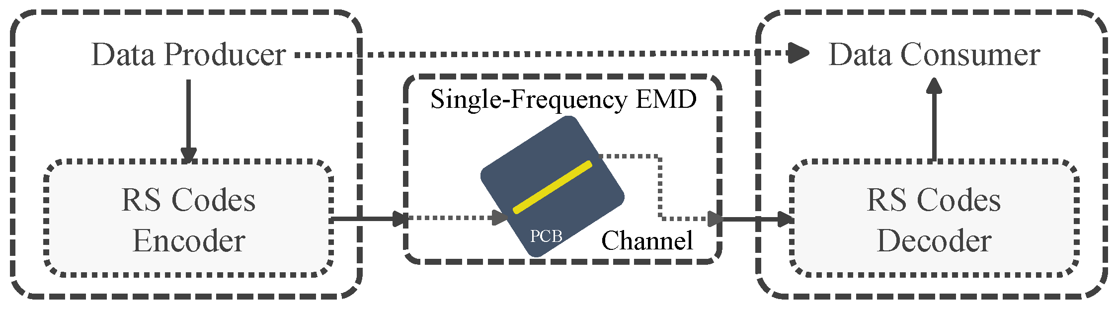
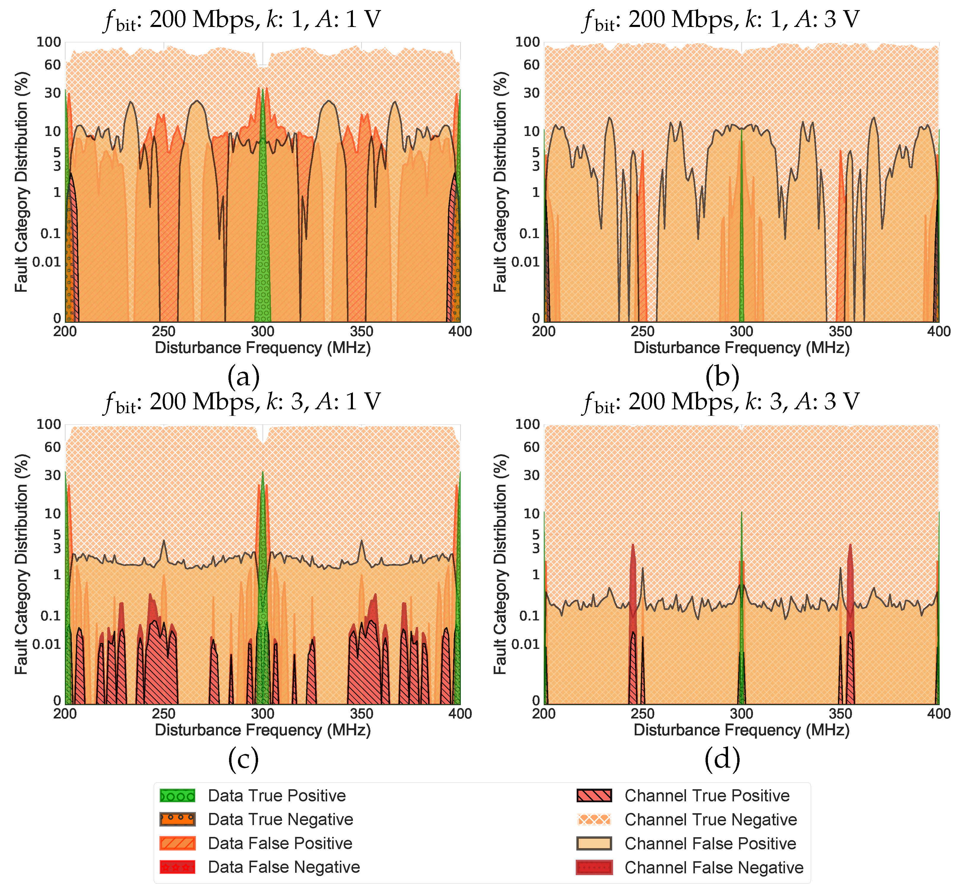
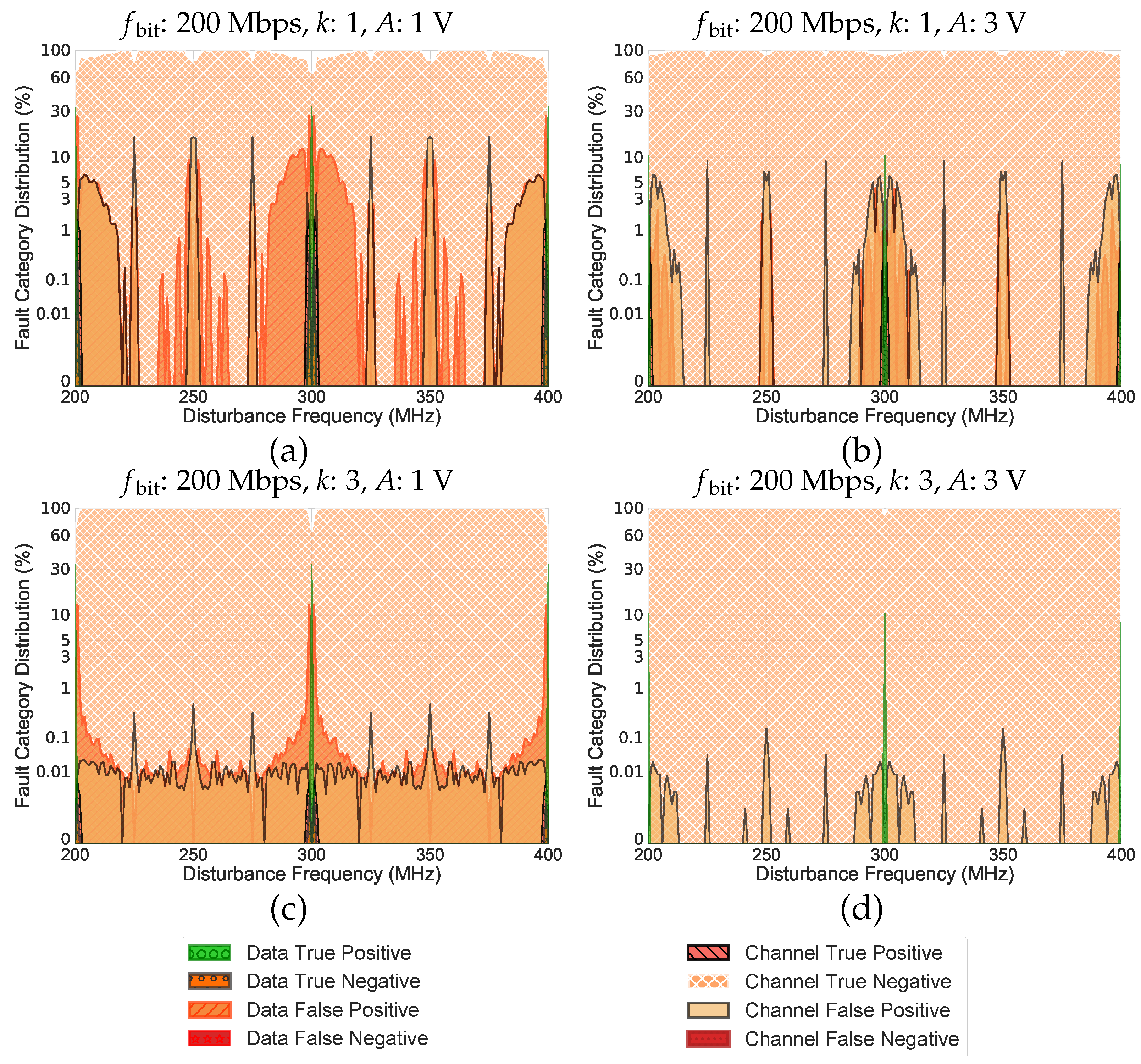
  • Is the data in control or the channel in control?
    Possible Answers: Data or Channel
    To tackle this question, determining the impacts of the disturbances on the outputs of the decoder is required. In this regard, when a disturbance can corrupt at least two valid code words during the transmission in such a way that the output of the decoder for these code words remains the same, then the “Channel” is in control. Otherwise, the “Data” is in control, and it determines the output of the decoder.
In accordance to the different outputs of the aforesaid questions, eight distinct categories are considered which are presented in Table 1. These are labeled with distinct colors (or different shades of a color) throughout the remainder of this paper.
  • Data True Positive (DTP): The data are in control and determine the output, the received output is correct, and the detector outcome is also correct. This is the best scenario. In such a case, the syndrome is zero, which indicates that the code word has not been affected by the disturbance. Accordingly, it shows that the channel is in a good health, and there is no immediate indication that the subsequent transmitted data would be wrong. This is the normal behavior and is labeled in green.
  • Data True Negative (DTN): The data are in control and determine the output, and the received output is incorrect, even though the detector outcome is correct. In this case, the syndrome is nonzero, which indicates that the code word has been affected by the disturbance, and the RS Codes’ detector was able to detect the errors. Three possible scenarios could result in this category. First, when the number of the detected errors is in the RS Codes’ correcting capability, RS Codes miscorrect the corrupted data. In general, in case of a detection, the RS Codes choose a valid code word with the minimum symbol distance (i.e., number of symbol-wise differences between two code words) to the corrupted code word. In some cases, due to the high level of data corruption, the code word turns into another code word that has a minimum symbol distance to a valid code word but not the expected one, and RS Codes mistakenly choose that as the output. Accordingly, this results in a true negative.
    Second, when the number of the detected errors is beyond the RS Codes’ correcting capability, RS Codes detect that no correction can be applied.
    Third, when the number of errors is beyond the RS Codes’ correcting capability, RS Codes falsely assume it is within their capability. Despite this false assumption, RS Codes could not produce any output. In such a case, the code word becomes corrupted, but in a way that there are more than one valid code word with the same minimum symbol distance to the corrupted code word. As a result, this leads to an uncertainty on providing the output, and in the case of RS Codes, uncertainty results in no output.
    It should be noted that, in the second and third scenarios, RS Codes can be designed in such a way to stop the transmission and switch the system to a minimum-risk state. Nevertheless, in all scenarios, the system receives warnings that are desired. This category is labeled in a shade of orange.
  • Data False Positive (DFP): The data are in control and determine the output, and the received output is correct albeit the detector outcome is incorrect. In such a scenario, although the received output is correct, the syndrome is nonzero, which indicates that the code word has been affected by the disturbance. This could happen when RS Codes detect that something went wrong during the transmission and correct the corrupted data. However, the receiver is unable to determine if the correction is valid and the system receives a warning. Based on the initiated assumption, in the case of a positive output, no detection should happen. Furthermore, although the output still depends on the data, it is an indication that the channel’s health might degrade in the future. This category is labeled in a shade of orange.
  • Data False Negative (DFN): The data are in control and determine the output, the received output is incorrect, and the detector outcome is incorrect. In this case, the data producer is either hacked or interfered internally. This is a very dangerous scenario in which the received data will be used without any warning. As a result, the system is unaware that the received data word is wrong, and the system receives no warning. Although this category is detrimental to the overall system safety, it could not occur under the considered fault model as, within this paper, the data producer and the data consumer are assumed to be protected from any EMD or internal hacking. In case this category happens under different environments or setups, it should be labeled in a shade of red.
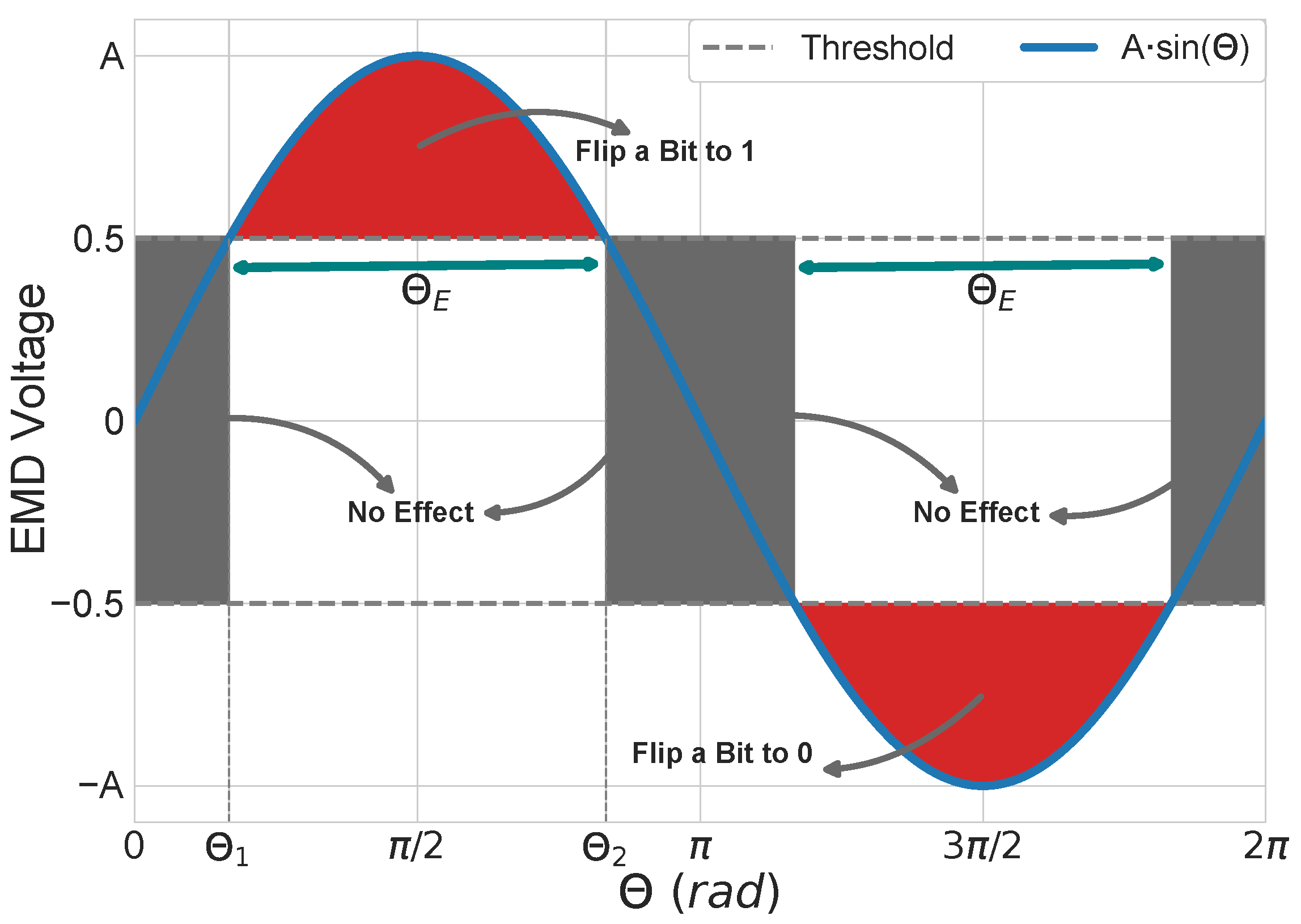
  • Channel True Positive (CTP): The channel is in control and determines the output, the received output is correct, and the detector outcome is also correct. As pointed out, when the channel is in control, the EMDs or any other external factor enforce a logical ‘1’ or ‘0’, regardless of what has been transmitted by the data producer. Accordingly, if the data producer sends a ‘1’ (or ‘0’) while the channel enforces a ‘1’ (or ‘0’), and no detection is occurred by the detector, then a true positive would happen. In other words, CTP happens when the data producer sends a same value as the enforced value by the channel. This indicates a pure luck (i.e., 50% chance to end up as a logical ‘1’ or ‘0’) since if the data producer would have sent a ‘0’ instead and the detector did not detect it, then it would have ended up as a false negative. Therefore, this category must be considered as dangerous as a false negative. Correspondingly, it is labeled in a shade of red.
  • Channel True Negative (CTN): The channel is in control and determines the output, and the received output is incorrect, even though the detector outcome is correct. This category is triggered by the same scenarios indicated for DTN. Furthermore, similar to DTN, the system receives warning which is desired. This category is labeled in a distinct shade of orange;
  • Channel False Positive (CFP): The channel is in control and determines the output, and the received output is correct albeit the detector outcome is incorrect. This category is triggered by the same scenarios stated for DFP, but in these scenarios, the channel is in control. As a result, it reduces the safety of the system. Since the system receives a warning in these scenarios, this category is also labeled in a shade of orange.
  • Channel False Negative (CFN): The channel is in control and determines the output, the received output is incorrect, and the detector outcome is incorrect. This is a very dangerous scenario, since the channel turns the input data into other valid data, and RS Codes assume that all is right (i.e., the calculated syndrome is zero). In such a case, the system is unaware that the received data word is incorrect and, thus, no countermeasures can be taken. Consequently, this undetected category could result in critical failures. Accordingly, this category is considered detrimental to the overall system safety and is, therefore, labeled in a shade of red.
Note that based upon the initial assumption, both data producer and consumer are protected from EMD or any internal hacking. Thus, all categories except DFN could happen within this paper [20]. Accordingly, an important focus of this paper is to study how RS Codes behave under single-frequency EMD, specifically when no warning is given (i.e., CFN), which could result in catastrophic failures, and when the output ends up being correct by an equal chance (i.e., CTP).

4. Reed–Solomon Codes Effectiveness against Single-Frequency EMD

With regard to the implementation, the Python-based RS Codes library provided by [22] is used within this paper. Furthermore, all simulations were carried out based on the parameters specified in Table 2 and the experimental setup that was previously used in [20]. The conceptual overview of this experimental setup is shown in Figure 1. In addition, for the sake of clarity, a simulation example is provided in Appendix A. As shown in Table 2, there are two groups of simulation parameters. In ‘G1’, the length of data words is one symbol, and the generated code words use the maximum Hamming distance as well as the maximum correction capability. On the other hand, the length of data words in ‘G2’ is three symbols, but the generated code words have smaller Hamming distance and correction capability.
Using the aforesaid experimental setup, several graphs were generated of which the most important ones are provided here. Furthermore, due to the periodic behavior of the applied single-frequency interferences, only one period is represented in all graphs.

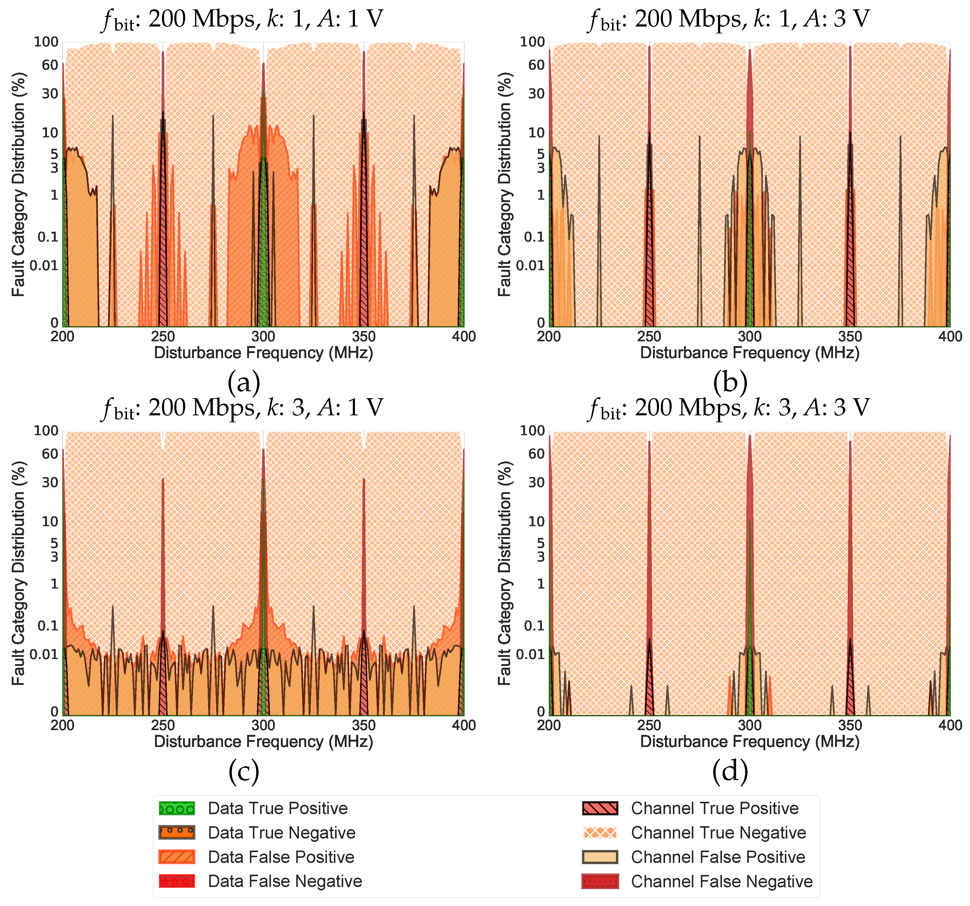
4.1. Peaks of the Undetected Corrupted Data

Figure 2 and Figure 3 depict the fault category distribution of RS Codes under the considered setup for the symbol sizes of 3 and 4, respectively.
Figure 2a,b and Figure 3a,b show this distribution for a message length of 1 symbol (i.e., k = 1 ), while Figure 2c,d and Figure 3c,d, under the same setup, represent the fault category distribution for a message length of three symbols (i.e., k = 3 ). As can be seen in Figure 2 and Figure 3, there are sudden increases in CFN and CTP at specific disturbance frequencies ( f EMD ). These frequencies are dependent on the symbol size (r) and the bit-rate ( f bit ), as shown in Equation (2).
f UCD = j r · f bit , j N + ,
Based on the generated dictionary, we know that there are two types of CFN/CTP that could be generated due to the EMD effect: CFN/CTP triggered by one-symbol-value code words (i.e., all symbols in a code word are identical) and CFN/CTP triggered by multi-symbol-value code words (i.e., all other code words except the one-symbol-value code words). Based on the specified setup parameters, code words with multi-symbol values are only generated when k > 1 (i.e., Figure 2c). In this case, in addition to one-symbol-value code words, the generated dictionary contains multi-symbol-value code words as well. Moreover, it is found that, owing to the periodicity of the single-frequency disturbances, all CFN and CTP at these peaks/frequencies are one-symbol-value code words. This is due to the fact that, at the mentioned EMD frequencies, sampling positions of all symbols are identical, which would alter them equally.
The areas in a single-frequency disturbance that lead to a bit-flip are demonstrated in Figure 4. As can be observed, the part of the sine wave (i.e., single-frequency disturbance) greater than or equal to 0.5 V is responsible for turning a bit to 1, while the negative part, where it is less than or equal to −0.5 V, is responsible for turning a bit to 0. The middle area has no effect as it cannot create a bit-flip. Equation (3) calculates the domain ( Θ E ), which leads to half of all possible bit-flips, i.e., only the part where a bit turns to 1 or only the part where a bit turns to 0.
Θ E = Θ 2 Θ 1 and Θ 1 = π Θ 2 Θ E = π · Θ 1 , A · sin ( Θ 1 ) = 0.5 Θ 1 = a r c s i n ( 0.5 A ) , Θ E = π 2 · a r c s i n ( 0.5 A ) = 2 · a r c c o s ( 0.5 A ) ,
Using the information from Figure 4 and having the number of valid code words in the dictionary (i.e., q m k = 2 m k ), the ratios of DTP, CTP, and CFN at the harmonics of the disturbance frequency (i.e., f EMD = j · f bit , j N + ) can be calculated by Equations (4)–(6).
DTP ( % ) = ( 2 π 2 · Θ E ) 2 π · 100 ,
CTP ( % ) = 2 · 1 2 m k · Θ E 2 π ,
CFN ( % ) = ( [ 2 m k 2 2 m k · 2 · Θ E 2 π ] + [ 2 · ( 1 2 m k · Θ E 2 π ) ] ) · 100 ,
As can be seen in Figure 4, the middle area of the graph has no effect, which, accordingly, results in a DTP. The angle that leads to this category is simply obtained by subtracting the areas responsible for generating bit-flips (i.e., Θ E ) from the period of the single-frequency disturbance (i.e., 2 π ). Subsequently, the DTP ratio can be calculated with Equation (4). Please note that this ratio only depends on the EMD voltage, and it is independent of the symbol size value (m) and the data word length (k).
Additionally, the CTP ratio can be determined via Equation (5). There are only two possible scenarios that could lead to a CTP at harmonics of the disturbance frequency, which only happen within the range of Θ E . Either when the channel enforces a logical ‘1’ and the transmitted bit-string is all ‘1’ (i.e., all bits of all symbols are ‘1’), or when the channel enforces a logical ‘0’, and the transmitted bit-string is also all ‘0’.
Furthermore, Equation (6) can be used to calculate the ratio of CFN. The first part of Equation (6) calculates the CFN ratio for all code words except all 0’s and all 1’s code words, leaving ( 2 m k 2 ) / 2 m k code words. The second part, however, only calculates this ratio for all 0’s and all 1’s code words. Note that the second part of Equation (6) uses half of the calculated angle since only one side of the sine wave (i.e., single-frequency disturbance) results in a bit-flip for each code word. In other words, the only possible CFN event at harmonics of the bit-frequency for the all 0’s code word is all 1’s. Likewise, the only possible CFN event for the all 1’s code word is all 0’s. Nevertheless, other code words can turn into both all 0’s and all 1’s code words at the harmonics of the disturbance frequency, and the factor of 2 · Θ E indicates this fact. Equation (7) provides an overview on the occurrence probability of the mentioned CFN areas at EMD harmonics.
P t u r n t o a l l 0 s / 1 s = 2 · Θ E 2 π all code words except all 1 s and all 0 s , P t u r n t o a l l 0 s = Θ E 2 π all 1 s code word , P t u r n t o a l l 1 s = Θ E 2 π all 0 s code word ,
Accordingly, the purple points in Figure 5a–c validates the obtained results at harmonics (i.e., DTP, CTP, and CFN ratios at 200 MHz and 400 MHz in Figure 2 and Figure 3) by representing the aforementioned ratios for different amplitudes based on Equations (4)–(6).

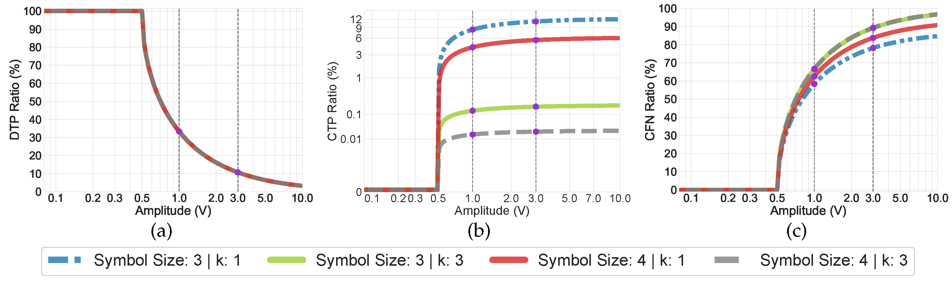
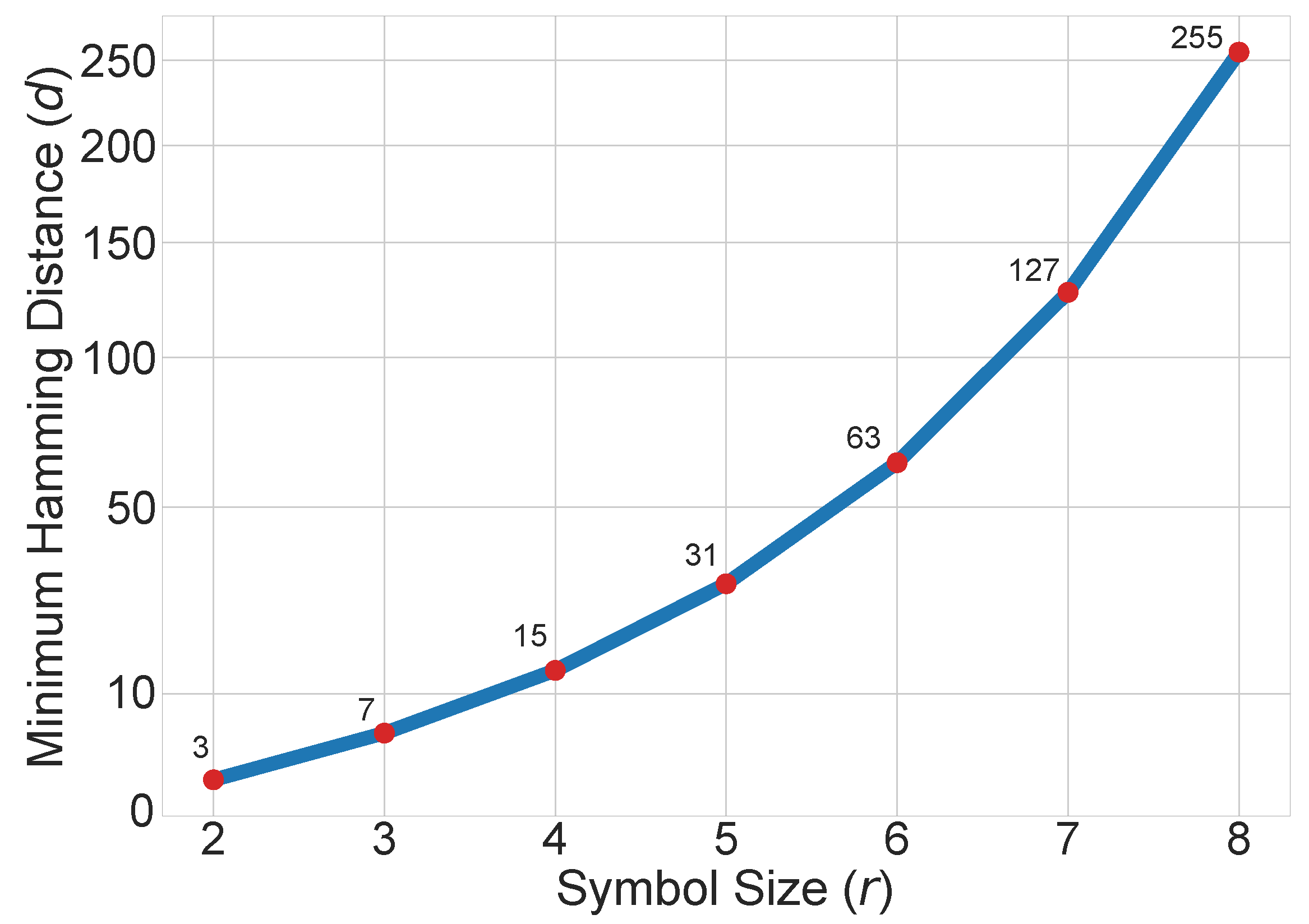
4.2. Impact of the Symbol Size

As evidenced in Figure 3, increasing the symbol size results in more CTP and CFN peaks. Equation (2) indicates that, in addition to CTP and CFN peaks at harmonics, there are always r 1 CTP and CFN peaks between two harmonics of f bit . Take the symbol size of 4 as an example, i.e., Figure 3. In this case, the first groups of disturbance frequencies, at which a lot of CTP and CFN occur, are in the range of 5 / 4 , 6 / 4 , and 7 / 4 of the rate f bit 200 MHz (i.e., 250 MHz, 300 MHz, and 350 MHz). The second groups are the disturbance frequencies in the range of the harmonics of the f bit (i.e., 200 MHz and 400 MHz), when j is a multiple of m (i.e., symbol size) in Equation (2). The former results in all possible code words with one-symbol value except all 0’s and all 1’s code words (i.e., 1 symbol-value 2 m 1 ), e.g., [ 0110 , 0110 , 0110 , , 0110 , 0110 , 0110 ] ; and the latter only yields all 0’s and all 1’s code words (i.e., symbol-value = 0 or 2 m 1 ), e.g., [ 1111 , 1111 , 1111 , , 1111 , 1111 , 1111 ] . Note that, in both cases, all symbols of a code word turn into a single value. Moreover, this altered code word is considered valid based on the initially generated dictionary.
Although smaller symbol sizes have less CTP and CFN peaks, they contain a wider frequency range (see, e.g., Figure 2). This is because of the smaller Hamming distance that makes the code words more susceptible to turn into another valid code word. In other words, smaller number of bit-flips is required to transform it into another valid code word. Thus, more frequencies around each peak can generate CTP or CFN. It is worth noting that all the corrupted code words generated by the frequencies around each peak and the peak itself are identical.
In mathematical terms, the minimum Hamming distance among generated code words of the RS Codes dictionary is n k + 1 . Thus, at least n k + 2 bit-flips are required to transform any code word to another valid code word.
As shown in Figure 6, increasing the symbol size by keeping k constant (i.e., k = 1 ) increases the minimum Hamming distance (i.e., n k + 1 = n = 2 m 1 ) as well as the imposed overhead (i.e., n = 2 m 1 ). This also indicates an increase in the required number of bit-flips to generate a valid code word. However, due to the repetitive behavior of continuous EMD wave, the probabilities of generating one-symbol-value code words are higher. This is the reason why increasing the symbol size is also not in our favor and causes more peaks of CTP and CFN.
It is worth noting that an increase in the symbol size also decreases the ratios of DTP (green category) and CFP (i.e., the category in a shade of orange) and also increases the ratio of CTN (i.e., the category in shade on orange). This indicates that, for larger symbol sizes, RS Codes have a stronger detection capability than correction capability. RS Codes are designed to deal with bursts of errors. However, continuous wave EMDs occur in a periodic pattern, and this is the reason why data corruption is more intense for codes with greater block length. To this end, these setups lead to very low ratios of DTP (green category).

4.3. Impact of the Message Length

Increasing the message length has no effect on the number of mentioned CTP and CFN peaks and the peak frequencies in which happen. However, an increased message length decreases the minimum Hamming distance among code words. This means a smaller number of bit-flips would be required to generate a CTP or CFN. Accordingly, due to the smaller Hamming distance, CTP and CFN peaks in Figure 2 are wider in comparison with Figure 3. In these cases, the message length increased to three symbols, which in turn decreased the minimum Hamming distance among code words.
In case that k = 3 (i.e, Figure 2c), there are other CTPs and CFNs in addition to the mentioned peaks. These peaks are caused by multi-symbol-value code words. Compared to the required number of bit-flips to generate valid one-symbol-value code words, which are responsible for the main peaks, smaller numbers of bit-flips are needed to generate valid multi-symbol-value code words. Note that more intense disturbances (i.e., greater induced voltages) are able to push more data points beyond the specified threshold, and they generate bit-flips in great numbers (i.e., tend to generate one-symbol-value code words).
As can be seen in Figure 3, there is no CTPs or CFNs with a multi-symbol value for the symbol size of 4 under the considered electromagnetic variables. This is due to the fact that the required number of bit-flips in this case (i.e., 16 bit-flips) is greater than the required number of bit-flips for the symbol size of 3 (i.e., 6 bit-flips).

4.4. Impact of the EMD Amplitude

The amplitude of the induced voltage has a noticeable effect on the CTP and CFN ratios at the mentioned peak frequency, i.e., f UCD in Equation (2). This effect is clearly observable in Figure 7 in which the increasing trends of CFN ratios for symbol size of 4 at f UCD (i.e., 250 MHz, 300 MHz, 350 MHz, and harmonics) have been shown.
The underlying reasons for this are the disturbance severity and the dependency demonstrated by Equation (2). In other terms, more intense disturbances are capable of pushing more data points (i.e., voltages) below or above the specified threshold, which can lead to repetitive patterns in code words’ elements.

5. EMD-Resilient Reed–Solomon Codes

Based upon the observations in Section 4, it can be concluded that the main vulnerability of RS Codes to CTP and CFN is due to the occurrence of one-symbol-value code words. Mitigating these specific type of vulnerability would significantly improve the EM-resiliency of RS Codes. Although one-symbol-value CTP and CFN cannot be detected by RS Codes, which have potentially detrimental impacts on safety critical applications, it is possible to detect this specific category at a lower layer [21]. In what follows, an effective layer was proposed to address this specific vulnerability.

5.1. Single Symbol Inversion

In mathematical terms, the minimum Hamming distance among valid code words is n k + 1 , thus inverting any number of bits less than or equal to the minimum Hamming distance in all code words cannot generate a valid one. However, it would break the repetitiveness in code words with one-symbol-value. Furthermore, it guarantees that valid multi-symbol-value code words never turn into one-symbol-value code words. As a result, the initial generated dictionary by primitive RS Codes, which contains one-symbol-value code words, is no longer valid at the inversion layer, and receiving any code word from that dictionary at the consumer side is not valid anymore. Hence, by checking this condition at the consumer side, it is possible to detect CTP and CFN. Accordingly, in our proposed algorithm, one symbol of a code word is required to obtain an inverted one. Note that inverting one symbol does not violate the mentioned criteria (i.e., m n k + 1 ) since the size of one symbol (i.e., m) is always less than the minimum Hamming distance (i.e., n k + 1 ). An overview of the Single Symbol Inversion (SSI) mechanism is provided in Equation (8).
S S I [ D 1 , , D i , P 1 , P 2 , , P j ] = [ D 1 , , D i , P 1 ¯ , P 2 , , P j ] ,
As indicated in Equation (8), the first symbol of the parity ( P 1 ) is inverted in this paper. However, it should be noted that any symbol locations can be considered for the inversion as the sole purpose of this mechanism is to break the repetitive nature of code word’s symbols, and the difference in the final outcomes would not be significant.
In the case that the mentioned condition is not encountered, the applied changes should be reverted, followed by transmitting the code word to the RS Codes’ decoder. The block diagram of the proposed approach is shown in Figure 8.
As can be seen, instead of using two layers in the communication channel, three layers are used to overcome the mentioned vulnerability. The SSI encoder at Layer 2 is responsible for applying the inversion to break the repetitiveness in the generated code words by RS Codes encoder at layer 3 and generates a new dictionary. In this new dictionary, one-symbol-value code words, which are mainly responsible for the CTP and CFN at layer 3, are no longer valid, and they can easily be detected by the SSI decoder at layer 2. Accordingly, CTP and CFN at layer 3 convert to CTN at layer 2, i.e., the SSI decoder produces no output by design, which is considered as a “Negative” based on the initial assumption, followed by a “True” detection at the SSI decoder. Nevertheless, although other code words can pass through this layer without any protection regardless of their status, they will be handled by the RS Codes decoder at layer 3. At this layer, the RS Codes decoder performs its normal operation on the received code words. In other words, layer 2 fills the safety gap in the communication channel by addressing the vulnerability of layer 3, i.e., detecting corrupted code words that are not detectable by RS Codes decoder. Accordingly, this combination of layers guarantees a safer operation in the considered communication network.

5.2. Overall Performance of the Proposed Layer

Figure 9 and Figure 10 represent the categorized results of the proposed multi-layer structure on the overall performance of the channel. As can be seen, when k = 1 (i.e., Figure 9a,b and Figure 10a,b), the rate of CFN dropped to an absolute zero under the considered electromagnetic variables, as was the objective of this paper. In addition, the rate of CTP dropped significantly in these cases. Furthermore, a large drop in CTP and CFN ratios is noticeable when k = 3 (i.e., Figure 9c,d and Figure 10c,d). In this case, the majority of CFN and CTP caused by one-symbol-value code words at the frequencies of f CFN are eliminated and turned into a detectable category (i.e., CTN) for the inversion layer. The remaining CTP and CFN at other frequencies are caused by multi-symbol-value code words. Nevertheless, although due to the inversion mechanism, more multi-symbol value CTPs and CFNs appear in Figure 9c compared to Figure 2c, and the overall resilience against CTP and CFN actually increased as all major spikes caused by one-symbol-value code words are eliminated.
Figure 10 show that the proposed inversion mechanism has provided a better EM-resiliency for the symbol size of 4. This reflects the fact that the greater Hamming distance requires more bit-flips to generate a one-symbol-value code word, which in this case provides a better resiliency against single-frequency EMDs. In other words, using the proposed mechanism, symbol sizes greater than 3 would provide more resilient codes as they have greater Hamming distances (remember the relation which has been shown in Figure 6).
In addition, Table 3 provides a comparison between the original RS Codes and the proposed multi-layer structure. For each category, all correspondent data are averaged out over the considered frequency range and are presented in percentage (%). As evidenced, except the three categories of CTN, CTP, and CFN, the difference among other categories of a same setup is not substantial. This is exactly in line with the objective of this paper. CTP and CFN are the only two categories that are determinantal to the overall safety of the system. The proposed approach was able to catch most of the CTP and CFN instances and flagged them as CTN while imposing minimal impacts on the other categories. Note that these values are indicated in bold in Table 3.
Nevertheless, as can be seen in Figure 9 and Figure 10, there are still several incidents of one-symbol-value CTP around some frequencies of f UCD (e.g., around 200 MHz and 400 MHz in Figure 9d, as well as around 200 MHz, 300 MHz, and 400 MHz in Figure 10a). These scenarios could happen when the channel is in control but in a way that it does not control all symbols of a code word. Accordingly, the inverted symbol could remain untouched during the transmission. As a result, the data consumer receives a code word that is not within the initial generated dictionary; therefore, it can pass through the inversion layer without detection. Thereby, after reverting the applied changes, the received code word could turn into a valid code word for RS Codes, which results in a CTP or CFN.
In general, it is possible to determine which code words can end up as a one-symbol-value CTP or CFN. Based on RS Codes parameters, the total number of possible corrupted code words at the consumer side is ( q m ) n . Given that, the number of possible code words that can turn into one-symbol-value CFN while reverting changes is q m 1 , if the transmitted code word is a one-symbol-value code word and is q m (i.e., the total number of one-symbol-value code words), and if the transmitted code word being a multi-symbol-value code word. Similarly, the number of possible code words that can turn into one-symbol-value CTP while reverting changes is 1, which only happens when the transmitted code word is the same one-symbol-value code word as the input.
For instance, Table 4 shows the possible cases that can turn into a one-symbol-value CFN or CTP when r = 3 , k = 3 , and the transmitted code word is [ 2 , 2 , 2 , 2 , 2 , 2 , 2 ] . As can be seen, seven possible cases (i.e., q m 1 ) lead to CFN, and one case leads to CTP. Note that this behavior holds for all other one-symbol-value code words regardless of their initiated setup parameters.
This indicates the limitation of the proposed layer as it only works flawlessly when the channel controls all symbols of a code word in a same manner, and in case of a partial control, there are always some edge cases that could bypass the inversion layer. Nevertheless, despite the mentioned limitations, the inversion layer still has a great capability to improve the resiliency of RS Codes substantially against single-frequency EMD by eliminating the major CFN and CTP spikes in the graphs.
Another limitation of the proposed approach is dependency to a look-up table at the consumer side of the inversion layer. For bigger message lengths, this look-up table is also becoming bigger, which could create a lot of challenges for implementing this technique in embedded systems with small memory.
Correspondingly, the obtained results indicate that k = 1 provides a significantly higher resiliency as the occurrence probability of CFN and CTP caused by multi-symbol-value code words is zero. Moreover, according to the results, using k = 1 combined with any symbol sizes (m) greater than 3 would provide even higher resiliency due to the greater Hamming distance. In the case of k = 1 , a smaller look-up table becomes generated, which significantly alleviates the mentioned limitation. However, for m > 3 , the block length also increases, which imposes more overhead. From the safety perspective, the acceptance of this trade-off totally depends on the application.

6. Conclusions

This paper studied the effectiveness of primitive RS Codes against single-frequency EMD. It was shown that there is a special relation among RS Codes’ symbol size, bit-rate frequency, and disturbance frequency. Due to this relation, EMD tends to induce voltages at the harmonics and several other ratios of the bit-rate frequency in such a way that turns any code words into one-symbol-value code words. These code words are valid in accordance with the initial generated dictionary, and they are responsible for most undetected corrupted incidents. It is found that, in the worse-case scenarios, the rate of undetected corrupted incidents could increase to values above 80%.
Based upon these findings, a multi-layer communication structure, as suggested in [21], on the basis of symbol inversion was proposed to arm the communication network against this specific type of disturbance. This study demonstrated that the proposed multi-layer structure alleviates the concern about the generated ratios from the aforesaid setup parameters. At the new proposed layer, the inversion mechanism breaks the repetitiveness in each code word by generating a new dictionary in which one-symbol-value code words are no longer valid. Accordingly, they can easily be detected prior transmission to the RS Codes’ decoder. The performance of this mechanism was assessed with the aid of our in-house simulation framework. It is found that the proposed inversion-based layer is capable of reducing the ratio of undetected corrupted data considerably.
Simulations showed that, at the frequencies of concern, the new proposed approach could decrease the ratio of undetected corrupted data to values close to 0. Furthermore, it is shown that certain setups could even provide more resiliency towards the single-frequency EMD. This is when the message length is limited to one symbol and the symbol size is greater than 3, by which a higher hamming distance is achievable. In this regard, this approach is suited as an extra layer of protection to limit the impact of single-frequency EMD on RS Codes in safety-critical or mission-critical applications.
In the future studies, a more efficient approach with a lower overhead compared to the proposed approach will be investigated. In addition, in addition to alleviating the current limitation (i.e., dependency to look-up tables at the consumer side of the inversion-layer), more complex EM environments will be considered to examine the EM-resilience of RS Codes against undetected corrupted data.

Author Contributions

Conceptualization, J.B., D.P. and P.M.; methodology, P.M.; software, P.M.; validation, D.V. and T.C.; formal analysis, J.V. and D.V.; investigation, P.M.; resources, J.B.; data curation, P.M.; writing—original draft preparation, P.M.; writing—review and editing, all authors; visualization, P.M.; supervision, J.B., D.V. and D.P.; project administration, D.P. and J.B.; funding acquisition, D.P. and J.B. All authors have read and agreed to the published version of the manuscript.

Funding

The research leading to these results has received funding from the European Union’s Horizon 2020 Research and Innovation programme under the Marie Skłodowska-Curie Grant Agreement No 812.790 (MSCA-ETN PETER). This publication reflects only the authors’ view, exempting the European Union from any liability. Project website: http://etn-peter.eu/ (accessed on 1 April 2019).

Conflicts of Interest

The authors declare no conflict of interest.

Appendix A. Simulation Example

This section provides an example of an entire cycle of the simulation setup for clarity. As described in Table A1, several input data words were considered. Based on the chosen symbol size (i.e., 3), these data words are then encoded to their corresponding code words. After converting them into their binary formats (e.g., [ 2 , 2 , 2 , 2 , 2 , 2 , 2 ] converts to [ 010 , 010 , 010 , 010 , 010 , 010 , 010 ] ), the code words convert to voltages using the Non-Return to Zero Level encoding, i.e, a logical ‘0’ is converted to 0 V and a logical ‘1’ to 1 V.
Table A1. Examples to demonstrate the impact of EMD on the data during the transmission.
#AmplitudefEMDInputTransmittedReceivedPossible OutputOutputCategory
(V)(MHz)Data WordCode WordCode WordCode Word(s)Data Word
11300 [ 2 ] [ 2 , 2 , 2 , 2 , 2 , 2 , 2 ] [ 2 , 2 , 2 , 2 , 2 , 2 , 2 ] [ 2 , 2 , 2 , 2 , 2 , 2 , 2 ] [ 2 ] DTP
20.6280 [ 0 ] [ 0 , 0 , 0 , 0 , 0 , 0 , 0 ] [ 1 ̲ , 0 , 2 ̲ , 0 , 4 ̲ , 1 ̲ , 0 ] [ 0 , 0 , 0 , 0 , 0 , 0 , 0 ] [ 0 ] DTN
31204 [ 6 ] [ 6 , 6 , 6 , 6 , 6 , 6 , 6 ] [ 7 ̲ , 7 ̲ , 6 , 6 , 6 , 6 , 0 ̲ ] [ 6 , 6 , 6 , 6 , 6 , 6 , 6 ] [ 6 ] DFP
41200 [ 7 ] [ 7 , 7 , 7 , 7 , 7 , 7 , 7 ] [ 7 , 7 , 7 , 7 , 7 , 7 , 7 ] [ 7 , 7 , 7 , 7 , 7 , 7 , 7 ] [ 7 ] CTP
51202 [ 3 ] [ 3 , 3 , 3 , 3 , 3 , 3 , 3 ] [ 7 ̲ , 7 ̲ , 7 ̲ , 7 ̲ , 7 ̲ , 7 ̲ , 3 ] [ 7 , 7 , 7 , 7 , 7 , 7 , 7 ] [ 7 ] CTN
61250 [ 4 ] [ 4 , 4 , 4 , 4 , 4 , 4 , 4 ] [ 4 , 6 ̲ , 3 ̲ , 1 ̲ , 4 , 6 ̲ , 3 ̲ ] [ 3 , 3 , 3 , 3 , 3 , 3 , 3 ] [ 4 , 4 , 4 , 4 , 4 , 4 , 4 ] [ 6 , 6 , 6 , 6 , 6 , 6 , 6 ] NACTN
71204 [ 0 ] [ 0 , 0 , 0 , 0 , 0 , 0 , 0 ] [ 7 ̲ , 7 ̲ , 6 ̲ , 0 , 0 , 0 , 0 ] [ 0 , 0 , 0 , 0 , 0 , 0 , 0 ] [ 0 ] CFP
81200 [ 1 ] [ 1 , 1 , 1 , 1 , 1 , 1 , 1 ] [ 7 ̲ , 7 ̲ , 7 ̲ , 7 ̲ , 7 ̲ , 7 ̲ , 7 ̲ ] [ 7 , 7 , 7 , 7 , 7 , 7 , 7 ] [ 7 ] CFN
In these Example, symbol size = 3, K = 1, phase = 270°, and bit-rate = 200 MHz. Under-bar is used to demonstrate the error positions. Furthermore, differences between the possible output(s) and the received code word are indicated in bold.
The resultant code words then pass through the corrupter where they are exposed to a single-frequency disturbance with a phase of 270 degrees. In cases where the resultant voltages are greater than or equal to the specified threshold (i.e., 0.5 V), they convert to logical ‘1’, and voltages less than 0.5 V are converted to logical ‘0’. Subsequently, the binary code words convert to their decimal formats or symbol-based code words.
For this example, eight different scenarios were selected, which resulted in different categories. For the first three examples, the data are in control, and for the rest, the channel is in control.
As can be seen, in row 1, at a frequency of 300 MHz ( f bit is 200 MHz), the code word is not affected by the EMD; thus, no correction is required (i.e., syndrome = 0), and the output would be the same as the input (i.e., DTP).
In row 2, at a frequency of 280 MHz, although four symbols become corrupted due to EMD, the data are still in control. Accordingly, RS Codes chose the code word with the minimum symbol distance (i.e., 4) to the corrupted code word. Note that other valid code words in the dictionary have a minimum symbol distance of at least five relative to the corrupted code word. Unlike other categories, due to the required conditions for the occurrence of DTN, this category does not occur under most setups, and in case it occurs, the ratio of it is comparatively smaller than other categories. It is found that when the induced voltages have smaller values (e.g., 0.6 V) or a code word has a smaller block length (e.g., for the symbol size of 2), DTN tends to happen more often.
In row 3, at a frequency of 204 MHz, three symbols become corrupted (i.e., at symbols 1, 2, and 7) due to the EMD. However, this number of errors is within the provided RS Codes’ correction capability, and the output will be matched with the input (i.e., DFP).
In row 4, at a frequency of 200 MHz, at the first sight, everything seems correct, but the channel actually is in control and enforces a logical ‘1’ to all transmitted bits. As mentioned earlier, such a scenario happens by pure luck (i.e., CTP), and if any other code words are transmitted under this disturbance, the output would be always the same and the results are in a false negative.
In row 5, at a frequency of 202 MHz, six symbols become corrupted due to the EMD. However, RS Codes falsely assume only one error has occurred as the minimum symbol distance of the received code word to another valid code word (i.e., [ 7 , 7 , 7 , 7 , 7 , 7 , 7 ] ) is 1. As a result, RS Codes choose this code word as the output, which results in miscorrection (i.e., CTN).
Row 6 is similar to row 5, but under the specified disturbance, the transmitted code word becomes corrupted but in a way that there are three valid code words with the same minimum symbol distance (i.e., 5) to the corrupted code word. Consequently, RS Codes fail to produce an output (i.e., CTN).
Row 7 is also similar to row 2 but with the difference that the channel is in control and enforces the values (i.e., CFP).
In row 8, at a frequency of 200 MHz, all symbols become corrupted, which turn the input code word into another valid code word. In this case, although the corrupted code word is incorrect, RS Codes think that nothing has occurred (i.e syndrome = 0), and it sends the input data directly to the output (i.e., CFN). As can be seen in Figure A1, due to the periodicity of the single-frequency EMD, all bits are turned into ‘1’. Correspondingly, all symbols are affected and are turned into the same symbol (i.e., in this case, ‘111’ or 7).
Figure A1. Behavior of one code word under a single-frequency disturbance.
Electronics 11 01292 g0a1

References

  1. Pissoort, D.; Armstrong, K. Why is the IEEE developing a standard on managing risks due to EM disturbances? In Proceedings of the 2016 IEEE International Symposium on Electromagnetic Compatibility (EMC), Ottawa, ON, Canada, 25–29 July 2016; pp. 78–83. [Google Scholar]
  2. Hamming, R.W. Error detecting and error correcting codes. Bell Syst. Tech. J. 1950, 29, 147–160. [Google Scholar] [CrossRef]
  3. Van Waes, J.; Lannoo, J.; Degraeve, A.; Vanoost, D.; Pissoort, D.; Boydens, J. Effectiveness of cyclic redundancy checks under harsh electromagnetic disturbances. In Proceedings of the 2017 International Symposium on Electromagnetic Compatibility-EMC EUROPE, Angers, France, 4–7 September 2017; pp. 1–6. [Google Scholar]
  4. Van Waes, J.; Lannoo, J.; Vankeirsbilck, J.; Degraeve, A.; Peuteman, J.; Vanoost, D.; Pissoort, D.; Boydens, J. Effectiveness of hamming single error correction codes under harsh electromagnetic disturbances. In Proceedings of the 2018 International Symposium on Electromagnetic Compatibility (EMC EUROPE), Amsterdam, The Netherlands, 27–30 August 2018; pp. 271–276. [Google Scholar]
  5. Van Waes, J.; Vankeirsbilck, J.; Lannoo, J.; Pissoort, D.; Boydens, J. Effectiveness of data triplication in harsh electromagnetic environments. In Proceedings of the 2018 International Symposium on Electromagnetic Compatibility (EMC EUROPE), Amsterdam, The Netherlands, 27–30 August 2018; pp. 266–270. [Google Scholar]
  6. Van Waes, J.; Vanoost, D.; Vankeirsbilck, J.; Lannoo, J.; Pissoort, D.; Boydens, J. Resilience of Error Correction Codes against Harsh Electromagnetic Disturbances: Fault Mechanisms. IEEE Trans. Electromagn. Compat. 2020, 62, 1017–1027. [Google Scholar] [CrossRef]
  7. Van Waes, J.; Vanoost, D.; Vankeirsbilck, J.; Lannoo, J.; Pissoort, D.; Boydens, J. Resilience of Error Correction Codes Against Harsh Electromagnetic Disturbances: Fault Elimination for Triplication-Based Error Correction Codes. IEEE Trans. Electromagn. Compat. 2020, 62, 1929–1938. [Google Scholar] [CrossRef]
  8. Reed, I.S.; Solomon, G. Polynomial codes over certain finite fields. J. Soc. Ind. Appl. Math. 1960, 8, 300–304. [Google Scholar] [CrossRef]
  9. Al-Barrak, A.; Al-Sherbaz, A.; Kanakis, T.; Crockett, R. Enhancing BER performance limit of BCH and RS codes using multipath diversity. Computers 2017, 6, 21. [Google Scholar] [CrossRef] [Green Version]
  10. An, X.; Liang, Y.; Zhang, W. High-Efficient Reed-Solomon Decoder Based on Deep Learning. In Proceedings of the 2020 IEEE International Symposium on Circuits and Systems (ISCAS), Seville, Spain, 12–14 October 2020; pp. 1–5. [Google Scholar]
  11. Zhang, W.; Zou, S.; Liu, Y. Iterative soft decoding of reed-solomon codes based on deep learning. IEEE Commun. Lett. 2020, 24, 1991–1994. [Google Scholar] [CrossRef]
  12. Xing, J.; Chen, L.; Bossert, M. Low-Complexity Chase Decoding of Reed-Solomon Codes Using Module. IEEE Trans. Commun. 2020, 68, 6012–6022. [Google Scholar] [CrossRef]
  13. Wang, H.; Zhang, W.; Chang, Y.; Gao, J.; Liu, Y. Low-Complexity Chase Decoding of Reed–Solomon Codes Using Channel Evaluation. Entropy 2022, 24, 424. [Google Scholar] [CrossRef]
  14. Kumar, S.; Gupta, R. Bit error rate analysis of Reed-Solomon code for efficient communication system. Int. J. Comput. Appl. Technol. 2011, 30, 11–15. [Google Scholar]
  15. Mahajan, S.; Singh, G. Reed-Solomon code performance for M-ary modulation over AWGN channel. Int. J. Eng. Res. Technol. (IJEST) 2011, 3, 3739–3745. [Google Scholar]
  16. Korrapati, V.; Prasad, M.; Reddy, D.V.; Tej, G.A. A Study on performance evaluation of Reed Solomon Codes through an AWGN Channel model for an efficient Communication System. Int. J. Eng. Trends Technol. 2013, 4, 1038–1041. [Google Scholar]
  17. Nandaniya, J.S.; Kalani, N.B.; Kulkarni, G. Comparative analysis of different channel coding techniques. Int. J. Comput. Netw. Commun. (IJCNWC) 2014, 4, 84–89. [Google Scholar]
  18. Geisel, W.A. Tutorial on Reed-Solomon Error Correction Coding; National Aeronautics and Space Administration, Lyndon B. Johnson Space Center: Houston, TX, USA, 1990; Volume 102162.
  19. Peterson, W.W.; Peterson, W.; Weldon, E.J.; Weldon, E.J. Error-Correcting Codes; MIT Press: Cambridge, MA, USA, 1972. [Google Scholar]
  20. Memar, P.; Vankeirsbilck, J.; Vanoost, D.; Holvoet, T.; Boydens, J. Resilience of Reed-Solomon Codes Against Harsh Electromagnetic Disturbances: Influence of Over-Voltage Detection. In Proceedings of the 2021 IEEE International Joint EMC/SI/PI and EMC Europe Symposium, Raleigh, NC, USA, 26 July–13 August 2021; pp. 868–873. [Google Scholar] [CrossRef]
  21. Claeys, T.; Tirmizi, H.; Habib, H.; Vanoost, D.; Vandenbosch, G.A.; Pissoort, D. A system’s perspective on the use of EMI detection and correction methods in safety critical systems. In Proceedings of the 2021 IEEE International Joint EMC/SI/PI and EMC Europe Symposium, Raleigh, NC, USA, 26 July–13 August 2021; pp. 905–910. [Google Scholar]
  22. Filiba, T.; Larroque, S.K. Universal Errors-and-Erasures Reed-Solomon Codec: ReedSolo. 2020. Available online: https://github.com/tomerfiliba/reedsolomon (accessed on 31 January 2021).
Figure 1. Conceptual overview of the experimental setup.
Electronics 11 01292 g001
Figure 2. Reed–Solomon Codes Effectiveness under single-frequency electromagnetic disturbances for the symbol size of 3.
Electronics 11 01292 g002
Figure 3. Reed–Solomon Codes Effectiveness under single-frequency electromagnetic disturbances for the symbol size of 4.
Electronics 11 01292 g003
Figure 4. Effectiveness of each area in a single-frequency disturbance with regard to bit-flips.
Electronics 11 01292 g004
Figure 5. Theoretically calculated DTP, CTP, and CFN ratios at harmonics of the disturbance frequency when fbit is 200 Mbps.
Electronics 11 01292 g005
Figure 6. Symbol size effect on the minimum hamming distance while k = 1 .
Electronics 11 01292 g006
Figure 7. Increasing trend of CFN ratio at specific fractions of the disturbance frequency harmonics.
Electronics 11 01292 g007
Figure 8. Conceptual overview of the proposed multi-layer communication structure.
Electronics 11 01292 g008
Figure 9. The impact of the inversion layer on the EM-resiliency of RSCodes for a symbol size of 3.
Electronics 11 01292 g009
Figure 10. The impact of the inversion layer on the EM-resiliency of RSCodes for a symbol size of 4.
Electronics 11 01292 g010
Table 1. An overview of the considered categories.
CategoryChannel StatusData StatusDetector StatusLabel
Data True Positive (DTP)Data In ControlUncorruptedNo Warning Electronics 11 01292 i001
Data True Negative (DTN)Data In ControlCorruptedWarning Electronics 11 01292 i002
Data False Positive (DFP)Data In ControlUncorruptedWarning Electronics 11 01292 i003
Data False Negative (DFN)Data In ControlCorruptedNo Warning Electronics 11 01292 i004
Channel True Positive (CTP)Channel In ControlUncorruptedNo Warning Electronics 11 01292 i005
Channel True Negative (CTN)Channel In ControlCorruptedWarning Electronics 11 01292 i006
Channel False Positive (CFP)Channel In ControlUncorruptedWarning Electronics 11 01292 i007
Channel False Negative (CFN)Channel In ControlCorruptedNo Warning Electronics 11 01292 i008
Table 2. Reed–Solomon Codes setup parameters.
SymbolFieldBlockMessageCorrectionHamming
Size (m)Size ( 2 m )Length (n)Length (k)Capability (s)Distance (d)
G1387137
416151715
G2387325
416153613
Table 3. Performance comparison between the original RS Codes and the proposed version (in %).
Setup ParametersDTPDTNDFPCTPCTNCFPCFN
Baseline k = 1 | r = 3 | A = 1 V0.9907.381.3882.24.983.06
k = 1 | r = 3 | A = 3 V0.2100.590.8290.544.083.76
k = 3 | r = 3 | A = 1 V0.9700.980.0394.511.681.84
k = 3 | r = 3 | A = 3 V0.2100.040.0195.660.183.91
k = 1 | r = 4 | A = 1 V0.6502.460.4392.971.282.18
k = 1 | r = 4 | A = 3 V0.2100.100.2895.280.983.14
k = 3 | r = 4 | A = 1 V0.6500.310.097.200.11.82
k = 3 | r = 4 | A = 3 V0.210.00.00.097.200.02.59
EMD-Resilient k = 1 | r = 3 | A = 1 V0.990.037.350.0883.408.150
k = 1 | r = 3 | A = 3 V0.210.000.290.0194.125.370
k = 3 | r = 3 | A = 1 V0.9700.980.0196.261.760.02
k = 3 | r = 3 | A = 3 V0.2100.040.0099.450.230.06
k = 1 | r = 4 | A = 1 V0.650.012.700.0595.051.540
k = 1 | r = 4 | A = 3 V0.2100.160.0098.660.970
k = 3 | r = 4 | A = 1 V0.650.00.310.099.010.020
k = 3 | r = 4 | A = 3 V0.2100099.790.00
Table 4. Possible code words that can turn into one-symbol-value code words at the consumer side.
Corrupted Code WordsAfter Reverting ChangesCategory
[ 0 , 0 , 0 , 7 , 0 , 0 , 0 ] [ 0 , 0 , 0 , 0 , 0 , 0 , 0 ] CFN
[ 1 , 1 , 1 , 6 , 1 , 1 , 1 ] [ 1 , 1 , 1 , 1 , 1 , 1 , 1 ] CFN
[ 2 , 2 , 2 , 5 , 2 , 2 , 2 ] [ 2 , 2 , 2 , 2 , 2 , 2 , 2 ] CTP
[ 3 , 3 , 3 , 4 , 3 , 3 , 3 ] [ 3 , 3 , 3 , 3 , 3 , 3 , 3 ] CFN
[ 4 , 4 , 4 , 3 , 4 , 4 , 4 ] [ 4 , 4 , 4 , 4 , 4 , 4 , 4 ] CFN
[ 5 , 5 , 5 , 2 , 5 , 5 , 5 ] [ 5 , 5 , 5 , 5 , 5 , 5 , 5 ] CFN
[ 6 , 6 , 6 , 1 , 6 , 6 , 6 ] [ 6 , 6 , 6 , 6 , 6 , 6 , 6 ] CFN
[ 7 , 7 , 7 , 0 , 7 , 7 , 7 ] [ 7 , 7 , 7 , 7 , 7 , 7 , 7 ] CFN
Publisher’s Note: MDPI stays neutral with regard to jurisdictional claims in published maps and institutional affiliations.

