1. Introduction
Both behavioral and neural experiments concerning human navigation have shown that how we interpret visual input is an essential part of how we represent space [
1]. Visual impairment and blindness are among the most incapacitating disabilities, and we know very little about the experiences of visually impaired and blind people [
2]. The World Health Organization (WHO) states that, due to population growth and aging, the number of individuals with visual disabilities is expected to increase. Moreover, modern-day lifestyles have given rise to many chronic diseases that cause deterioration in visual and other human functions [
3]. For example, diabetes and hyperglycemia can result in a variety of health concerns, including vision problems. Diabetes mellitus can affect several tissues in the eye system, and cataracts are among the most common causes of vision impairment [
4]. Therefore, it is expected that the demand for assistive devices will grow.
It is usually impossible for visually impaired people to orientate themselves in large spaces and navigate in an unfamiliar area without external assistance. For example, landplane tracking is a natural mobility task for humans, but for those with weak to no vision, it is considered a problem. This capability is important for people to avoid the danger of falls, and to change their position, posture, and balance [
5]. The major obstacles that they face are, moving up and down on staircases, low and high static mobile obstacles, wet floors, potholes, a lack of knowledge about recognized landmarks, obstacle detection [
6], object recognition, and hazards. These are the major challenges in indoor [
7] and outdoor navigation and orientation.
The white cane is the most common tool for visually impaired people to assist them in navigating their environments; however, it has several disadvantages. For example, it occupies one hand, it requires physical contact with the environment [
2], it cannot sense obstacles above the ground such as ladders, scaffoldings, tree branches, and open windows [
8], and it causes neuromusculoskeletal overuse of injuries and syndromes, which could require rehabilitation [
9]. In addition, the person who uses a white cane is often stigmatized due to social reasons [
2]. The lack of necessary assistive technologies for visually impaired people makes them reliant on family members [
10]. Assistive technologies and devices could enable richer life experiences for visually impaired and blind people, allowing them to interact with communities that are fortunate to be sighted [
2].
Smart cities and societies are driving unprecedented technological developments, with a promise to provide a high quality of life [
11,
12,
13]. Smart wearable technologies are creating many new opportunities to improve the quality of life for everyone. Examples include fitness trackers, heart rate monitors, smart glasses, smartwatches, electronic travel aids, etc. The case for visually impaired people is no different. Several technologies have been proposed and commercialized for visually impaired people to help them navigate their environments. An Electronic Travel Aid (ETA) is a commonly used assistive technology that helps improve mobility for the visually impaired and blind [
14]. An ETA is expected to “enable independent, efficient, effective, and safe travel in unfamiliar surroundings” [
15]. ETAs are available in different wearable and handheld formats, and can be classified based on whether they use smartphones, sensors, or computer vision [
16]. There is a low adoption rate of ETAs within the visually impaired and blind community [
10]. The low adoption rate does not mean that disabled people necessarily oppose the use of ETAs, but rather, it confirms that further studies are needed to investigate the reasons for the low adoption rate, as well as to enhance the functionality, usability, and adaptability of the assistive technologies [
10,
17]. Moreover, adding unnecessarily complex ETAs that could involve lengthy and complementary training times to acquire extra and complicated skills is not a viable option, and is definitely not a logistically reasonable strategy [
9].
The design space for assistive technologies for the visually impaired is complex, involving many design parameters including reliability, usability, and functioning in indoor, outdoor, and dark environments; transparent object detection; hand-free operations; high-speed real-time operations; low battery usage and energy consumption; low computation and memory requirements; low device weight; and price affordability (see
Section 2 for a detailed review of existing works). For example, several solutions based on cameras and computer vision have been proposed. However, the computational cost and power consumption of image processing algorithms cause problems with portable or wearable low-power devices [
18]. Although many devices and systems for the visually impaired have been proposed and developed in academic and commercial arenas, the state-of-the-art devices and systems lack maturity, and they do not fully meet user requirements and satisfaction [
7,
19]. Many more research efforts and proposals are needed to bring innovation, smartness, and user satisfaction to this important problem domain.
In this paper, we develop a pair of smart glasses called LidSonic that uses machine learning, LiDAR, and ultrasonic sensors to identify obstacles. The LidSonic system comprises an Arduino Uno device located in the smart glasses and a smartphone app that communicates data using Bluetooth. Arduino collects data and manages the sensors on smart glasses. It also detects objects using simple data processing and provides buzzer warnings to visually impaired users. The smartphone app receives data from Arduino and uses machine learning for data processing, detects and identifies objects in the spatial environment, and provides verbal feedback about the object to the user. Compared to image processing-based glasses, the proposed LidSonic system requires much less processing time and energy to classify objects because it uses simple data containing 45-integer readings taken from the LiDAR sensor. We provide a detailed description of the system hardware and software design, and its evaluation using nine machine learning algorithms. The data for the training and validation of machine learning models are collected from real spatial environments.
We developed the complete system, LidSonic, using off-the-shelf inexpensive sensors and a microcontroller board costing less than USD 80. The intention is to design an inexpensive, miniature, lightweight, easy-to-use, and green (in terms of computing and communications) device that can be built into, or mounted on, any pair of glasses or even a wheelchair to assist visually impaired people. The devices that are based on simple sensors are unable to provide advanced functionalities. The majority of existing machine learning-based solutions contain a computer vision approach that requires large storage and computational resources including large RAMs to process large volumes of data containing images. This could require substantial processing and decision-making times, and would consume energy and battery life. It is important to develop simple approaches for the purpose of providing faster inference and decision-making abilities using relatively low energy with smaller data sizes. This has been achieved in this work through our novel approach of using LiDAR data to train the machine learning algorithm. Smaller data sizes are also beneficial in communications, such as those between the sensor and processing device, or in the case of fog and cloud computing, because they require less bandwidth and energy, and can be transferred in relatively short periods of time.
As mentioned earlier, the design space for assistive technologies for the visually impaired is complex, involving many design parameters requiring many new investigations to bring novelty, smartness, and user satisfaction. Increased research activity in this field will encourage the development, commercialization, and widespread acceptance of devices for the visually impaired. We believe this work will open new directions in smart glasses design using open software tools and off-the-shelf hardware.
The remainder of this paper is organized as follows; in
Section 2, we review related works in the field of assistive technologies, and tools including academic and commercial works.
Section 3 provides a high-level view of our developed LidSonic system including user, developer, and system views. The design and implementation of our proposed system are described in
Section 4.
Section 5 provides an evaluation of our system.
Section 6 concludes the paper and provides future directions.
2. Related Works
This section provides a review of the literature relevant to this paper. We have intentionally provided a detailed literature review because currently no such review is available in the published literature.
Section 2.1 provides a taxonomy of the solutions and technologies available for visually impaired people.
Section 2.2 reviews commercial solutions.
Section 2.3 reviews sensor-based approaches.
Section 2.4 discusses computer vision-based technologies and solutions for the visually impaired.
Section 2.5 explores augmented reality-based solutions.
Section 2.6 reviews hybrid system-based approaches.
Section 2.7 summarizes the literature review using a table, and establishes the case for this work.
2.1. Solutions for Visually Impaired: A Taxonomy
Figure 1 gives a taxonomy of solutions and technologies for the visually impaired. These solutions can be classified using four dimensions: (academic) Research, Commercial Solutions, Software, and System Aspects. The main technologies in the research literature are based on sensors, machine learning, hybrid systems, and augmented reality. The commercial solutions are based on wearables (especially glasses) and white canes. In software and application development, solutions are dependent on human or external support, through which the visually impaired are communicating with someone who can assist them in recognizing and navigating the surroundings, or they are standalone, non-external support applications that have solutions requiring no external human assistance (in operations mode). We will address some related works and solutions in the sections that follow, and then we will make a comparison with the proposed work to establish the research gap.
2.2. Commercial Solutions
A variety of creative solutions have recently appeared for visually-impaired and blind people, providing various functionalities and capabilities that account for a wide spectrum of visual impairments. Some of the devices in the literature are not meant for visually impaired or blind users, but they have some functionality or features that can assist them, or they can be improved or adjusted with further work, such as providing SDK for developers. Discussed below are some notable commercial wearable tools.
A wearable device called eSight is proposed in [
20]. It stimulates synaptic activity in the rest of the visually impaired eye’s photoreceptor function. The device uses video feed enhancement algorithms and displays the video in front of the user’s eyes via eSight’s OLED screens. The cameras improve the footage that beams across two screens instantly, one in front of each eye. A 21.5 MP camera with a liquid lens and 24× zoom is used for viewing footage that is both near and far away. The eSight device depends strongly on magnifying the video. The effect on the persons who are using the eSight device is that they can read books and street signs, see things from distance, and recognize images of their peers and family. However, eSight is expensive, priced at USD 5950.
With a price of USD 2950, IrisVision [
21] is a Class 1 Medical Equipment Assistive Technology System licensed and registered by the FDA. It also depends on the technology of magnifying images or videos by wearing an electronic glass with a VR headset mounted on a smartphone. It can magnify up to 14×. The device can be operated through voice commands. The device also uses optical character recognition (OCR), a feature that enables it to read texts to users. Orcam [
22] is an assistive device that can be mounted to any pair of glasses. Orcam has several features such as barcode identification, face recognition, color detection, and product identification, with a price of USD 3500.
As mentioned before, these devices are not affordable to all visually impaired users because of their high cost. We will now discuss some smart glasses with substantially lower prices that can be programmed to solve some of the problems that visually impaired people face. The advantage of using these glasses is that they are available to the public and not to special cases, so the user may not feel stigmatized.
We begin our discussion on smart glasses with the MAD Gaze glasses [
23] that can be controlled in several ways: hand gestures, voice recognition, smartphones, and tap control for shortcuts. In addition, an SDK (Software Development Kit) is offered to developers to make MAD Gaze control easy to access, allowing it to be operated on Android and UNITY platforms. It is capable of streaming content from mobile phones, tablets, or computers, which is then viewed on the GLOW glasses. It is equipped with a 5 MP RGB camera, a 5 MP IR detector camera, an infrared light, an IMU 9-axis (accelerometer, magnetometer, and gyroscope), and an LED indicator. It is priced at USD 529.
ORA-2 Optinvent Smart Glasses [
24] is a head-mounted display device, and uses an augmented reality (AR) display technology. It can operate applications as a stand-alone wearable computer and can link to the network through WiFi and Bluetooth to any smart device. The ORA-2 includes a dual-core processor with a GPU, a camera, sound, a microphone, inertial sensors, WiFi, GPS, Bluetooth, an ambient light sensor, and a rechargeable battery. With a price tag of USD 790.50, the hardware framework of the ORA-2 Smart Glasses comes complete with its own customizable Android SDK to build applications and to fine-tune the user experience.
Vue Smart Glasses [
25] come with Bluetooth 4.2, an A2DP profile, and a 10 m range that is compatible with a wide range of devices. Wireless charging via a case is available with charging times of up to 2 h. The case is charged through a USB. It also has an infrared proximity sensor, a six-axis accelerometer and gyroscope, and a five fields capacitive touchpad. It is compatible with iPhone 5+ running iOS 8+ and Android 4.3+. It uses an ARM Cortex processor and costs USD 299.
Although the primary aim for Google Glass is to present information for people with normal vision, its features can be adapted for visually impaired users [
26]. For example, the Google Glass Enterprise Edition has a feature that allows it to request to “see what you see,” with a live video stream for real-time communication and troubleshooting. This feature can be helpful for visually impaired users. The device specifications include power-saving features (on-head detection sensor, and eye-on screen sensor), ruggedization (water and dust resistant), a weight of about 46 g, a multi-touch gesture touchpad, and an 8 MP camera [
27]. Google Glass is also intended for the developers. The Glass Development Kit (GDK) is an Android SDK add-on that allows you to create Glassware that runs on Google Glass. It costs between USD 1062 to USD 1195.
Table 1 illustrates the most commonly used commercial solutions, the sensors used by them, their design methodology, key features, advantages, and disadvantages.
2.3. Sensors-Based Approaches
Sensors are the key organs of sensory technical systems. They collect knowledge regarding environmental factors as well as non-electrical system parameters, and they provide the findings as electrical signals. With the development of microelectronics, it is possible for sensors to be compact devices with low costs and a wide range of applications in different fields, especially in control systems [
28].
A lot of research and studies have focused on obstacle detection due to its significance for the visually impaired, as they consider it to be a major challenge for them. An ETA is proposed in [
19] that depends on a microwave radar to detect obstacles up to the head level, due to the vertical beam of the sensor. To overcome the issue of power consumption, they switch off the transmitter during the listening time of the echo. In addition, they also adapt the pulsed chirp scheme to manage the spatial resolution.
When we talk about navigation, we may notice that it is divided into two main categories, internal and external navigation, because the techniques used in each one are different from one another. For example, Global Positioning System (GPS) is not suitable for indoor localization, due to satellite signals becoming weak and unable to determine if one is close to a building or a wall [
29,
30]. However, some studies have developed techniques that are applicable to both.
Al-Madani et al. [
29] adopted a fingerprinting localization algorithm with fuzzy logic type-2 to navigate indoor rooms with six BLE (Bluetooth Low Energy) beacons. The algorithm calculation is done through the smartphone. They achieved 98.2% indoor navigation precision and accuracy of about 0.5 m on average. Jafri et al. [
31] have benefited from the Google Tango Project to serve the visually impaired. It utilizes the UNITY engine’s built-in functionalities in the Tango SDK to build a 3D reconstruction of the local area, then it connects a UNITY collider component with the user and uses it to determine its relationship with the reconstructed mesh to detect obstacles. Gearhart et al. [
32] proposed a technique to find the position of the detected object using triangulation by geometric relationships to scalar measurements. They placed two ultrasonic sensors, one on each shoulder, angled towards each other at five degrees from parallel, with a space of 10 inches. However, this technique is too complex to be applied using several objects in front of the sensor.
A significant amount of research in the field of detecting objects has depended on ultrasonic sensors. Tudor et al. [
33] proposed a wearable belt with two ultrasonic sensors and two vibration motors to direct a visually impaired person away from obstacles. They used the Arduino Nano Board with an ATmega328P microcontroller to connect and build their system. Based on their investigations, the authors in [
34] found that ultrasonic sensors and vibrator devices are easily operated by Arduino Uno R3Impatto Zero boards. Noman et al. [
35] proposed a robot equipped with several ultrasonic sensors and Arduino Mega (ATMega 2560 processor) to detect obstacles, holes, and stairs. However, the robots may be utilized in indoor environments, but it is not practical to be used outdoors. Razu and Sanwar [
36] present a low cost, low power, and low latency model for detecting obstacles by using three ultrasonic sensors built on the glass. When an obstacle reaches the blind person within 5 m of the range, the sensors measure the distance from the obstacle and transmit the value to a microcontroller (ATMega328P). However, this model cannot recognize objects and it cannot detect ground level objects.
An infrared (IR) sensor is an electronic device that monitors and senses the infrared radiation in its surroundings [
37]. It is an eye-safe light, which emits pulses, and measures the time it takes for light to be reflected in order to calculate the distance. Every metric of IR consists of thousands of separate pulses of light that can lead to a reliable measurement in the rain, snow, fog, or dust, and can be obtained using an infrared sensor, but is difficult for cameras [
9]. In addition, IR has a long range in both indoor and outdoor environments, it has high precision, a small size, and low latency. An IR sensor can detect up to 14 m, with a 0.5 resolution, and 4 cm accuracy [
2]. IR has a medium width among ultrasonic and laser sensors. The laser has a rather narrow scope and it attracts very narrow space information, which is not large enough for free paths. On the other hand, ultrasonic sensors have many reflections, so they are limited [
38]. This research [
39] suggests a smart walker with an admittance controller for driving visually impaired people along a specified track. The controller leverages the user’s physical engagement with the walker as input to give haptic feedback that indicates the path to be taken.
2.4. Computer Vision-Based Approaches
The phrase “assistive technologies” refers to equipment designed to help those who are vulnerable. As life expectancy and the global population continue to rise, the need for the development and availability of more advanced assistive technologies that allow vulnerable people to live secure and controlled lives, while actively participating in society at a lower assistive cost, is becoming an increasingly pressing issue [
40]. It is proposed that as AI capabilities improve, a major part of the demands for assisted navigation software for the visually impaired and AI-equipped moving devices, would converge [
41]. Computer science has played a crucial part in the evolution of human activity, providing tools that solve issues in a variety of fields [
42]. The goal of computer science is to collect meaningful data from the world in which humans interact, so that mathematical, statistical, or quantitative models may be created to represent human senses and natural processes [
43]. Computer vision is one such technology that represents human vision and improves and facilitates some important needs such as mobility, orienting, object recognition, face recognition, emotion recognition, and color recognition [
42]. Ranaweera et al. [
7] propose a method to measure the distance between the objects and the subject (disabled) by measuring the differences between two images taken by two front cameras. The normal processing time for the system is 7 to 8 min, which is prohibitive in real applications. To overcome this, they work on the camera in its video mode, but the processing time remains high (5 to 10 s), which does not meet the requirements of the application to have immediate feedback. To address this, they use parallel processing to achieve higher calculation speeds and low image processing times. Audio feedback is used in their system. Their system has another feature, a GPS, to locate the user’s location and navigate them with directions to the selected destination. The user position is monitored using GPS, and the coordinates are incorporated with the Google Maps API to get the current location address. Another feature implemented is to give addresses to a selected location around the user’s current location.
Gutierrez-Gomez et al. [
44] estimate walking speed from the frequency of body oscillation using a single camera that can be worn on the head (helmet in their experiment) or chest level. Through this process, they estimate a map and visual audiometry. However, smartphone-based computer vision systems could be slow, since capturing images, processing them, and generating feedback signals could take time [
16,
45]. Devices that use image recognition methods also need to find some kind of symbol or object and aim at them with a camera, which is not possible for the visually impaired [
29]. The method of detecting road sign characters on the road was investigated by Kim in [
46].
The camera is utilized to gain various functionalities, and is used in different technology solutions, using machine learning algorithms such as face recognition, object recognition, and localization. Research has used various kinds of cameras. The most used were the common camera and RGB-Depth camera [
47,
48]. The common camera is used mostly for face, emotion, and obstacle recognition. On the other hand, the RGB-D camera has been used for detection, avoiding obstacles, and mapping, to assist in navigation for indoor environments. A depth image is an image channel in which each pixel is related to a distance in the RGB picture between the image plane and the respective point. Adding depth to standard color camera techniques increases both the precision and density of the map.
Lee and Medioni [
49] present an innovative indoor navigation system for the visually handicapped based on a wearable RGB-D camera. The technology directs a visually challenged person from one point to another without the assistance of a map or GPS. For such a system, an accurate real-time ego-motion estimate, mapping, and path planning in the face of barriers are required. To decrease drift from a head-mounted RGB-D camera, we conduct real-time 6-DOF ego-motion estimates by utilizing sparse visual data, dense point clouds, and the ground plane. For efficient traversability analysis, the system also generates a 2D probabilistic occupancy grid map, which serves as the foundation for dynamic path planning and object tracking. While traveling, the system may retain and reload maps created by the system, as well as continuously increase the navigation coverage area. Based on the traversability result obtained, and the shortest path, the system provides a safe and efficient waypoint and updates it as the user is moving. To lead the visually impaired person through the waypoint, appropriate cues are created and delivered to a tactile feedback system. A head-mounted RGB-D camera, a normal laptop running navigation software, and a mobile are the equipment used for the system. The system computations, on the other hand, are performed on a user-carried laptop that has difficultly bearing weight. The authors [
50] developed a smart glass system for visually impaired individuals that use computer vision and deep learning models, as well as acoustic feedback and tactile graphics, to enable autonomous mobility in a dark environment. As a result, the system was created to help use a two-branch exposure-fusion network and to improve picture contrast in low-light circumstances, guiding users with messaging using a transformer encoder–decoder object detection model, and accessing visual information using salient object extraction, text recognition, and refreshable haptic display.
Bauer et al. [
51] center their strategy on non-intrusive wearable gadgets that are also low-cost. First, a depth map of the scene is calculated from a color picture, providing 3D information about the surroundings. The semantics of the things in the scene are then detected using an urban object detector. Finally, the three-dimensional and semantic data are condensed into a more straightforward picture of the various roadblocks that users may face. The user receives this information in the form of verbal or haptic feedback. The mean accuracy is around 87.99 percent when detecting the presence of obstacles. This research [
52] offers an artificial intelligence-based, autonomous, assistive device that recognizes various things, and provides aural input to the user in real-time, allowing the visually impaired individual to comprehend their environment. Multiple images of objects that are extremely relevant to the person with the visual disability are used to build a deep-learning model. To improve the resilience of the learned model, training images are enhanced and manually labeled. A distance-measuring sensor is included, in addition to computer vision-based object identification algorithms, to make the gadget more robust by identifying barriers when moving from one location to another. The design of a worn vision aid system seems promising, thanks to developments in cameras and computer vision.
Jiang et al. [
53] propose a wearable solution to enhance the standard of living for visually impaired people. In actuality, a range of complicated variables impact the operation of visual sensors, resulting in a huge amount of noise and distortion. In this study, picture quality evaluation is used to creatively pick collected photos using vision sensors, ensuring the scene input quality for the final recognition system. They employ binocular vision sensors to acquire images at a set frequency and then they choose the most useful photos using a stereo image quality evaluation. The collected photos will then be uploaded to the cloud for processing. All of the received photos will be subjected to detection and automated results. At this stage, a convolutional neural network based on huge data will be deployed. According to image analysis, cloud computing can provide consumers with the needed information, allowing them to make more rational decisions in the future.
2.5. Augmented Reality
Nowadays, mobiles can evaluate 3D space motion accurately since the development of computer vision algorithms and artificial intelligence technologies. To aid visually impaired users with sign-reading, the authors in [
54] created an innovative software program that runs on a common head-mounted augmented reality (AR) device. The sign-reading assistant recognizes real-world text on demand, marks the text position, transforms it to high contrast AR letters, and can optionally read the contents out through text-to-speech. Tactile maps and diagrams are commonly utilized as an accessible graphical medium for persons with sight problems, especially in educational settings. They may be made more interactive by adding audio feedback. However, creating audio–tactile visuals with rich and realistic tactile textures is difficult. To address these issues, the authors in [
55] present a novel augmented reality technology that allows novices to easily and rapidly add auditory feedback to real-world items.
The authors in [
56] assist users with visual difficulties, navigating around independently by detecting pre-defined virtual routes and supplying context information, thus bridging the gap between the digital and real worlds. They propose ARIANNA+, an expansion of ARIANNA, a system for interior and outdoor localization and navigation, specifically built for visually impaired persons. While ARIANNA assumes that landmarks such as QR codes and physical paths (made up of colored tapes, painted lines, or tactile paving) are placed in the surroundings and identified by a phone’s camera, ARIANNA+ does not require any physical assistance due to the ARKit library, which is used to make a fully virtual path. ARIANNA+ also allows users to have more interactive engagements with their surroundings, thanks to convolutional neural networks (CNNs) that are trained to detect objects or buildings, and which provide access to material related to them. ARIANNA+ uses augmented reality and machine learning to improve physical accessibility by utilizing a common mobile phone as a mediation device with the environment. By loading a pre-recorded virtual path, and giving automated guidance along the route via tactile, voice, and audio feedback, the suggested system allows visually impaired persons to navigate both indoor and outdoor environments comfortably.
2.6. Hybrid Systems
A hybrid system is a system that includes sensors technology combined with computer vision technology. Bai et al. [
47] proposed a multi-sensor, fusion-based, obstacle avoiding algorithm that utilizes both an RGB-D camera and an ultrasonic sensor to detect small and transparent obstacles. They used RGB-D sensors to provide rich details, with their low cost and good miniaturization. The RGB-D cameras provide both a dense range of active sensory information, and color information from the passive sensor, similarly to a standard camera. The sensor camera combines range information with color information to extend the floor segmentation to the whole scene for detailed detection of the obstacles. Nevertheless, the research is focused on mobility in the indoor environment alone.
Zhu et al. [
57] proposed a dog guide robot, wheelchair robot, and portable robot as assistants for visually impaired people. The robots are equipped with ultrasonic sensors and cameras. The robots help in identifying obstacles, recognizing traffic lights, and moving vehicles when crossing the streets. To overcome the calculation performance overhead, they embedded their system with a Neural Compute Stick. They used the cloud to utilize speech recognition. They benefited from fog architecture to achieve a higher performance. However, the drawback of the design is the number of devices that need to communicate with each other in a disjointed manner. In addition, it is not practical to use the moving device for guidance especially in congested areas, or areas where it is not suitable for mobile devices (e.g., a staircase). Another use of fog architecture has been proposed by Perakovic et al. [
58] which is to provide real-time information services about indoor facilities. Gowda et al. [
59] suggested an assistive technology solution for visually impaired people that uses the Internet of Things (IoT), machine learning, and embedded technologies, to enable them to navigate from one area to another without relying on someone else. They developed a stick that not only allows the users to detect the item and do different tasks such as walking, maneuvering a crowd, etc., but it will also inform them of the objects in front of them. However, a short response time was the constraint.
We discuss Simultaneous Localization and Mapping (SLAM) here in the hybrid systems category because SLAM is fundamental to robotics and similar applications, it uses heterogenous (i.e., link with hybrid systems) technologies, and today, it has progressed to very advanced levels due to its importance in many applications. SLAM is used to create a map of the local area and to locate the visually impaired person inside a map. Many SLAM techniques have been suggested for use with numerous sensors such as sonar sensors, laser scanners, and cameras to gain a 2D image of the unknown area [
60].
2.7. Research Gap
Table 2 summarizes different aspects of the discussed solutions in this section, including technology, environment, transparent object detection, handsfree, functioning in the dark, machine learning usage, vocal feedback, high-speed processing, low energy consumption, and low cost. The technologies employed by the individual works are listed within their respective rows in Column 2. In Column 3, we mention the work environments, (i.e., whether they were indoor or outdoor). The studies were then checked to determine if the devices could identify transparent objects. We examined whether or not the device is handsfree. It is crucial to know whether the research could be operational at night, and this is recorded in Column 7. We also listed whether or not the study was undertaken using machine learning techniques. We also looked into types of feedback and whether or not they used vocal feedback. We also checked processing speed because we require real-time and swift processing of data. Whether the device has a low energy usage is also covered. We also looked for cost-effectiveness and whether the device is low cost. We also investigated whether the listed solutions use low memory, and their weights.
Different studies contributed to, and met the requirements of, some of the required features for this system design. The study in the first row addressed most of these features, except for high-speed processing, low energy consumption, and low memory utilization. The solution in the second row worked in both indoor and outdoor settings, is handsfree, employs machine learning, and delivers verbal feedback; however, the remainder of the features, such as transparent object detection, night functioning, high-speed processing, low energy consumption, low cost, low memory usage, and low weight, are not fulfilled by this work. Our work attempts to satisfy all these aspects of system design. We understand that additional system optimizations and evaluations are needed to claim maturity and robustness.
The literature review presented in this section establishes that the design space for assistive technologies for the visually impaired is complex, involving many design parameters including reliability; usability; functioning in indoor, outdoor and dark environments; transparent object detection; handsfree operations; high-speed real-time operations; low battery usage and energy consumption; low computation and memory requirements; low device weight; and price affordability. The works that were based on simple sensors are unable to provide advanced functionalities. The majority of existing machine learning-based solutions contain a computer vision approach that requires large storage and computational resources, including large RAMs to process large volumes of data containing images. This could require substantial processing and decision-making times, and would also consume energy and battery life.
We developed the complete system, LidSonic, using off-the-shelf inexpensive sensors and a microcontroller board costing less than USD 80. The intention is to provide the design of an inexpensive, miniature, lightweight, easy-to-use, and green (in terms of computing and communications) device that can be built into, or mounted on, any pair of glasses or even a wheelchair to assist visually impaired people. It is important to develop simple approaches for the purpose of providing faster inference and decision making, using relatively low energy with smaller data sizes. This has been achieved in this work by our novel approach of using LiDAR data to train the machine learning algorithm. Smaller data sizes are also beneficial in communications, such as those between the sensor and processing device, or in the case of fog and cloud computing, because they require less bandwidth and energy, and can be transferred in relatively shorter periods of time. Moreover, our system does not require a white cane, and therefore, it allows handsfree operation.
3. LidSonic System: A High-Level View
Before we delve into the details of the system design in the next section, this section gives an overview of the user, developer, and system views of the LidSonic system presented in
Section 3.1,
Section 3.2, and
Section 3.3, respectively.
3.1. User View
Figure 2 lists the steps a user takes to set up and use the LidSonic smart glasses. The user puts on the glass frame in which the LidSonic device is mounted. Note that LidSonic can be sold as an inexpensive miniature device that can be a built-in device within a pair of smart glasses, or it could be sold as a device that can be mounted on any pair of glasses to help the visually impaired. The user downloads the LidSonic smartphone app and installs it on the smartphone. The LidSonic mobile app and the LidSonic device are connected to each other using Bluetooth. LidSonic is expected to be trained extensively using indoor and outdoor environments. The user walks around in indoor and outdoor environments that enable further training and validation of the LidSonic device. Moreover, a family member or a helper of the visually impaired person can walk around and retrain and validate the device as needed.
The device contains a warning mechanism for any obstacles that the user may encounter. A buzzer alert will sound when the user comes across an obstacle. Furthermore, the system may alert the user of an obstacle by providing verbal feedback such as “descending stairs”. The user can also hear the result by tapping the prediction mode screen.
A user, or her/his helper, can also label or relabel an obstacle class and generate a dataset using voice instructions. This allows validation and refinement of the machine learning model by, for instance, correcting the label of an object if it was classified wrongly.
3.2. Developer View
Figure 3 gives an overview of the process that the developer follows to build the LidSonic system. The LidSonic system comprises the LidSonic device that is mounted on the smart glasses and the mobile app. The development process comprises six steps that are building the LidSonic Device, beginning with the LidSonic smartphone app, the dataset, developing and training the machine learning models using the dataset, validating the models using numerical metrics, and device testing in the operations mode.
The LidSonic device was created by attaching a LiDAR sensor, an ultrasonic sensor, a servo, a buzzer, a laser, and Bluetooth to an Arduino Uno CPU. Then, we used an Arduino sketch to integrate and manage the various hardware (sensors and actuators) and the communication between them. We utilized Android Studio to create the LidSonic smartphone app (LidSonic). For dataset creation, we developed the dataset module. Then, the machine learning module was developed, which uses the Weka library integrated into the system. The connection between the LidSonic device and mobile app is established through Bluetooth, which is used for the data to be transferred between the device and app. The speech module is created using the Google Speech-to-Text and Text-to-Speech APIs (we used the free API service with limited functionality, the paid service allows enhanced functionalities).
The developer put on the LidSonic device and walked around diverse areas with diverse layouts and objects to generate the dataset. The LidSonic device transmitted sensory data to the LidSonic smartphone app, so that it could label obstacle data and create a dataset. Then, we used several classifiers to train the dataset in order to discover the best classifier. The classifiers include Naive Base, SMO, KStar, RFC, RC, LB, FC, ASC, and IBk. We utilized the following metrics to validate our findings: Kappa, TP rate, Correctly Classified, Precision, and Confusion Matrix. The KStar classifier provided the best results in our experiments. The developer put on the trained LidSonic device and walked around to test the trained device in operations mode. In addition, the developer monitored the system’s buzzer and verbal feedback. To improve accuracy and precision, the dataset can be extended and rebuilt by the developers, users, or their helpers.
3.3. System View
Figure 4 depicts a high-level view of the LidSonic system. LidSonic senses the environment through multiple sensors, processes the information using multiple channels or methods, and provides buzzer warnings and verbal information about the perceived dangers. The sensors managed by the Arduino Uno controller unit provide the necessary data to perceive the environment and provide feedback to the visually impaired. The data processing happens using two separate channels or methods. First, processing the ultrasonic and basic LiDAR data using simple logic via the Arduino unit for fast processing and feedback through a buzzer. Second, is the processing of LiDAR data using machine learning via the smartphone app that provides verbal feedback. These two channels are independent of each other. We will elaborate on this system view using detailed diagrams and algorithms in the following sections.
4. LidSonic System: Design and Implementation
This section provides details of the LidSonic System design.
Section 4.1 gives details of the hardware components and design.
Section 4.2 gives an overview of the software design of the system.
Section 4.3,
Section 4.4,
Section 4.5 and
Section 4.6 describe the four main software modules of the LidSonic system, which are the Sensors Module, Dataset Module, Machine learning Module, and Voice Module, respectively.
4.1. Hardware Design
In this subsection, we give an overview of the LidSonic hardware design. Details will be given in later sections.
Figure 5 shows a picture taken of the LidSonic device containing the smart glasses with the sensors attached, and the Arduino Uno board.
Figure 6 depicts a hardware view of the proposed LidSonic system. The system comprises the LidSonic device (shown in the bottom rectangular block of the figure) and the LidSonic app (shown in the upper block of the figure). The LidSonic device contains an HC-SR04 ultrasonic sensor, TFmini-s LiDAR, laser, servo, and Bluetooth that is connected with an Arduino Uno board and can be mounted into a glass frame. These sensors are low-priced, easy to use, compact, and can be used in the consumer products industry.
The Arduino Uno microcontroller unit serves as the LidSonic device’s brain, is used to integrate and manage the sensors and actuators, and to communicate the data collected from the sensors to the smartphone app through Bluetooth. It is programmed to regulate the interactions between servo movements, sensors, and other components.
The LiDAR Unit block shown at the bottom of the LidSonic device is composed of TFmini-s LiDAR, a servo, and a laser, attached together. The laser beam is mounted above the TFmini-S LiDAR and serves to show us where the LiDAR is pointing to so that we can scan and classify different kinds of objects to create a proper dataset. The TFmini-S LiDAR collects data from its spatial environment and these data are sent to the Arduino unit. Some of these data are used by Arduino to detect objects and sound the buzzers as needed, whereas other data are sent to the smartphone app through the Bluetooth connection (it will be explained in
Section 4.3). Both the TFmini-S LiDAR and the laser are held by the servo that is used to control the movement of the two devices.
The ultrasonic sensor can detect many types of obstacles. It is also used to compensate for the shortcomings of the TFmini-s LiDAR by detecting transient obstacles that exist in the path of the visually impaired. The ultrasonic sensor detects objects at 30 degrees and within 0.02–4 m of the detector range. This information from the ultrasonic sensor is analyzed by the Arduino unit and the buzzer is activated if an object is detected. The buzzer is used to alert visually impaired users with different tones for different types of objects detected by the sensors. The Arduino CPU controls the buzzer activation and sound frequencies or tones based on the detected objects.
The hardware used for the smartphone app includes a microphone for user instructions, Bluetooth for interacting with the LidSonic device, and speakers for verbal feedback about the detected objects. In the rest of this subsection, we give some details of the LiDAR (
Section 4.1.1) and ultrasonic sensors (
Section 4.1.2).
4.1.1. TFmini-S LiDAR
A LiDAR is made of a laser diode that emits a light pulse. The light reaches, and is reflected by, an object. The reflected light is detected by a sensor and the time of flight (ToF) is defined. The TF-mini-S device is based on the OPT3101 and is a Benewake-produced single-point short-range LiDAR sensor with impressive performance [
69]. It depends on ToF-based long-range proximity and distance sensor analog front end (AFE) technology [
69]. A TFmini-S LiDAR uses the networking protocol UART (TTL)/I2C, it can be supplied with the standard 5 V, and its total power consumption is 0.6 w.
The TFmini-S LiDAR has a high refresh rate of 1000 Hz, and it ranges in size between 10 cm to 12 m. It has an accuracy of ±6 cm between 0.1 m to 6 m, and ±1% between 6 m to 12 m. The operating temperature range is approximately between 0 °C to 60 °C. The angle range is 3.5° [
70]. TFmini-S LiDAR data can be gathered rapidly and with great precision. The LiDAR does not have any geometry distortions and can be used at any time of day or night [
70]. The sensor sends a value of 65,535 when no object is detected within the 12 m range.
To meet different requirements, the TFmini-S has the advantages of being low cost, having a small volume, low energy consumption, and multiple interfaces but has the disadvantage of not detecting transparent objects such as glass doors (we used an ultrasonic sensor to compensate for it). The outdoor efficiency and accuracy of various reflectivities are enhanced; it can detect stable, accurate, sensitive, and high-frequency ranges. The research on using LiDAR for aiding the visually impaired and understanding their requirements is limited. The devices for assisting the visually impaired use a comparatively costly Linux-based LiDAR [
71].
4.1.2. Ultrasonic Sensor
One of the finest instruments to use for detecting obstacles is an ultrasonic sensor because of its low cost, low power consumption, its sensitivity to virtually all sorts of artifacts [
28], and the ultrasonic waves can be transmitted up to a distance of 2 cm to 300 cm. Moreover, ultrasound sensors can detect objects in the dark, dust, smoke, electromagnetic interference, toxic, and other tough atmospheres [
72].
An ultrasonic sensor emits and receives ultrasonic pulses through a transducer, which conveys information concerning the distance between an object and the sensor. It uses a single ultrasonic unit for sending and receiving signals [
73]. The HC-SR04 ultrasonic sensor has an effectual angle of <15°, a resolution of 0.3 cm, an operating frequency of 40 kHz, and a measuring angle of 30° [
33]. The range limit of the ultrasonic sensors is degraded when reflected from smooth surfaces, when it beams with low incidence, and when it narrowly opens. Optical sensors, however, are not affected by these problems. Nevertheless, the optical sensors’ weaknesses are sensitive to natural ambient light and they rely on optical features of the object [
19]. Sensors are commonly used in industrial systems for calculating both the distance and flow velocity of objects. ToF is the length of time taken for an ultrasonic wave to be broadcast from the transmitter to the receiver after it is reflected by the object. The distance from the transmitter can be measured using Equation (1), where c is the velocity of the sound [
74].
Ultrasonic sensors outperform IRs (infrared sensor) and lasers. Infrared sensors cannot function in a dark environment and they provide inaccurate results in the absence of light. The laser sensor cannot be adapted because they are unsafe for people; it can harm the skin and eyes [
34]. However, there are fundamental disadvantages that limit the utility of ultrasonic devices in mapping, or other tasks that require high precision in indoor environments. They are lower in range, wide beam coverage, latency, update rates, and reliability (due to sonar cross-talk) [
2]. Moreover, ultrasonic range calculations fail if the obstacle surface is inclined (i.e., surfaces formed in triangles or rough edges) because the receiver senses an undetectably low volume of the reflected energy [
75].
4.2. Software Design
The LidSonic system comprises the LidSonic Smartphone App (we use the terms smartphone app and mobile app interchangeably) and the LidSonic device.
Figure 7 depicts a high-level view of the software design of the LidSonic system that is composed of four main modules: the Sensors Module, Dataset Module, Machine Learning Module, and Voice Module. The Sensors Module is located in the LidSonic device and contains software that comprises and manages the sensors (LiDAR and ultrasonic sensors) and actuators (servo and laser beam). This module is also responsible for the basic logical processing of sensors’ data to provide buzzer warnings when objects are detected. The Dataset Module is located in the smartphone app, and is responsible for collecting data from the LidSonic device and properly storing the dataset, including the labels of the data items.
The Machine Learning Module is located in the smartphone app and provides model training, inference, and evaluation capabilities. The Voice Module uses two Google APIs. The Text-To-Speech API is used to provide audio feedback from the smartphone app, such as providing verbal feedback through mobile speakers about nearby objects detected by the sensors. The Speech-to-Text Google API is used to convert voice commands from the user, and to be analyzed by the app for taking appropriate actions, such as labelling and relabeling data items.
Algorithm 1 gives the Master algorithm. The input of the Master algorithm is the array VoiceCommands that contains various commands that are given to the LidSonic System. These commands are Label, Relabel, VoiceOff, VoiceOn, and Classify. The Label and Relabel voice commands are verbally given to the system by the user to Label or Relabel an object detected by the system (we will discuss this in
Section 4.4, which explains the Dataset Module). The commands VoiceOff and VoiceOn are used to turn the voice commands on and off in case the user wishes to only use the buzzer sound that informs them when an object is nearby, as opposed to listening to the names of all the objects being classified in the surrounding environment. The voice command Classify is used by the user when the user wishes to classify a particular object; this command can be used by the user when the verbal feedback has been turned off. The outputs of the Master algorithm are LFalert, HFalert, and VoiceFeedback, which are used to alert the user about different kinds of objects using a buzzer or verbal command (this will be discussed in
Section 4.3 which explains the Sensors Module).
| Algorithm 1: The Master algorithm: LidSonic |
| Input: VoiceCommands [Label, Relable, VoiceOff, VoiceOn, Classify] |
| Output: LFalert, HFalert, VoiceFeedback |
- 1.
ServoSensorsModuleSubSystem (Angle, Position)
|
- 2.
LaserSensorsModuleSubSystem ( )
|
- 3.
UD2O ← UltrasonicSensorsModuleSubSystem ( )
|
- 4.
[LD2O, LDO] ← LiDARSensorsModuleSubSystem ( )
|
- 5.
FeedbackType ← ObsDetWarnSensorsModuleSubSystem ( )
|
- 6.
Dataset ← DatasetModule (LDO, Label, Relable)
|
- 7.
[MOL, VoiceCommands] ← MachineLearningModule (Dataset, VoiceCommands)
|
- 8.
VoiceModule (VoiceCommands, VoiceFeedback)
|
The Master algorithm shows that the LidSonic system runs different modules and subsystems for its various functions. These include the ServoSensorsModuleSubSystem, a subsystem of the Sensors module, which takes the angle and position as inputs to determine the servo starting position and motion, and to control the position of the LiDAR sensor; the LaserSensorsModuleSubSystem, which shows the position that the LiDAR is targeting (this is for development purposes only, and helps the developer to know the object being scanned by the LiDAR); the UltrasonicSensorsModuleSubSystem, which returns the data output from the ultrasonic sensor, “UD2O” (user’s distance to object computed based on the data from the ultrasonic sensor); the LiDARSensorsModuleSubSystem, which returns two outputs from the LiDAR sensor, “LD2O” (user’s distance to object computed based on the data from the LiDAR sensor) and “LDO” (LiDAR data object that contains detailed data about the objects); the ObsDetWarnSensorsModuleSubSystem, which detects objects and warns the user about the detected objects using buzzers and voice feedback by returning “FeedbackType”; DatasetModule, which takes “LDO”, “label”, and “relabel” as inputs, and returns the labelled “Dataset”; the MachineLearningModule that takes “Dataset” and “VoiceCommands” as inputs, and returns “MOL” (object level, below the floor or above the floor) and “VoiceCommands”; and the VoiceModule that takes VoiceCommands and VoiceFeedback as inputs and converts speech to text and vice versa. All four modules, the inputs, and outputs will be explained in the upcoming sections using additional algorithms, figures, and text.
4.3. Sensors Module
Figure 8 depicts how the LidSonic pair of glasses views the environment using ultrasonic and LiDAR sensors. The blue lines show the area covered by the ultrasonic sonic pulse to detect any obstacles in front of the user. The ultrasonic sensor has a built-in range of 30 degrees as shown in the figure. It can also identify obstacles that are transparent, such as glass doors or glass walls that may not be detected by LiDAR.
The LiDAR sensor range is shown using lines in green. The range of the LiDAR sensor is 10 cm to 12 m. Using a servo motor that moves the LiDAR sensor, we cover an area of 45 degrees in front of the user, and this translates to an area, “m”, in meters on the floor. For a user with a 1.7 m height (ignoring that the glasses are at eye level, not at head level) the floor area,“m”, covered by the LiDAR sensor would be approximately 1.9 m. The figure also shows the floor area “n”, which is the floor area nearest to the user that is not covered by the LiDAR sensor because we have deliberately disabled this area to avoid false alarms potentially caused by the knee of the user when walking. For a user with a 1.7 m height, the floor area nearest the user would be approximately 0.15 m. Note that any descending stairs can be detected by the LidSonic system using the LiDAR sensor within this “m” floor area. Longer lengths of floor and front areas can be covered by using degrees greater than 45 with the LiDAR Sensor.
Note that the range covered by the LiDAR beam is 3.5 degrees, and therefore, it actually covers an area of 45 plus 3.5 degrees, and 1.7 degrees on the upper and lower sides of the beam. This is shown in the figure using the dotted lines (45 degrees covered area) and the hard lines (45 degrees plus 1.7 degrees on the upper and lower sides).
Figure 9 shows the obstacle detection and warning subsystem in action. The LidSonic tool analyzes data from an ultrasonic sensor (UD2O is Distance to Object detected by the ultrasonic sensor) and, if it falls below a threshold of 0.5, a buzzer with a low frequency alarm, LFalert, is activated. The LidSonic gadget also examines the LiDAR sensor’s nearest point reading (LD2O is the D2O detected by the LiDAR sensor), and if it is higher than the floor, the LFalert is triggered, indicating that the obstacle might be a high obstacle, a bump, and/or climbing stairs, and so on. However, if it is below the floor, impediments such as falling stairs and/or holes are present, and a high-frequency alarm HFalert buzzer tone is activated, then the ML Module provides Voice feedback to the user based on the projected obstacle type. The predicted value is converted to MOL (Object Level detected by the ML Module). If the predicted value type is an object above the floor, then the buzzer is activated with LFalert, otherwise, the HFalert buzzer is activated.
The algorithm for the obstacle detection, warning, and feedback subsystem is shown in Algorithm 2. It accepts inputs, including ultrasonic data (UD2O), nearby LiDAR distance reading (LD2O), and the object level computed by the machine learning module (MOL). The ObsDetWarnSensorsModuleSubSystem function analyses the data for detection and outputs the appropriate audio alerts. The output alarms are high-frequency buzzer tones (HFalert), low-frequency buzzer tones (LFalert), and VoiceFeedback. The subsystem invokes a logical function that takes UD2O, LD2O, and MOL as parameters, and returns the type of obstacle (whether the obstacle is an object above the floor level, etc.). If the output is a floor then no action is needed. However, if the obstacle returns HighObs, then the obstacle is a wall or a high obstacle, and so on. To launch the low-frequency tone buzzer, an LFalert command is sent to the buzzer. If the obstacle is of type LowObs, the buzzer parameter HFalert is used to activate the High-frequency tone buzzer. The intention of determining a high-frequency tone for low-obstacle outputs is that low obstacles such as descending stairs and holes are potentially more dangerous and harmful than a high obstacle. The high-frequency tone may attract more attention than the low-frequency tone.
| Algorithm 2: Obstacle Detection, Warning, and Feedback |
| Input: UD2O, LD2O, MOL |
| Output: FeedbackType (HFalert, LFalert, VoiceFeedback) |
| 1. Function ObsDetWarnSensorsModuleSubSystem ( ) |
| 2. Obstacle ← Check (UD2O, LD2O, MOL) |
| 3. switch (Obstacle) do |
| 4. case: Floor |
| 5. skip; |
| 6. case: HighObs |
| 7. Buzzer (LFalert) |
| 8. VoiceModule (VoiceCommands, VoiceFeedback) |
| 9. case: LowObs |
| 10. Buzzer (HFalert) |
| 11. VoiceModule (VoiceCommands, VoiceFeedback) |
| 12. End switch |
4.4. Dataset Module
The dataset module is responsible for building and managing the dataset. It is critical for the visually impaired to be aware of the different objects in their environment, particularly those that are in their pathway. The types of objects considered in this paper are Wall, Downstairs, Upstairs, Floor, and High Obstacle (table, couch, etc.). We plan to extend these classes and experiments in the future. The data are collected from outdoor and indoor environments. The dataset contains the measurements of the distances from the TF-mini LiDAR sensor to the object. The LiDAR sensor connected to the servo scans the object upward and downward at 45 degrees and takes the distance measurement for each degree. The LidSonic system acquires the information needed from the sensors to construct the dataset to identify different types of objects.
Figure 10 shows a user interface view of the LidSonic Smartphone app. The mobile app continuously receives data from the LiDAR sensor through Bluetooth into a file called LogFile. The LogFile data are shown in the left side mobile app view of the figure. The first two lines contain 45 comma separated values (175, … 104, and 102, … 229,), and are the downward and upward 45-degree measurements from the LiDAR sensor. The LiDAR sensor is connected to a servo that moves downwards and upwards with one-degree steps, and captures the distance to the object for each degree position. This is how the 45-degree downward and upward measurements are taken. Essentially, each line of the data contains 45 distance measurements from the user’s eye to the object with different line of sight angles. Every two lines containing 45-degree downward and upward measurements are followed by a real number (196.69), which is the measurement from the ultrasonic sensor. The ultrasonic measurements are not included in the dataset in this work, so they were deleted. In future work, we will investigate to see if it is beneficial to include it as a feature.
Another process in the mobile app reads data from this log file every three seconds, stores it to the Arff file, and empties the log file, to avoid buffering problems. There are 46 attributes in each data item: 45 attributes from angles 1–45 of TFmini-s LiDAR readings and the obstacle type. The first downward readings are taken as they are, but the next (upward) readings are inverted. By doing so, each row’s attributes are consistent with the other row. The obstacle type is inserted later on. During the build dataset phase, the developer scans the same types of objects and labels the dataset with each object class. Then the machine learning module uses this data to train and classify the objects. The dataset is used for training during the training phase, otherwise, the dataset is updated with live inference during the operations phase (prediction mode). The training and inference related details will be discussed in
Section 4.5.
The limit on the maximum sensor data size that can be stored in the LidSonic smartphone app is dependent on the available memory of the smartphone. Modern smartphone memories are hundreds of GBs. However, this is not a problem because the data can be periodically moved to a cloud, enabling virtually limitless storage capacity. We will look into a cloud extension of our work in the future.
Table 3 gives examples of data items for each of the five classes, containing 45 comma separated integer values (distance to objects measured in centimeters), followed by the class abbreviation. We have used Weka software [
76] for machine learning, and therefore, we need to save the dataset in the ARFF file format for its processing by Weka. An “.arff” file is an ASCII text file representing a list of instances that share a collection of attributes [
76]. Therefore, we created the training and test datasets in the ARFF file format.
Algorithm 3 shows how the dataset is constructed for our system. The Arff header file from ArffHeader is first inserted to the new dataset, ArffFile, using the Building Dataset function. The DataCollection function gathers data from LDO and saves it in a LogFile. The distance readings from the LiDAR are represented by LDO, while the loop saves the data in the required format, including storing the LiDAR downwards data as it is, and reversing the order of the LiDAR upward data.
| Algorithm 3: Dataset Module: Building Dataset Algorithm |
| Input: ArffHeader, LDO |
| Output: Dataset |
| 1. Function: BuildingDataset ( ) |
| 2. Insert ArffHeader into ArffFile |
| 3. LogFile ← LDO |
| 4. While (not end of LogFile) // Bluetooth incoming data stored in LogFile |
| 5. strLine ← BufferLine // BufferLine is a line taken from LogFile |
| 6. mutualFlag ← true |
| 7. While (strLine ! = 0) |
| 8. If (mutualFlag) |
| 9. DataLine ← strLine + Obstacle class |
| 10. Write DataLine in ArffFile |
| 11. Clear my-Data |
| 12. mutu-alFlag ← false |
| 13. Else |
| 14. Store numbers of strLine into an array called strarr |
| 15. For (x = (strarr.length) − 1; x >= 0; x--) |
| 16. reverseStr ← reverseStr + strarr[x] + “,” |
| 17.
End For |
| 18. myData ← myData + reverseStr + Obstacle class |
| 19. Write myData in ArffFile |
| 20. Clear my-Data and reverseStr |
| 21.
End If |
| 22. End While |
| 23 End While |
4.5. Machine Learning Module
Figure 11 gives an overview of the machine learning module. The data received from the LiDAR sensor is divided into the training and validation set for training and validation purposes. We have used Weka software [
76] for the object classification purposes. It was developed by the Department of Computer Science of Waikato University, New Zealand. We have trained nine different machine learning classifiers to measure performance, and use the best of these for classifying the objects in the visually impaired user’s environment. The algorithms are KStar, Ibk, Attribute Selected Classifier, Filtered Classifier, Logit Boost, Random Committee, Randomizable Filtered Classifier, Naïve Bayes, and Sequential Minimal Optimization. The details of the implementation of these classifier algorithms can be found on the Weka pages [
76]. The model is validated using the 10-fold cross-validation. Once the LidSonic glasses are in the operations model, the real-time data from the LiDAR sensor is sent to the trained model. The predicted values from the trained model are converted to voice outputs by the Voice Module, and will be discussed in
Section 4.6. The results of different machine learning algorithms are discussed in
Section 5.
Algorithm 4 gives a high-level algorithm for the machine learning module. To assist visually impaired users, the prediction mode can be employed in three different ways: Prediction button, fling gesture, or Voice instruction. To use Voice instruction the user could double-tap the screen to launch the Speech-to-Text API then say the “Prediction Mode” command. Flinging the screen will direct to the prediction mode.
| Algorithm 4: Machine learning Module |
| Input: Dataset |
| Output: MOL, VoiceCommands |
| 1. MLModel ← Train (Dataset) |
| 2. [MOL, VoiceCommands] ← Inference (MLModel)
|
4.6. Voice Module
Today, a plethora of Application Programming Interfaces (APIs) are available for various tasks that, in the past, required a substantial programming effort from developers. The work becomes a little more difficult when dealing with audio file data. As a result, we used Google’s speech-to-text technology [
79], which can transcribe any audio while preserving context and language. Up to 120 languages are supported by the API. Voice command and control, call center audio transcription, real-time streaming, pre-recorded audio processing, and other features are included. With a variety of natural voices, the Google Speech-to-Text service can successfully convert written text into grammatically and contextually appropriate speech. The Google Text-to-Speech API allows developers to engage consumers with speech user interfaces in devices and applications, as well as to customize communication based on voice and language preferences.
For example, the Voice Module allows the user to use voice commands to construct the dataset and switch between different development and operation phases. To start the process of creating a dataset, the user enters the command “Train”, then, the system will ask the user “what is the obstacle class”, to classify the incoming data. The obstacle is specified by the user; for example, “Floor.” The system then prompts the user to “Specify the dataset filename”. Finally, the file name is entered verbally by the user.
5. Results and Analysis
We now present the machine learning based classification results for our LidSonic system. We have mentioned that we have used nine different classifiers in our experiments to investigate the performance of the classifiers used in the LidSonic system. These are listed in
Table 4 along with their abbreviated names. The model is validated using the 10-fold cross-validation.
Figure 12 plots the results for the nine classifiers. The computed metrics are Kappa, TP Rate, Correctly Classified, and Precision. These performance metrics have been defined in
Section 4.5. The four metrics in the figure are grouped for each of the nine classifiers. The top three results are scored by the Kstar (Kappa = 89.98, TP Rate = 92.10, Correctly Classified = 92.08, Precision = 92.20), followed by IBk (Kappa = 88.96, TP Rate = 91.30, Correctly Classified = 91.26, Precision = 91.50), and RC classifiers (Kappa = 89.63, TP Rate = 91.80, Correctly Classified = 91.80, Precision = 91.90). The worst score is by SMO (Kappa = 68.06, TP Rate = 74.90, Correctly Classified = 74.86, Precision = 75.50). Note that for each classifier, Precision (blue bars) typically has the highest score, and Kappa (yellow bars) has the lowest score.
Figure 13 provides the same information as in
Figure 12, but in this case, it is grouped into the four metrics (Kappa, TP Rate, Correctly Classified, Precision) to clearly show and compare the classifier performance for each metric. The best performance given, as previously mentioned, was by the KStar classifier (light blue bars), closely followed by the RC classifier (green bars), and IBk classifier (orange bars). The worst performance given was by the SMO classifier (dark grey bars).
Figure 14 shows the FP Rates of the nine classifiers used in the LidSonic device. Again, SMO and Naïve Bayes clearly have the highest FP results, whereas KStar (1.9), IBk (2), and RC (2.2) have the lowest, respectively (obviously, low is better). The figure shows that meta and lazy classifiers are more efficient than Bayes or function classifiers.
Figure 15,
Figure 16 and
Figure 17 provide confusion matrices of the KStar, IBk, and RC classifiers. We have selected these three out of the nine classifiers to show their confusion matrices, because these are the top three best performing classifiers. The abbreviations used in the figures are as follows: F = Floor, AS = Ascending Stairs, DS = Descending Stairs, HO = High Obstacle, and W = Wall.
Figure 15 plots the confusion metric for the KStar classifier. The highest number of true positives are for the Floor class (86), followed by Ascending Stairs (87), Descending Stairs (66), High Obstacle (55), and Wall (43). The total number of wrong predictions for the classes are: Floor (4), Ascending Stairs (1), Descending Stairs (10), High Obstacle (8), and Wall (6). Obviously, the number of wrong predictions should be considered relative to the total number of instances. It is possible that the higher number of wrong predictions for some classes are due to the low number of instances for the data objects of those classes. Note that Floor was also misclassified two times as Descending Stairs. Descending Stairs are misclassified eight times as Floor, and two times as Ascending Stairs. High Obstacle class is misclassified eight times as Wall, and the Wall class is misclassified six times as High Obstacle. Ascending stairs have the least number of misclassifications with one misclassification as Floor. These performance behaviors, along with the nature of wrong predictions, will be considered in the future to improve the LidSonic‘s system performance.
Figure 16 plots the confusion metric for the IBk classifier. The highest number of true positives are for the Ascending Stairs class (88), followed by Floor (82), Descending Stairs (66), High Obstacle (55), and Wall (43). The total number of misclassifications for the classes were: Floor (8), Ascending Stairs (0), Descending Stairs (10), High Obstacle (8), and Wall (6). As previously mentioned, in the case of the KStar classifier, it is possible that the higher number of wrong predictions for some classes is due to the low number of instances for the data objects of those classes. Note that Floor was misclassified zero times, as was Ascending Stairs, Descending Stairs was three times, High Obstacle was two times, and Wall was three times. Ascending Stairs was misclassified as another class zero times (i.e., it classified every instance perfectly). The Descending Stairs class was misclassified eight times as Floor, one time as Ascending Stairs, one time as High Obstacle, and zero times as Wall. The High Obstacle class was misclassified eight times as Wall and zero times as any other class. The Wall class was misclassified six times as High Object and zero times as any other class. Ascending stairs have the least number of misclassifications, at zero.
Figure 17 plots the confusion metric for the Random Committee (RC) classifier. The highest number of true positives are for the Floor (84) and Ascending Stairs (84) classes, followed by Descending Stairs (66), High Obstacle (57), and Wall (45). The total number of wrong predictions for these classes are: Floor (6), Ascending Stairs (4), Descending Stairs (10), High Obstacle (6), and Wall (4). Note that Floor was misclassified one time as Ascending Stairs, four times as Descending Stairs, and one time as Wall. Ascending Stairs was misclassified two times as Floor, zero times as Descending Stairs, two times as High Obstacle, and zero times as Wall. Descending Stairs was misclassified 10 times as Floor, and zero times as any other class. The High Obstacle class was misclassified zero times as Floor and Descending Stairs, and three times each as Ascending Stairs and Wall. The Wall class was misclassified four times as High Obstacle. Ascending stairs have the least number of misclassifications as Floor and High Obstacle.
Figure 18 plots the model training times and the inference times for the top three classifiers. The highest time spent building the classification model was by RC (113 ms), followed by KStar (34 ms), and IBk (7 ms). Although the RC classifier had the longest time to build its model, it has the shortest time to predict an object with less than 1 ms, followed by IBk (2 ms), and KStar (45 ms).
Table 5 provides a comparison of our work with three other works that have used machine learning and are related to our work. We list the sensors used in the work for machine learning in Column 2, the precision scores in Column 3, the platforms used in Column 4, the time for inference in Column 5, and whether the proposed system is able to function in the night. The precision score for the work in the second row is not available, hence, it is not added to the table. Note that our work provides the highest precision of 92.2% compared with 89.7% for [
68], has the lowest inference time of 0.9 ms compared with 249.57 ms for [
68]. The main point of note from the comparison table is that camera images produce large data sizes and require computation over a large number of features, hence, longer training and inference times are needed. In contrast, we used a LiDAR sensor that produces a relatively small amount of numerical data, which can be processed in less time, and requires much smaller computing platforms and resources.
6. Conclusions and Future Work
Visual impairment and blindness are among the most incapacitating disabilities, and we know very little about the experiences of visually impaired and blind people. The number of individuals with visual disabilities are expected to increase due to aging populations, and many chronic diseases that cause deterioration in visual and other human functions. Therefore, the demand for assistive devices will grow.
It is usually impossible for visually impaired people to orientate themselves in large spaces and navigate an unfamiliar area without external assistance. The white cane is the most common tool for visually impaired people, which assists them to help navigate their environments; however, it has several disadvantages. Smart wearable technologies are creating many new opportunities to improve the quality of life for everyone. Several technologies have been proposed and commercialized for visually impaired people to help them navigate their environments.
In this paper, we developed a pair of smart glasses called LidSonic that uses machine learning, LiDAR, and ultrasonic sensors to identify obstacles. The LidSonic system comprises an Arduino Uno device located in the smart glasses and a smartphone app that communicates data using Bluetooth. Arduino collects data and manages the sensors on the smart glasses. It also detects objects using simple data processing and provides buzzer warnings to visually impaired users. The smartphone app receives data from Arduino and uses machine learning for data processing, detects and identifies objects in the spatial environment, and provides verbal feedback about the object to the user. We provided a detailed description of the system hardware and software design and its evaluation using nine machine learning algorithms. The data for the training and the validation of machine learning models are collected from real spatial environments.
We trained and evaluated the dataset with a variety of classifiers. The Kstar classifier scored 92.2% precision. The accuracy can be improved with the continued use of the device due to the availability of more data for classifier training. This is the first prototype of our proposed system; further research will likely improve the performance of machine learning, for instance, by investigating preprocessing, featuring engineering methods or adjusting the parameters of the classifiers. Another direction we plan for potential improvements is comparing measurements of different angles from the LiDAR readings and adding more obstacle classes to be identified. We also need further studies on the voice feedback system, to understand how to notify the user in a convenient way. The device can be miniaturized and can be mounted to any eyeglass frame as a small device.
We developed the complete system, LidSonic, using off-the-shelf inexpensive sensors and a microcontroller board costing less than USD 80. The intention was to provide an inexpensive, miniature, lightweight, easy-to-use, and green (in terms of computing and communications) design, for a device that can be built into, or mounted on, any pair of glasses or even a wheelchair to assist visually impaired people. Devices based on simple sensors are unable to provide advanced functionalities. The majority of machine learning-based existing solutions contain a computer vision approach that requires large storage and computational resources including large RAMs to process large volumes of data containing images. This could require substantial processing and decision-making times, and would consume energy and battery life. It is important to develop simple approaches for the purpose of providing faster inference and decision making, using relatively low energy with smaller data sizes. This has been achieved in this work through our novel approach of using LiDAR data to train the machine learning algorithm. Smaller data sizes are also beneficial in communications, such as those between the sensor and processing device, or in the case of fog and cloud computing, because they require less bandwidth and energy, and can be transferred in relatively shorter periods of time.
In this work, we have developed the first prototype of our LidSonic system. The prototype is built and tested by the team. We also sought help from four other people aged between 18 and 47 years (they were not visually impaired) to test and evaluate the LidSonic system. The time taken to explain the workings of the device to the selected users took a few minutes, though it varied depending on the user’s age and digital affinity. The testing exercises were conducted in both indoor and outdoor environments, including the King Abdulaziz University campus. The focus of this paper was to test the machine learning and other technical capabilities of the system. Future work will consider testing the device with visually impaired users to give more details on the usability and human training and testing aspects of the LidSonic system.
The lack of necessary assistive technologies for visually impaired people makes them reliant on family members. Assistive technologies and devices could enable richer life experiences for visually impaired and blind people and allow them to interact with the communities that are fortunate to be sighted. The design space for assistive technologies for the visually impaired is complex, involving many design parameters. More research efforts and proposals are needed to bring innovation, smartness, and user satisfaction to this important problem domain. Increased research activity in this field will encourage the development, commercialization, and widespread acceptance of devices for the visually impaired. One area that we wish to investigate for smart glasses, which could extend their abilities in the future, is that of cloud, fog and edge computing, and big data analytics [
80,
81,
82,
83]. We believe the work presented in this paper will open new directions in smart glasses design using open software tools and off-the-shelf hardware.


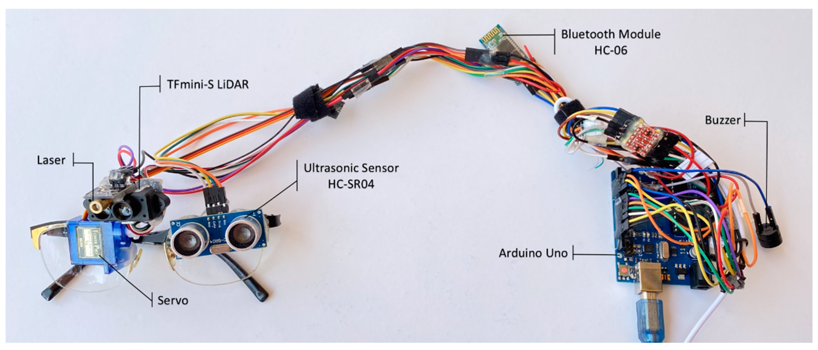


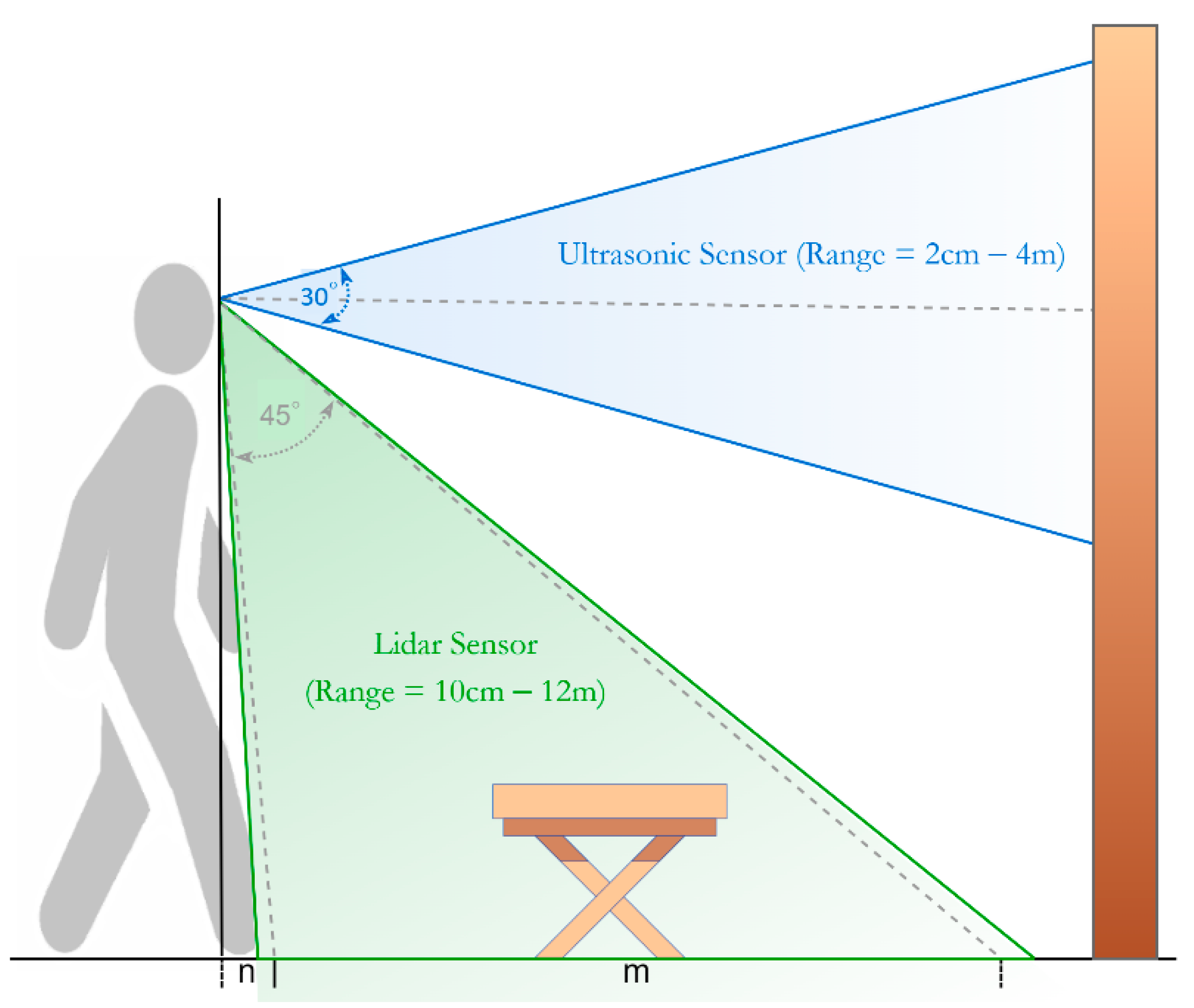
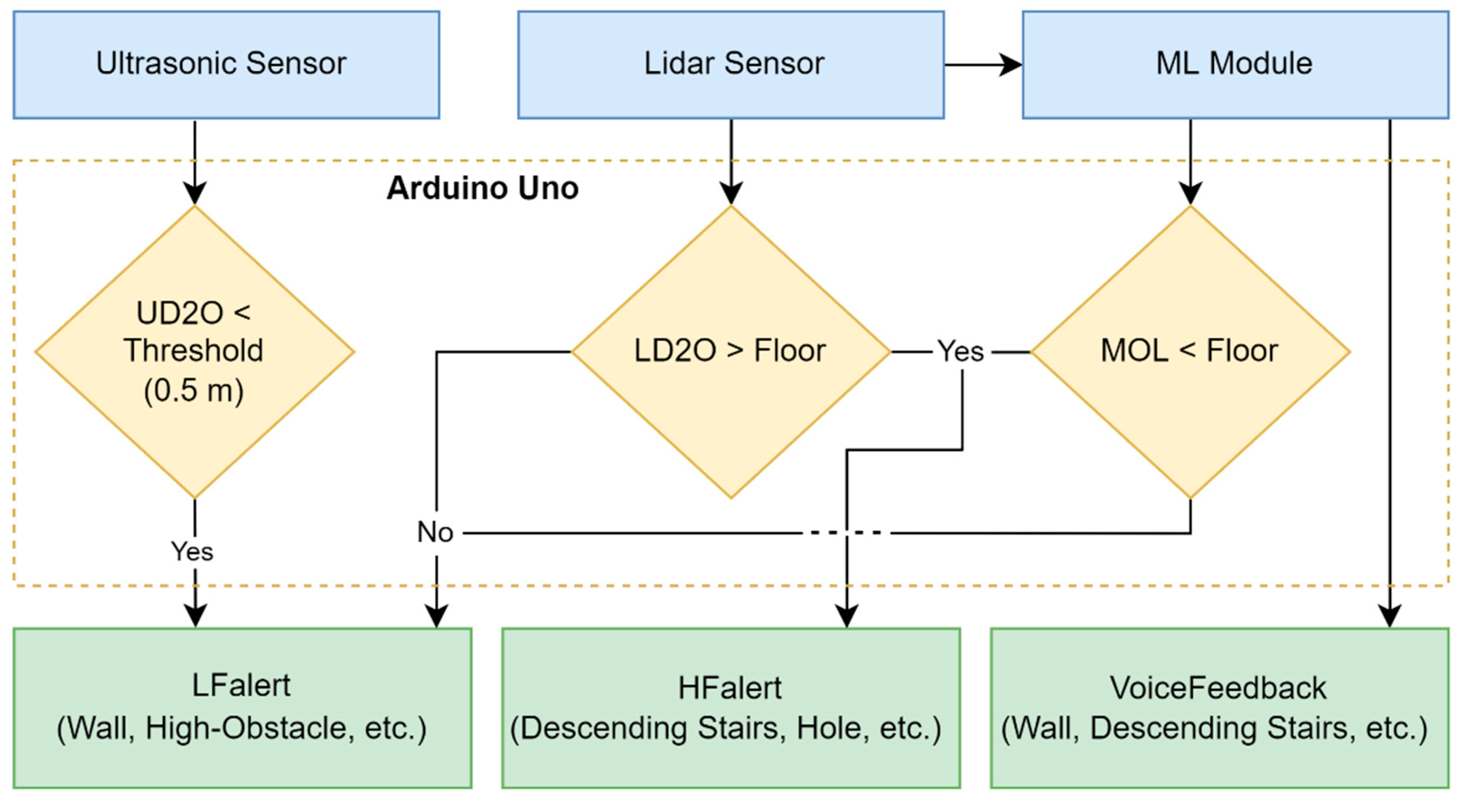

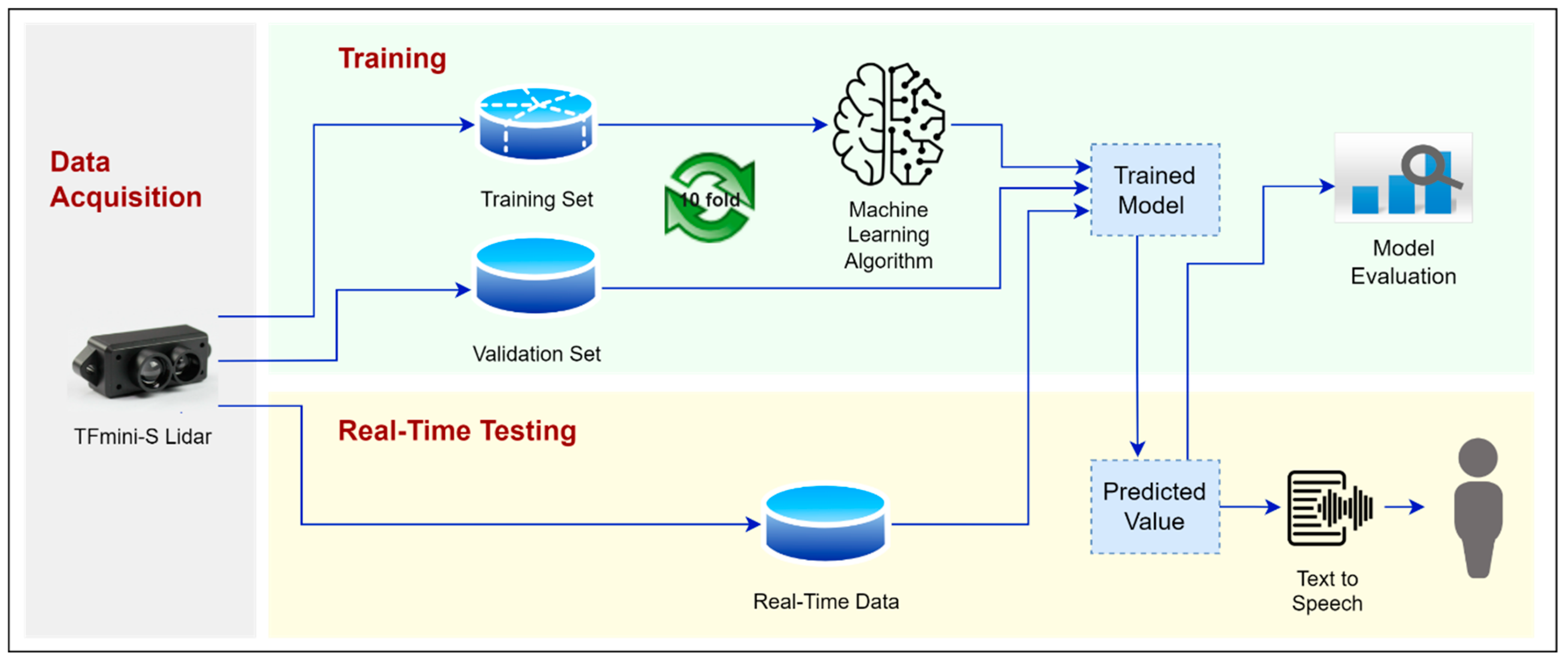


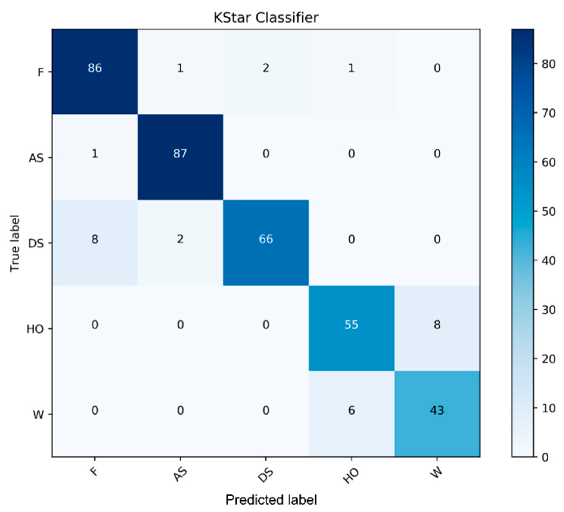


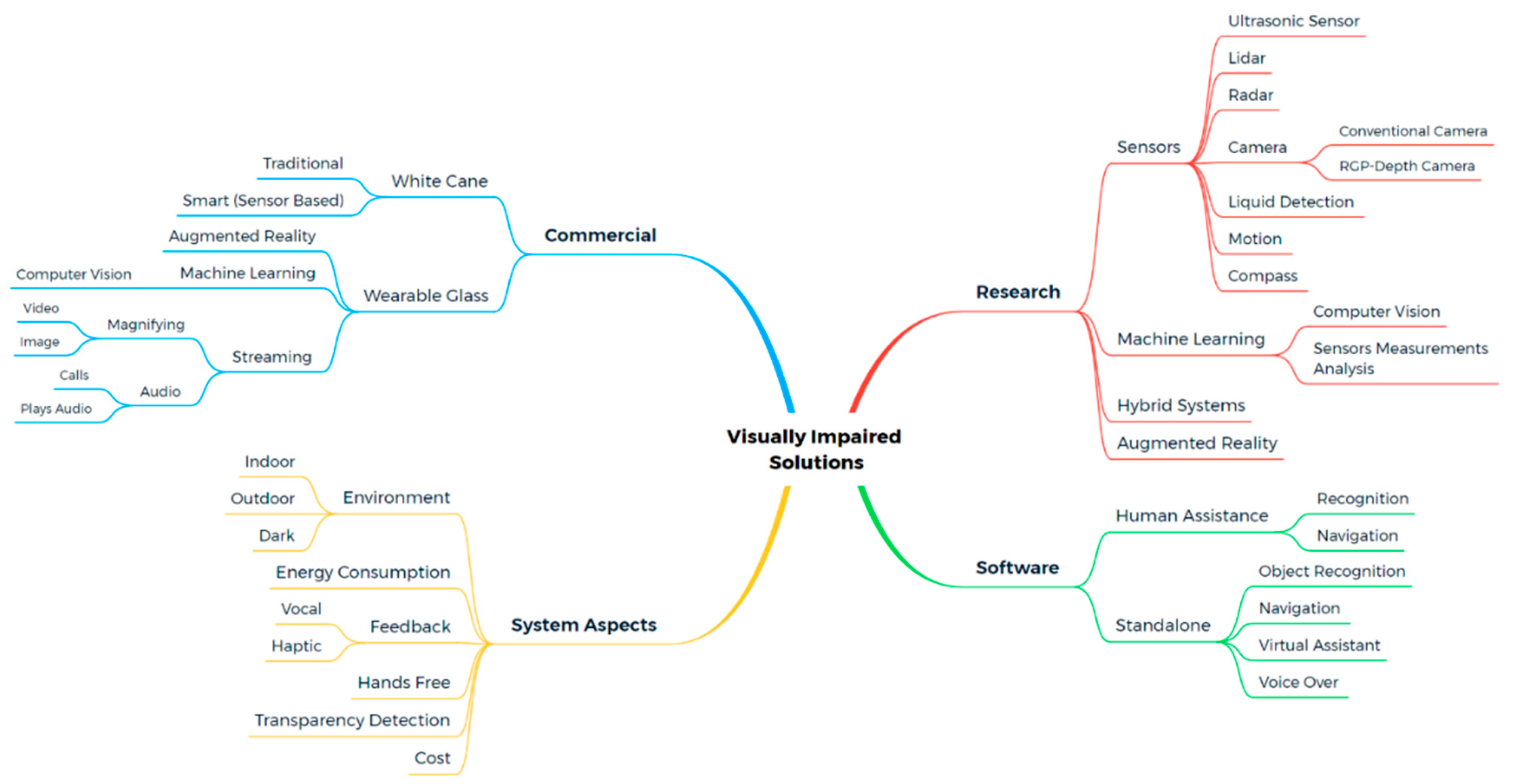