
Design and Characterization of Compact Broadband Antenna and Its MIMO Configuration for 28 GHz 5G Applications

 ,
,  , ,
, , 
Abstract
1. Introduction
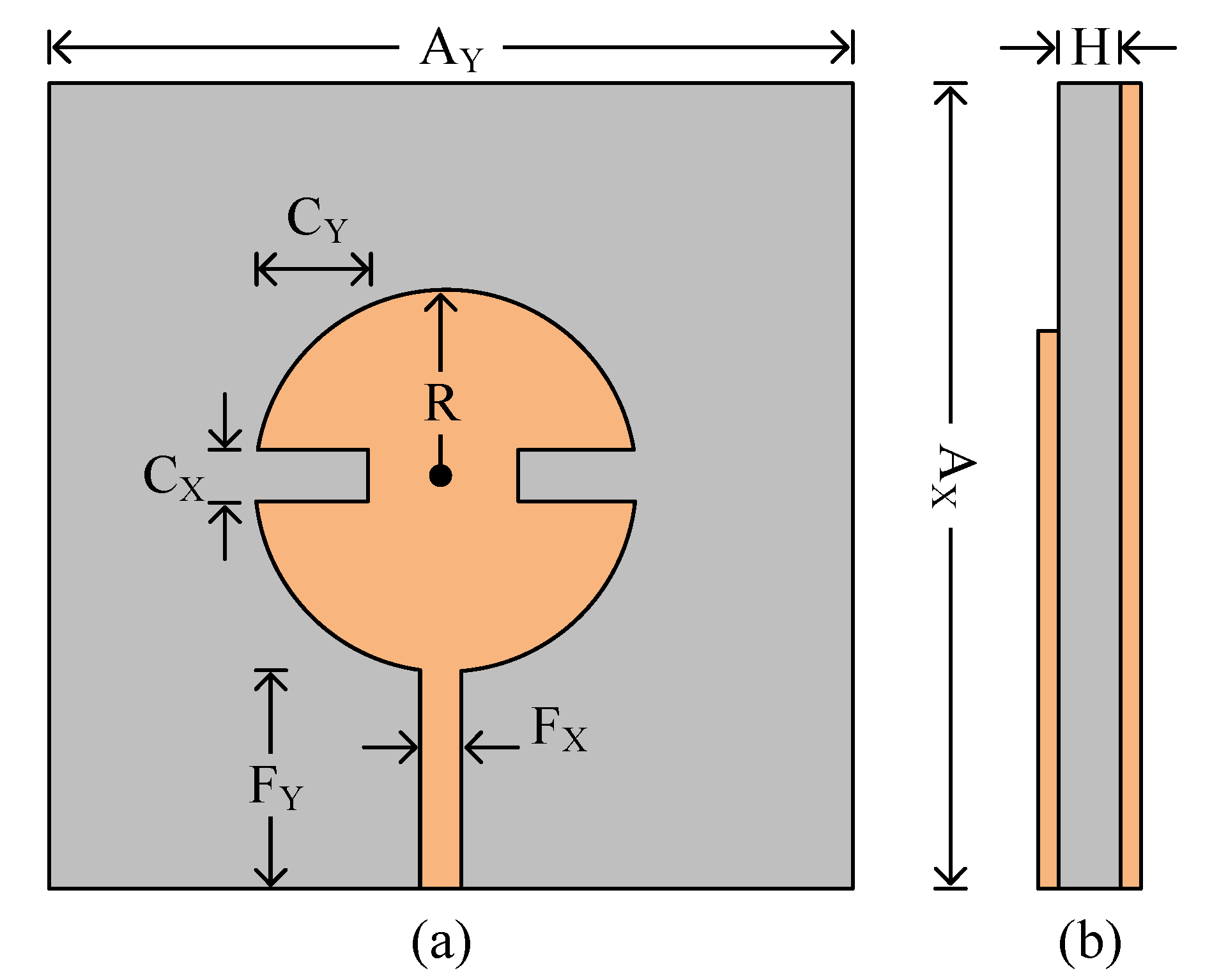
2. Single Circular Patch Antenna
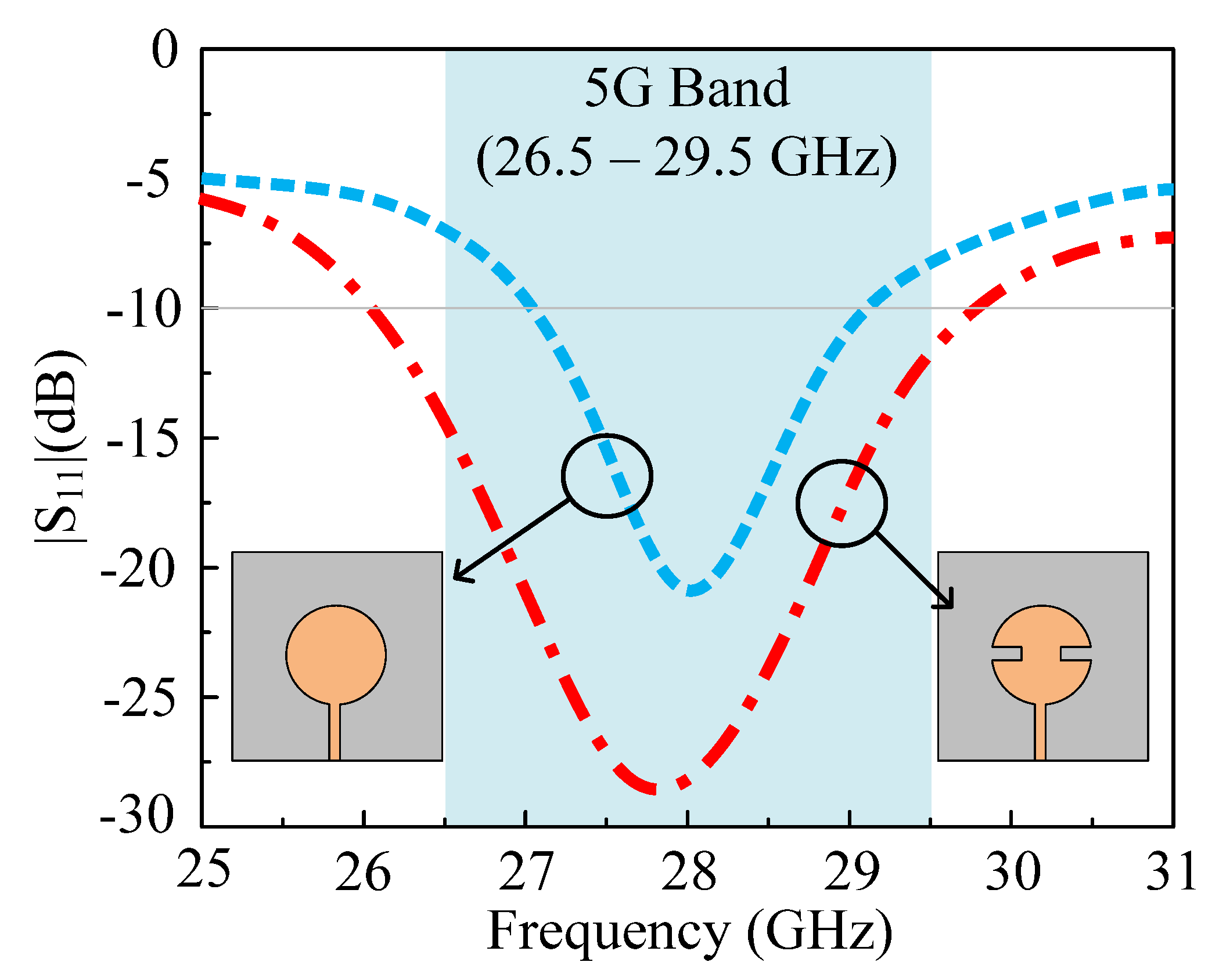
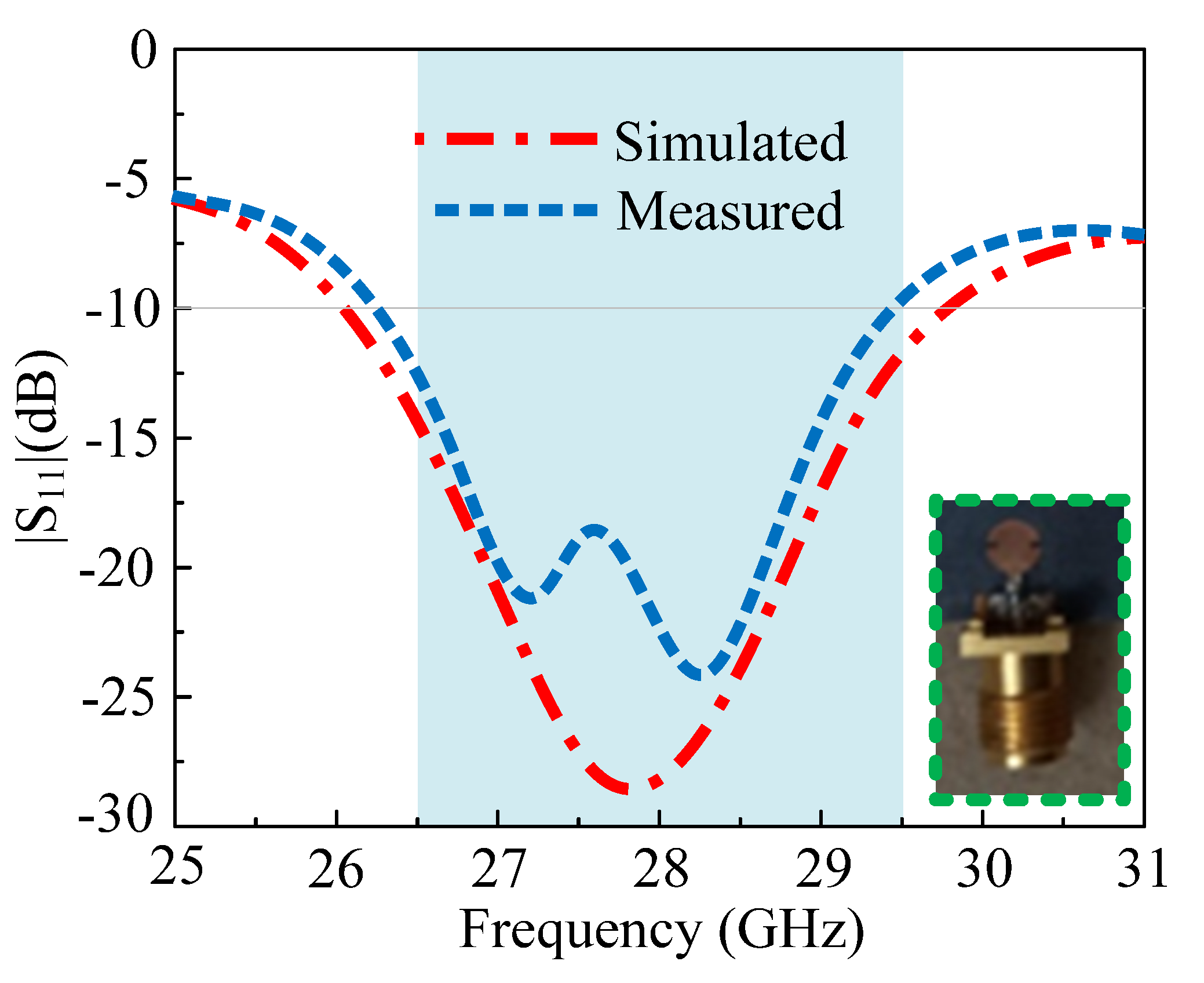
3. Simulated and Measured Results of Single Circular Patch Antenna
- a.
- Scattering Parameter
- b.
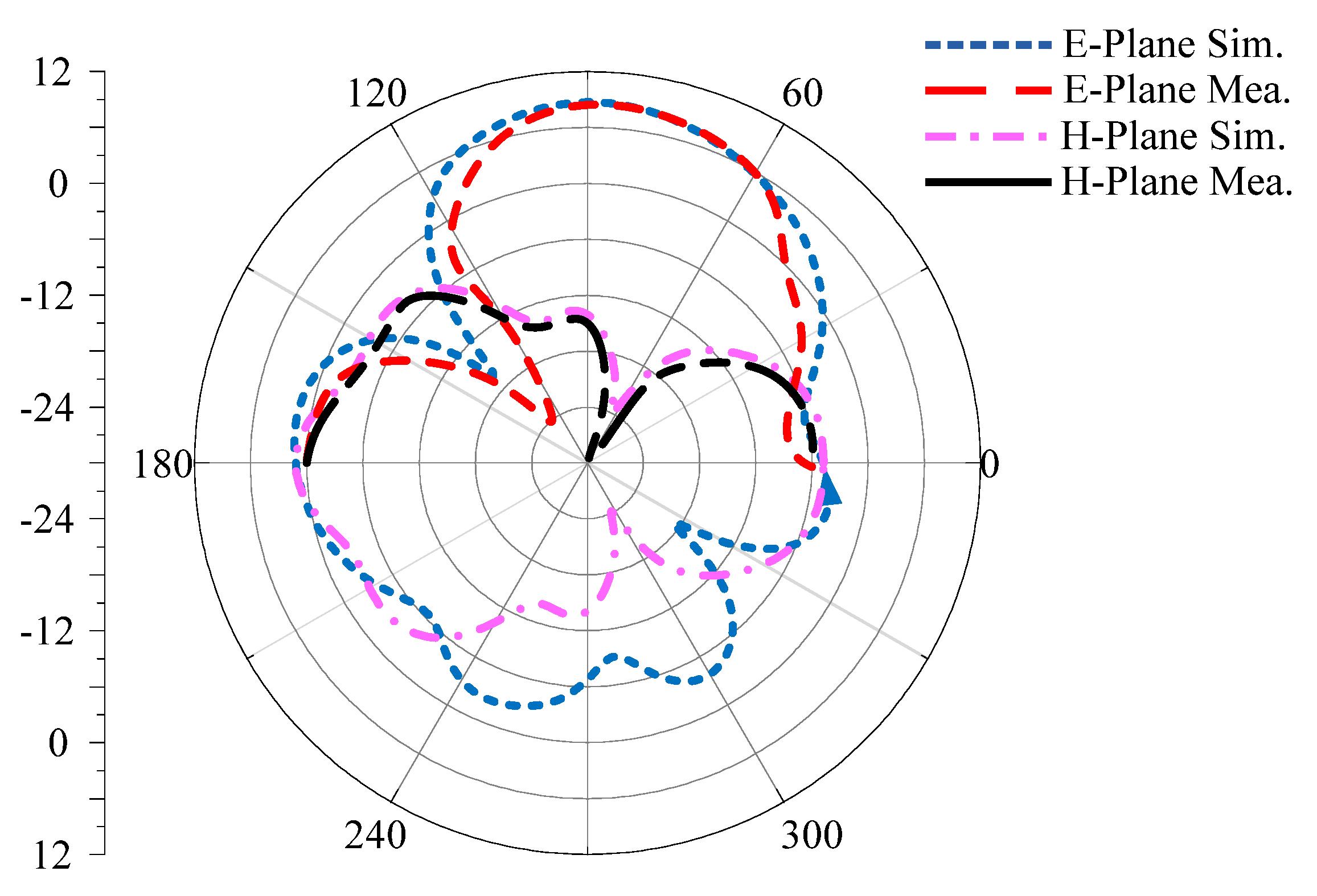
- Radiation Pattern
- c.
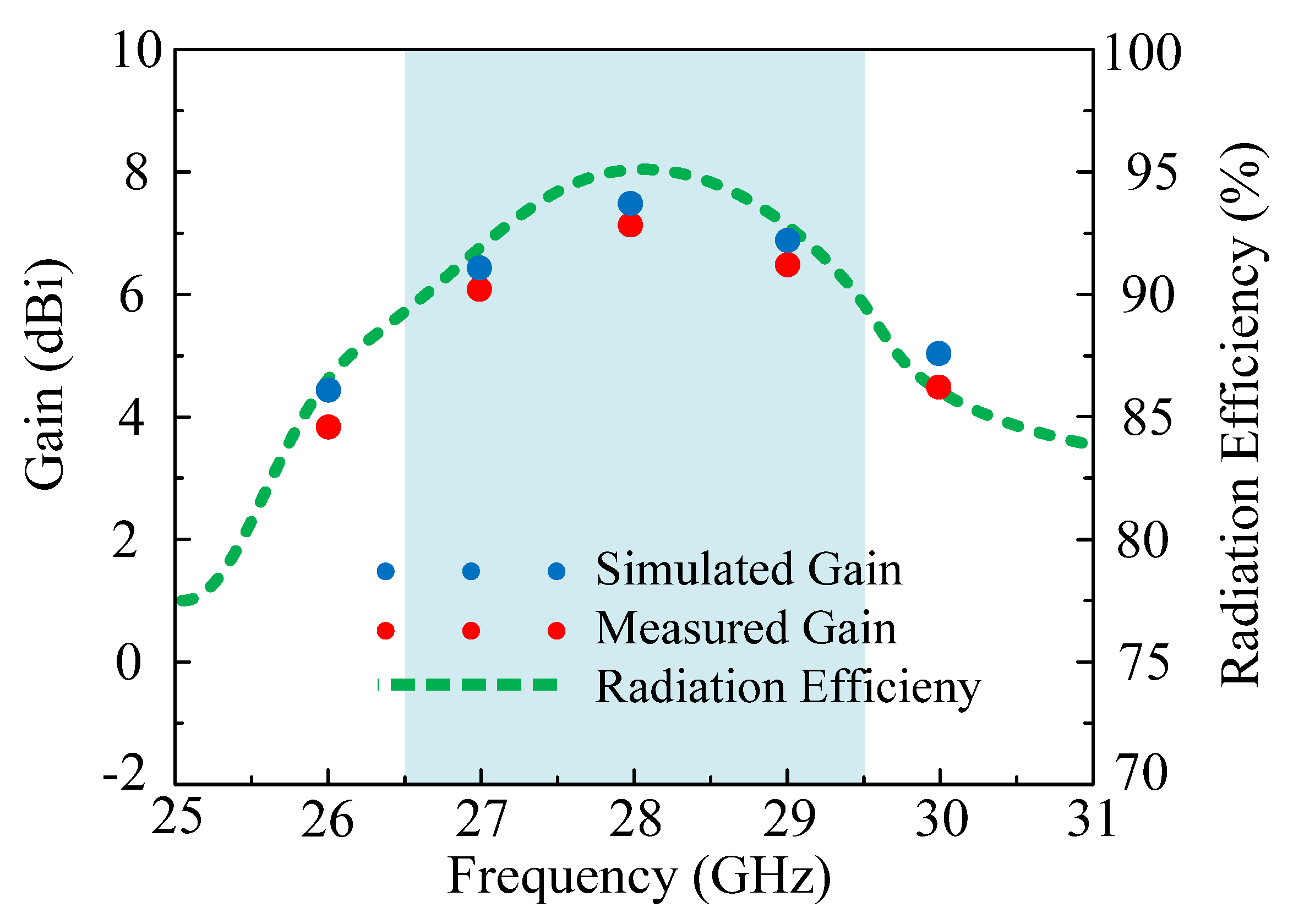
- Gain and Radiation Efficiency
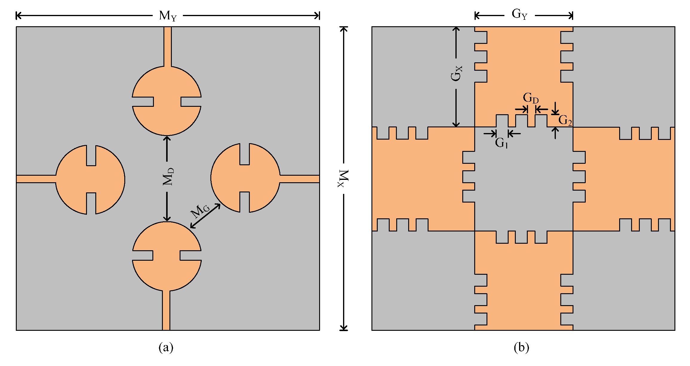
4. Four-Port MIMO Antenna for 28 GHz 5G Application
- a.
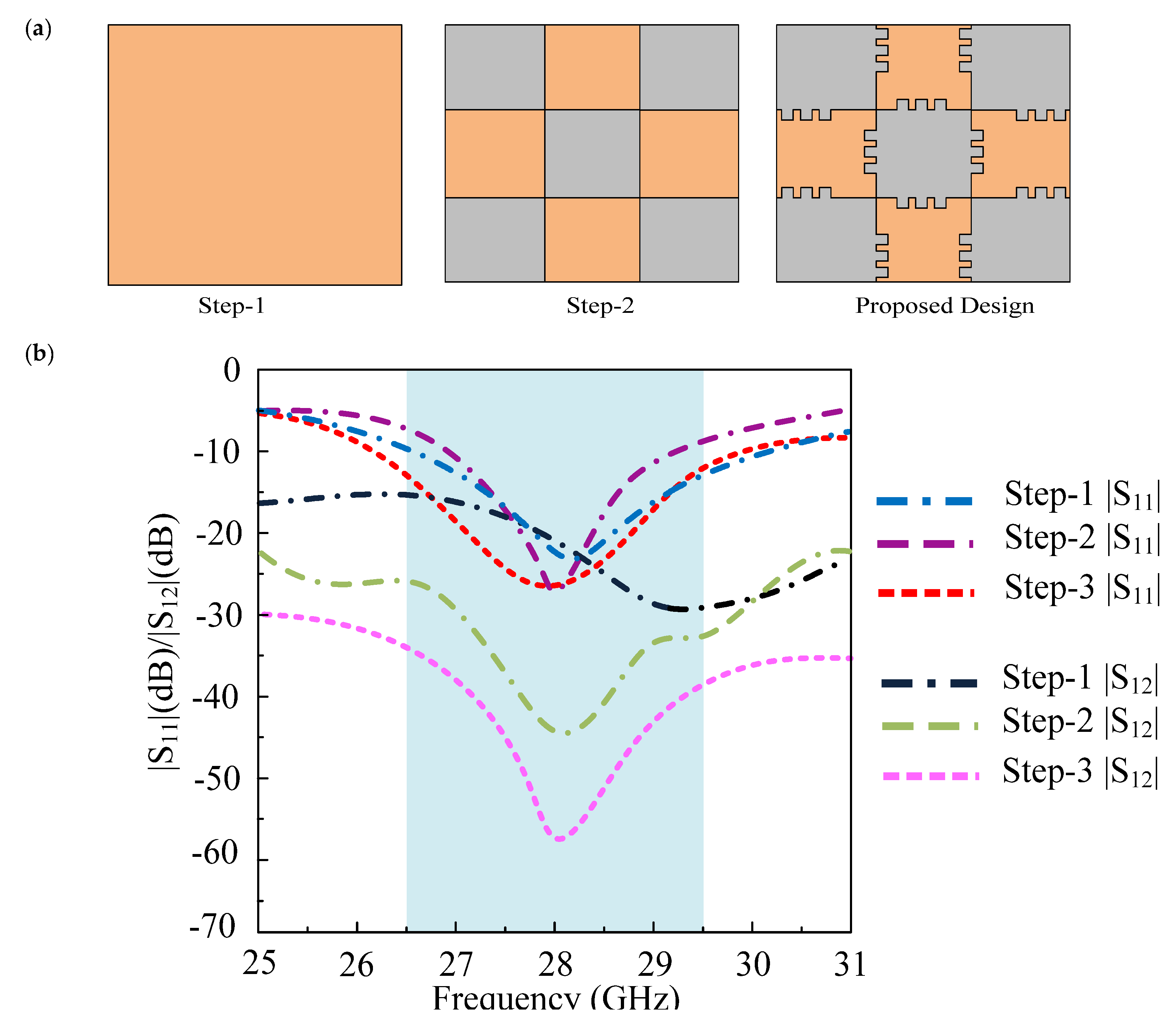
- MIMO design stages
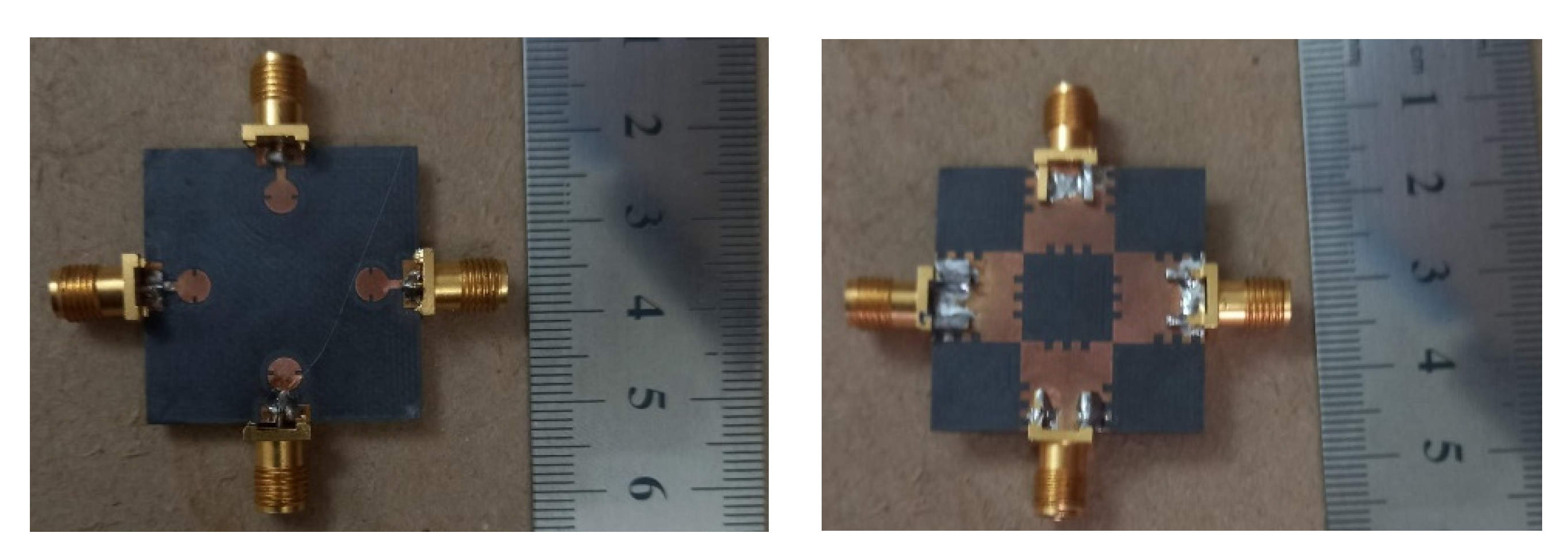
- b.
- Simulated and measured results of MIMO antenna
4.1. Scattering Parameter
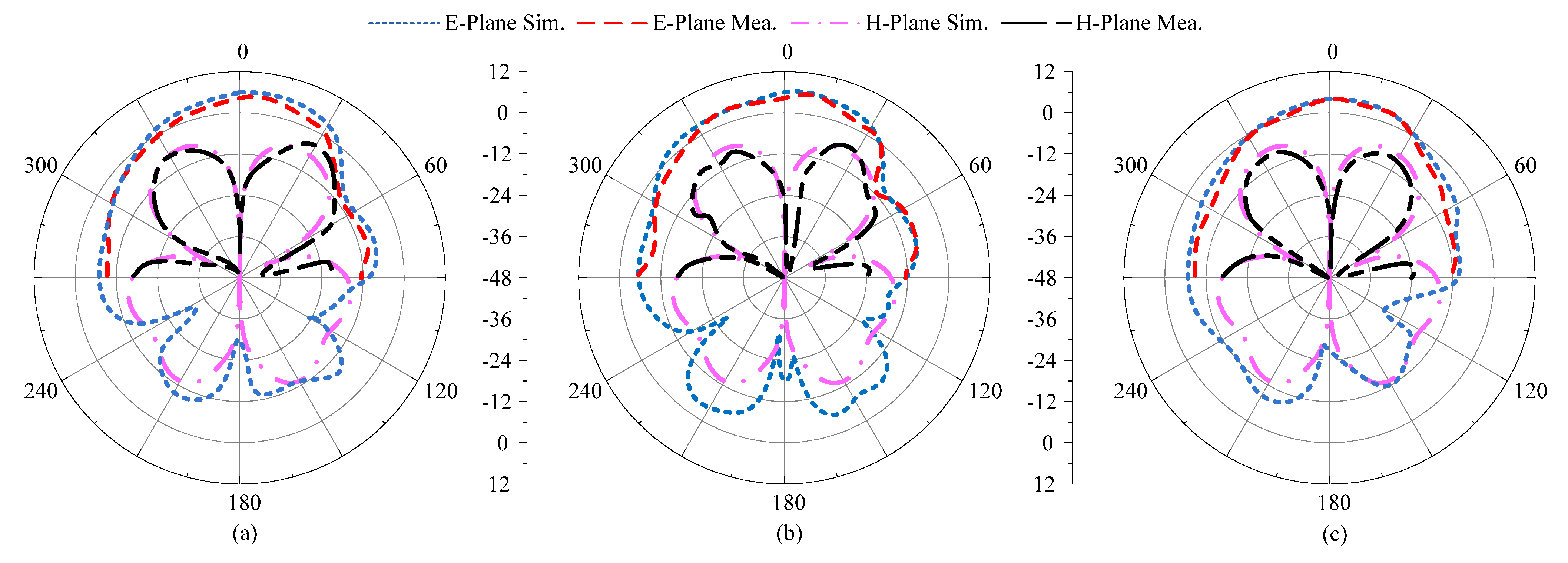
4.2. Radiation Pattern
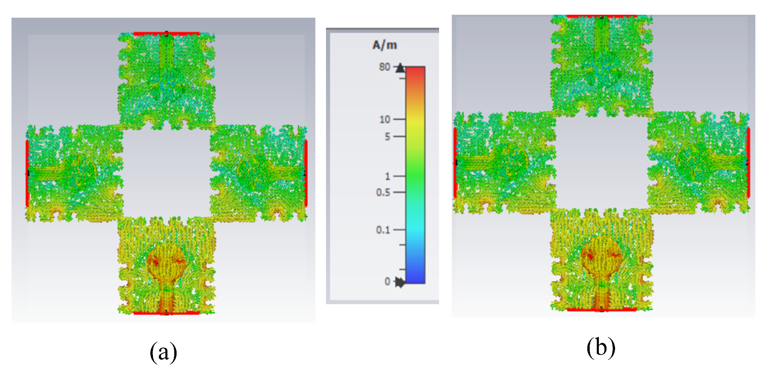
4.3. Surface Current Distribution
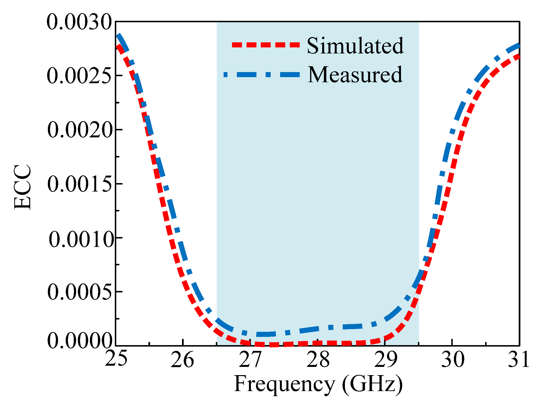
4.4. Envelop Correlation Co-Efficient
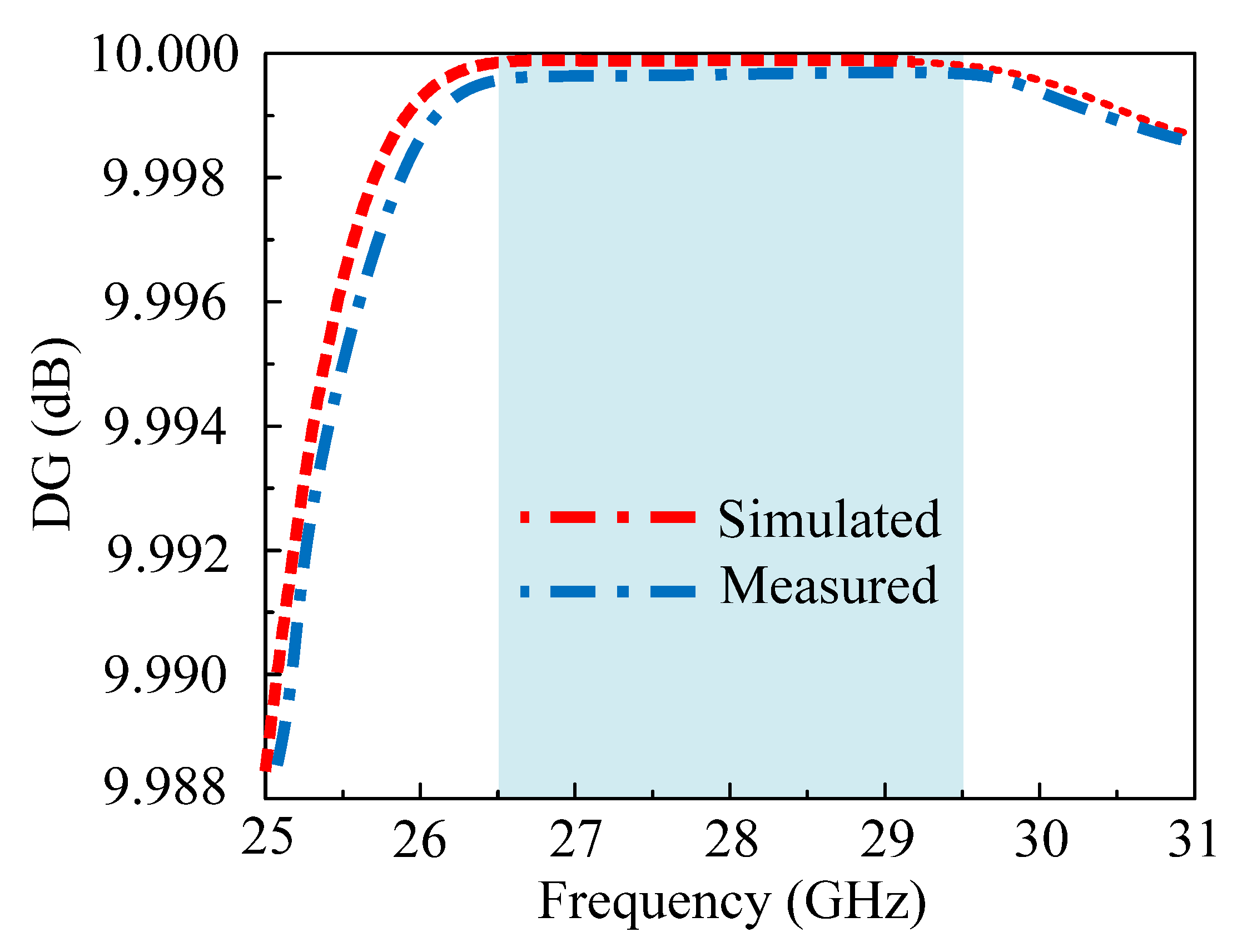
4.5. Diversity Gain (DG)
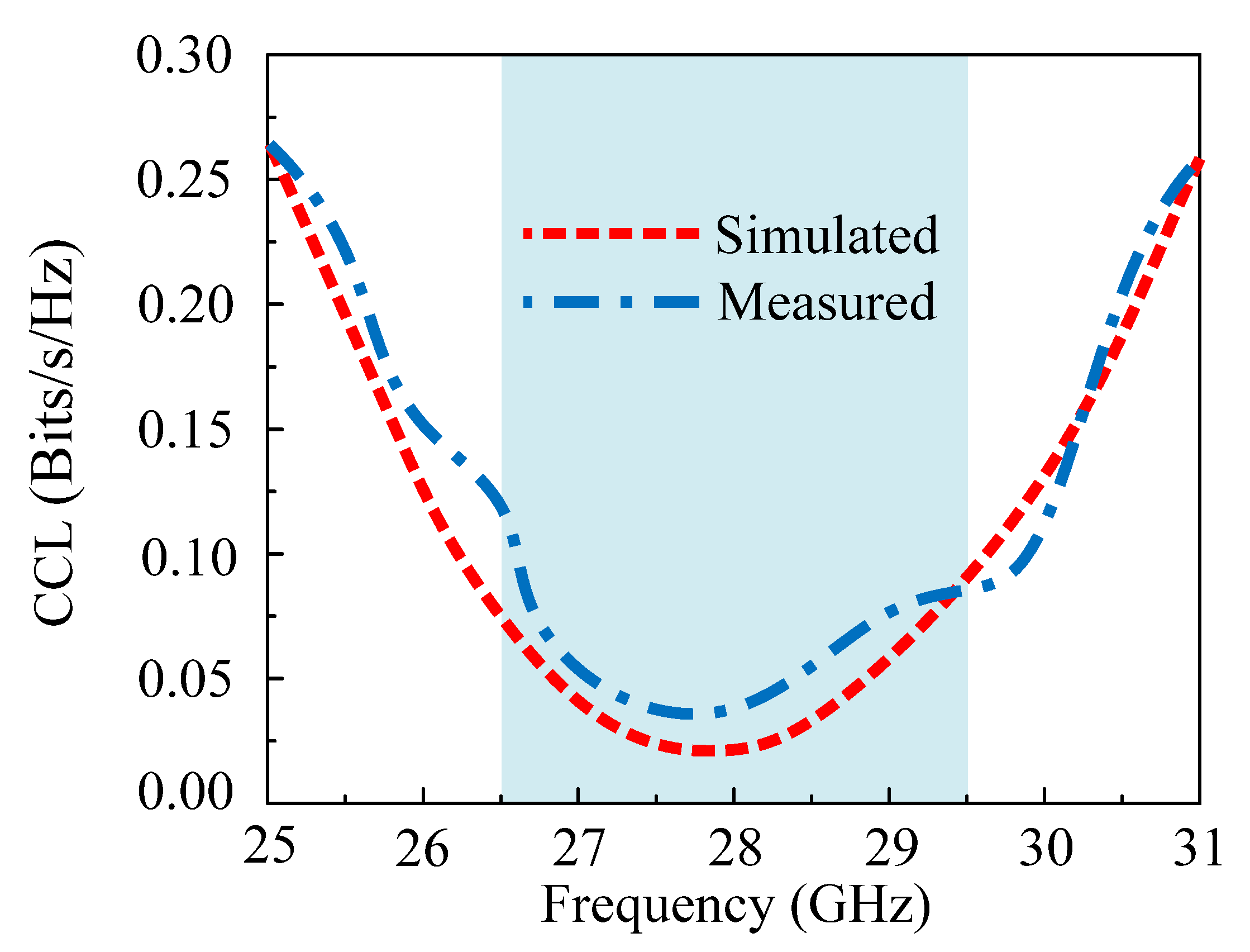
4.6. Channel Capacity Loss (CCL)
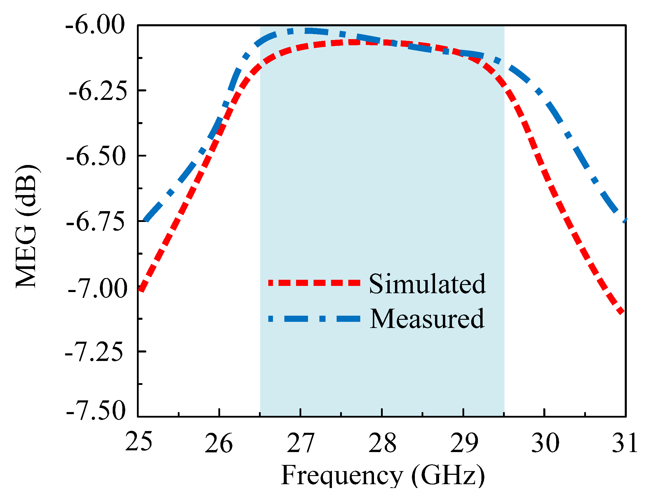
4.7. Mean Effective Gain (MEG)
5. Conclusions
Author Contributions
Funding
Institutional Review Board Statement
Informed Consent Statement
Data Availability Statement
Acknowledgments
Conflicts of Interest
References
- Andrews, J.G.; Buzzi, S.; Choi, W.; Hanly, S.V.; Lozano, A.; Soong, A.C.K.; Zhang, J.C. What will 5G be? IEEE J. Sel. Areas Commun. 2014, 32, 1065–1082. [Google Scholar] [CrossRef]
- Awan, W.A.; Zaidi, A.; Hussain, N.; Iqbal, A.; Baghdad, A. Stub loaded, low profile UWB antenna with independently controllable notch-bands. Microw. Opt. Technol. Lett. 2019, 61, 2447–2454. [Google Scholar] [CrossRef]
- Hussain, M.; Rizvi, S.M.; Abbas, A.; Nadeem, A.; Alam, I.; Iftikhar, A. A Wideband Antenna for V-Band Applications in 5G Communications. In Proceedings of the 2021 International Bhurban Conference on Applied Sciences and Technologies (IBCAST), Islamabad, Pakistan, 12–16 January 2021; pp. 1017–1019. [Google Scholar]
- Awan, W.A.; Zaidi, A.; Baghdad, A. Patch antenna with improved performance using DGS for 28GHz applications. In Proceedings of the 2019 International Conference on Wireless Technologies, Embedded and Intelligent Systems (WITS), Fez, Morocco, 3–4 April 2019; pp. 1–4. [Google Scholar] [CrossRef]
- Hussain, N.; Jeong, M.; Park, J.; Kim, N. A broadband circularly polarized fabry-perot resonant antenna using a single-layered PRS for 5G MIMO applications. IEEE Access 2019, 7, 42897–42907. [Google Scholar] [CrossRef]
- Naqvi, A.H.; Lim, S. Review of recent phased arrays for millimeter-wave wireless communication. Sensors 2018, 18, 3194. [Google Scholar] [CrossRef] [PubMed]
- Hussain, M.; Nadeem, N. A Co-Planer Waveguide Feed Dual Band Antenna with Frequency Reconfigurability for WLAN and WiMax Systems. In Proceedings of the 2019 International Conference on Electrical, Communication, and Computer Engineering (ICECCE), Swat, Pakistan, 24–25 July 2019; pp. 1–5. [Google Scholar]
- Khalid, M.; Naqvi, S.I.; Hussain, N.; Rahman, M.; Mirjavadi, S.S.; Khan, M.J.; Amin, Y. 4-Port MIMO antenna with defected ground structure for 5G millimeter wave applications. Electronics 2020, 9, 71. [Google Scholar] [CrossRef]
- Ojaroudi Parchin, N.; Basherlou, H.J.; Alibakhshikenari, M.; Parchin, Y.O.; Al-Yasir, Y.I.A.; Abd-Alhameed, R.A.; Limiti, E. Mobile-phone antenna array with diamond-ring slot elements for 5G massive MIMO systems. Electronics 2019, 8, 521. [Google Scholar] [CrossRef]
- Khalid, H.; Khalid, M.; Fatima, A.; Khalid, N. 2 × 2 MIMO antenna with defected ground structure for mm-wave 5G applications. In Proceedings of the 2019 13th International Conference on Mathematics, Actuarial Science, Computer Science and Statistics (MACS), Karachi, Pakistan, 14–15 December 2019; pp. 1–6. [Google Scholar]
- Xing, H.; Wang, X.; Gao, Z.; An, X.; Zheng, H.; Wang, M.; Li, E. Efficient Isolation of an MIMO Antenna Using Defected Ground Structure. Electronics 2020, 9, 1265. [Google Scholar] [CrossRef]
- Naqvi, S.I.; Naqvi, A.H.; Arshad, F.; Riaz, M.A.; Azam, M.A.; Khan, M.S.; Amin, Y.; Loo, J.; Tenhunen, H. An integrated antenna system for 4G and millimeter-wave 5G future handheld devices. IEEE Access 2019, 7, 116555–116566. [Google Scholar] [CrossRef]
- Ikram, M.; Sharawi, M.S.; Shamim, A. A novel very wideband integrated antenna system for 4G and 5G mm-wave applications. Microw. Opt. Technol. Lett. 2017, 59, 3082–3088. [Google Scholar] [CrossRef]
- Affandi, A.; Azim, R.; Alam, M.M.; Islam, M.T. A low-profile wideband antenna for WWAN/LTE applications. Electronics 2020, 9, 393. [Google Scholar] [CrossRef]
- Rahman, M.; NagshvarianJahromi, M.; Mirjavadi, S.S.; Hamouda, A.M. Compact UWB band-notched antenna with integrated bluetooth for personal wireless communication and UWB applications. Electronics 2019, 8, 158. [Google Scholar] [CrossRef]
- Abdullah, M.; Kiani, S.H.; Iqbal, A. Eight element multiple-input multiple-output (MIMO) antenna for 5G mobile applications. IEEE Access 2019, 7, 134488–134495. [Google Scholar] [CrossRef]
- Desai, A.; Bui, C.D.; Patel, J.; Upadhyaya, T.; Byun, G.; Nguyen, T.K. Compact Wideband Four Element Optically Transparent MIMO Antenna for mm-Wave 5G Applications. IEEE Access 2020, 8, 194206–194217. [Google Scholar] [CrossRef]
- Alreshaid, A.T.; Hussain, R.; Podilchak, S.K.; Sharawi, M.S. A dual-element MIMO antenna system with a mm-wave antenna array. In Proceedings of the 2016 10th European Conference on Antennas and Propagation (EuCAP), Davos, Switzerland, 10–15 April 2016; pp. 1–4. [Google Scholar]
- Hasan, M.N.; Seo, M. Compact omnidirectional 28 GHz 2 × 2 MIMO antenna array for 5G communications. In Proceedings of the 2018 International Symposium on Antennas and Propagation (ISAP), Busan, Korea, 23–26 October 2018; pp. 1–2. [Google Scholar]
- Jilani, S.F.; Abbasi, Q.H.; Imran, M.A.; Alomainy, A. Design and Analysis of Millimeter-Wave Antennas for the Fifth Generation Networks and Beyond. Wiley 5G Ref Essent. 5G Ref. Online 2019, 1–21. [Google Scholar] [CrossRef]
- Tu, D.T.T.; Thang, N.G.; Ngoc, N.T.; Phuong, N.T.B.; van Yem, V. 28/38 GHz dual-band MIMO antenna with low mutual coupling using novel round patch EBG cell for 5G applications. In Proceedings of the 2017 International Conference on Advanced Technologies for Communications (ATC), Busan, Korea, 23–26 October 2018; pp. 64–69. [Google Scholar]
- Saad, A.A.R.; Mohamed, H.A. Printed millimeter-wave MIMO-based slot antenna arrays for 5G networks. AEU-Int. J. Electron. Commun. 2019, 99, 59–69. [Google Scholar] [CrossRef]
- Marzouk, H.M.; Ahmed, M.I.; Shaalan, A.A. A Novel Dual-Band 28/38 GHz AFSL MIMO Antenna for 5G Smartphone Applications. J. Phys. Conf. Ser. 2020, 1447, 012025. [Google Scholar] [CrossRef]
- Altaf, A.; Iqbal, A.; Smida, A.; Smida, J.; Althuwayb, A.A.; Kiani, S.H.; Alibakhshikenari, M.; Falcone, F.; Limiti, E. Isolation improvement in UWB-MIMO antenna system using slotted stub. Electronics 2020, 9, 1582. [Google Scholar] [CrossRef]
- Ta, S.X.; Choo, H.; Park, I. Broadband printed-dipole antenna and its arrays for 5G applications. IEEE Antennas Wirel. Propag. Lett. 2017, 16, 2183–2186. [Google Scholar] [CrossRef]
- Zhang, J.; Ge, X.; Li, Q.; Guizani, M.; Zhang, Y. 5G millimeter-wave antenna array: Design and challenges. IEEE Wirel. Commun. 2016, 24, 106–112. [Google Scholar] [CrossRef]
- Arabi, O.; See, C.H.; Ullah, A.; Ali, N.; Liu, B.; Abd-Alhameed, R.; McEwan, N.J.; Excell, P.S. Compact Wideband MIMO Diversity Antenna for Mobile Applications Using Multi-Layered Structure. Electronics 2020, 9, 1307. [Google Scholar] [CrossRef]
- Wani, Z.; Abegaonkar, M.P.; Koul, S.K. A 28-GHz antenna for 5G MIMO applications. Prog. Electromagn. Res. 2018, 78, 73–79. [Google Scholar] [CrossRef]
- Sehrai, D.A.; Abdullah, M.; Altaf, A.; Kiani, S.H.; Muhammad, F.; Tufail, M.; Irfan, M.; Glowacz, A.; Rahman, S. A Novel High Gain Wideband MIMO Antenna for 5G Millimeter Wave Applications. Electronics 2020, 9, 1031. [Google Scholar] [CrossRef]
- Balanis, C.A. Antenna Theory: Analysis and Design; John Wiley & Sons: Hoboken, NJ, USA, 2016. [Google Scholar]
- Hakim, M.L.; Uddin, M.J.; Hoque, M.J. 28/38 GHz Dual-Band Microstrip Patch Antenna with DGS and Stub-Slot Configurations and Its 2×2 MIMO Antenna Design for 5G Wireless Communication. In Proceedings of the 2020 IEEE Region 10 Symposium (TENSYMP), Dhaka, Bangladesh, 5–7 June 2020; pp. 56–59. [Google Scholar] [CrossRef]
- Ohnimus, F.; Maaß, U.; Fotheringham, G.; Curran, B.; Ndip, I.; Fritzsch, T.; Wolf, J.; Guttowski, S.; Lang, K. Design and Comparison of 24 GHz Patch Antennas on Glass Substrates for Compact Wireless Sensor Nodes. Int. J. Microw. Sci. Technol. 2010, 2010, 535307. [Google Scholar] [CrossRef][Green Version]
- Gu, X.; Liu, D.; Baks, C.; Tageman, O.; Sadhu, B.; Hallin, J.; Rexberg, L.; Valdes-Garcia, A. A multilayer organic package with 64 dual-polarized antennas for 28GHz 5G communication. In Proceedings of the 2017 IEEE MTT-S International Microwave Symposium (IMS), Honololu, HI, USA, 4–9 June 2017; pp. 1899–1901. [Google Scholar] [CrossRef]
- Hussain, N.; Awan, W.A.; Ali, W.; Naqvi, S.I.; Zaidi, A.; Le, T.T. Compact wideband patch antenna and its MIMO configuration for 28 GHz applications. AEU-Int. J. Electron. Commun. 2021, 132, 153612. [Google Scholar] [CrossRef]
- Zahra, H.; Awan, W.A.; Ali, W.A.E.; Hussain, N.; Abbas, S.M.; Mukhopadhyay, S. A 28 GHz Broadband Helical Inspired End-Fire Antenna and Its MIMO Configuration for 5G Pattern Diversity Applications. Electronics 2021, 10, 405. [Google Scholar] [CrossRef]


| Ref. | Antenna Size (mm2) | Bandwidth (GHz) | Peak Gain (dBi) |
|---|---|---|---|
| [4] | 5 × 5 | 0.75 | 7 |
| [28] | 11 × 31 | 5 | 10 |
| [31] | 22 × 17 | 4.5 | 8 |
| [32] | 2 × 2.5 | 0.9 | 5.5 |
| [33] | 11 × 15 | 3 | 3 |
| [34] | 15 × 15 | 6.4 | 5.42 |
| [35] | 15 × 10 | 3.8 | 5.83 |
| This Work | 10 × 10 | 3.52 | 7.1 |
| Ref | Dimension (mm × mm) | No. of Ports | Bandwidth (GHz) | Operating Frequency (GHz) | Mutual Coupling (dB) | Gain (dBi) | ECC (dB) | CLL (Bits/s/Hz) |
|---|---|---|---|---|---|---|---|---|
| [8] | 30 × 35 | 4 | 4.1 | 28 | >−22 | 8.3 | 0.5 | 0.4 |
| [10] | 28 × 30 | 4 | 3 | 27 | >−21 | 6.2 | 0.05 | 0.2 |
| [11] | 12.5 × 12.5 | 4 | 2 | 35 | >−15 | 6 | 0.02 | - |
| [13] | 115 × 65 | 4 | 1.22 | 28.5 | >−12 | 4.85 | 0.1 | - |
| [21] | 11 × 31 | 4 | 5 | 28 | >−18 | 10 | 0.04 | 0.5 |
| [27] | 60 × 100 | 2 | 1.7 | 28 | >−20 | 9.8 | - | 0.002 |
| This work | 30 × 30 | 4 | 4 | 27 | >−30 | 7.1 | 0.0005 | 0.15 |
Publisher’s Note: MDPI stays neutral with regard to jurisdictional claims in published maps and institutional affiliations. |
© 2022 by the authors. Licensee MDPI, Basel, Switzerland. This article is an open access article distributed under the terms and conditions of the Creative Commons Attribution (CC BY) license (https://creativecommons.org/licenses/by/4.0/).
Share and Cite
Hussain, M.; Mousa Ali, E.; Jarchavi, S.M.R.; Zaidi, A.; Najam, A.I.; Alotaibi, A.A.; Althobaiti, A.; Ghoneim, S.S.M. Design and Characterization of Compact Broadband Antenna and Its MIMO Configuration for 28 GHz 5G Applications. Electronics 2022, 11, 523. https://doi.org/10.3390/electronics11040523
Hussain M, Mousa Ali E, Jarchavi SMR, Zaidi A, Najam AI, Alotaibi AA, Althobaiti A, Ghoneim SSM. Design and Characterization of Compact Broadband Antenna and Its MIMO Configuration for 28 GHz 5G Applications. Electronics. 2022; 11(4):523. https://doi.org/10.3390/electronics11040523
Chicago/Turabian StyleHussain, Musa, Esraa Mousa Ali, Syed Muhammad Rizvi Jarchavi, Abir Zaidi, Ali Imran Najam, Abdullah Alhumaidi Alotaibi, Ahmed Althobaiti, and Sherif S. M. Ghoneim. 2022. "Design and Characterization of Compact Broadband Antenna and Its MIMO Configuration for 28 GHz 5G Applications" Electronics 11, no. 4: 523. https://doi.org/10.3390/electronics11040523
APA StyleHussain, M., Mousa Ali, E., Jarchavi, S. M. R., Zaidi, A., Najam, A. I., Alotaibi, A. A., Althobaiti, A., & Ghoneim, S. S. M. (2022). Design and Characterization of Compact Broadband Antenna and Its MIMO Configuration for 28 GHz 5G Applications. Electronics, 11(4), 523. https://doi.org/10.3390/electronics11040523