1. Introduction
Power grids are changing in diverse areas and moving toward emergent smart grids. In addition to the innovation of information and communication technologies, the next decades will experience a more controlled, collaborative, and dynamic integration of electric mobility systems, renewable energy sources (RES), and power conditioners to diminish power quality issues [
1,
2]. Additionally, unified control strategies for grid-connected inverters are fundamental to diminish disturbances from the electrical power grid point of view [
3]. Regarding electric mobility, it denotes a noteworthy involvement toward sustainability and efficiency in the transport sector [
4,
5], where electric vehicles (EVs), hybrid EVs, fuel cell vehicles, and electric bicycles are included as main tendencies [
6,
7]. Despite the representativeness of electric mobility, a broader dissemination has been constrained by some technical restrictions, with emphasis on embryonic available charging stations. Furthermore, additional difficulties arise due to the considerable introduction of electric mobility, which is correlated with power quality. Hence, its introduction into the power grid, independently of the charging mode or the structure of charging station, must consider the prevention of power quality characteristics [
8,
9], must be optimized in terms of interaction with other electrical appliances [
10], and must take their collaborative interface with paradigms of microgrids [
11], smart grids and smart homes [
12], and cooperative smart homes [
13]. A review of EV technologies, charging strategies, standards, and optimization is presented in [
14], while in [
15], a detailed review on power electronic technologies for EVs is presented. Regarding the EV introduction, it is also fundamental to consider the innovative methods for charging demand, both in terms of power market and renewables integration as well as infrastructure planning [
16,
17]. In such reality, from the moment that the EV is plugged-in, and by means of the utilization of bidirectional chargers, the possibility of the EV participation in programs of power management is an added value to the smart grid. Such possibility is identified as the vehicle-to-grid (V2G) strategy [
18]. The consequent benefits of participating in V2G strategies targeting the balance power demand in smart grids is scrutinized in [
19], while its effects and challenges in the power grid perspective are accessible in [
20]. Despite the tremendous contributions of V2G for power management, the interaction among the EV and smart grids is not only limited to such interaction, since other pertinent prospects are already identified for different context in smart grids, as confirmed and validated in [
21,
22].
In addition to electric mobility, the considerable installation of RES in different scenarios, from microgeneration to large-scale, is also contributing to revolutionize the power grids and to the expansion of microgrids and hybrid AC/DC grid scenarios [
23]. The cooperation between EVs and renewables forces the adoption of new conditions of power management, also targeting novel opportunities to appear, considering the power grid constraints [
24]. The influence of EVs in different modes aiming to stabilize the power grid voltage and with the introduction of renewables is accessible in [
25]. Smart EV charging strategies, supported by algorithms to maximize the collaboration with renewables, are proposed in [
26]. A specific power management stratagem supported by the integration of EVs and renewables with different power profiles is offered in [
27]. A cost minimization of EV charging stations with renewables is presented in [
28]. The impact of EVs and renewables, in particular photovoltaics (PVs), on future power production in the point of view of investment, is discussed in [
29]. Nevertheless, the aforementioned studies and implementation are fundamentally established by resorting to control algorithms targeting the maximization of power production from renewables for EV charging, maximizing the cost benefits of the user, and establishing power management strategies compliant with both parts; however, the hardware structures are omitted. Moreover, it is not mentioned how the power converters interact with each other, which is of interest since not all control strategies can be implemented, as they depend on flexibility of electronic power converters. A system to interface a DC–DC EV charger and PV panels with the power grid is investigated in [
30], but the details of the used topology are not discussed, nor are the power quality issues. An innovative multimode single-leg power converter is suggested in [
31] to control the power flow between DC technologies, but without interfacing the power grid. A multi-port topology used to combine EVs and renewables with the power grid is proposed in [
32], but the disadvantage relies on the use of two converters for interfacing the power grid: an active rectifier and a grid-tie inverter. An approach considering EVs, renewables, and energy storage systems in the perspective of the power grid independence is presented in [
33], but considering independent power systems for each technology. Nonetheless, power quality concerns are not considered in any of these works.
Analyzing the vectors of electric mobility, renewables, and power quality, some similarities, mainly about the AC–DC converters, are recognized. Therefore, an opportunity is identified to converge to a unified power electronics topology toward the future smart grids and allowing for improvements in efficiency, cost reduction, weight, and volume. A unified topology to interface EVs and PV panels is presented in [
34], including an experimental validation, but for single-phase power grids and using a conventional AC–DC grid-tied converter. An innovative control for renewables and EV charging stations also contributing to improving power quality is proposed in [
35], but considering a conventional three-phase AC–DC grid-tied converter. A unified system for interfacing an EV and renewables is presented in [
36], where the PV panels are directly linked to the DC-link and the system interfaces the single-phase power grid, thereby presenting the main disadvantage compared with that which is proposed in this paper. A solar-powered EV charger is presented in [
37]. An EV charger with the possibility to compensate power quality problems is presented in [
38], but this is only problems related to the power factor and for single-phase installations.
It has been verified by the analysis of the previous references, that there is no solution in the literature that contemplates all the proposals presented in this paper at the same time; therefore, the main contribution of this paper is related to the fact that only one interface with the power grid is required to encompass three central features: renewables, electric mobility, and power quality. A three-phase, four-quadrant structure with one AC-side and two DC-side interfaces, with interleaved-based operation in both sides, is proposed, offering several functionalities mainly for the power grid. In summary, the main contributions of this paper include: (i) A three-phase interleaved-based unified topology that allows the integration of EV (directly to perform the DC charging) and renewables (PV panels) using a single AC interface (i.e., compared with the traditional solutions, permits to reduce the number of AC–DC power converters); (ii) In the AC interface, additionally to the operation as an active rectifier and as a grid-tied inverter, and always in an interleaved-base operation, it is possible to define control strategies for the operation as an active power conditioner (according to the requirements of the power grid in terms of power quality); (iii) The AC interface operates in interleaved mode, with significant advantages over conventional solutions, which is ensured for all the operation modes; (iv) In both DC interfaces, i.e., for the EV and for the PV, the operation is also in multilevel mode, presenting several advantages over conventional solutions; (v) Experimental validation of the main operations, with the developed prototype directly connected to the power grid (without any type of voltage source to emulate the power grid, and without any type of coupling transformer), and using developed power electronics technology validated in a laboratory.
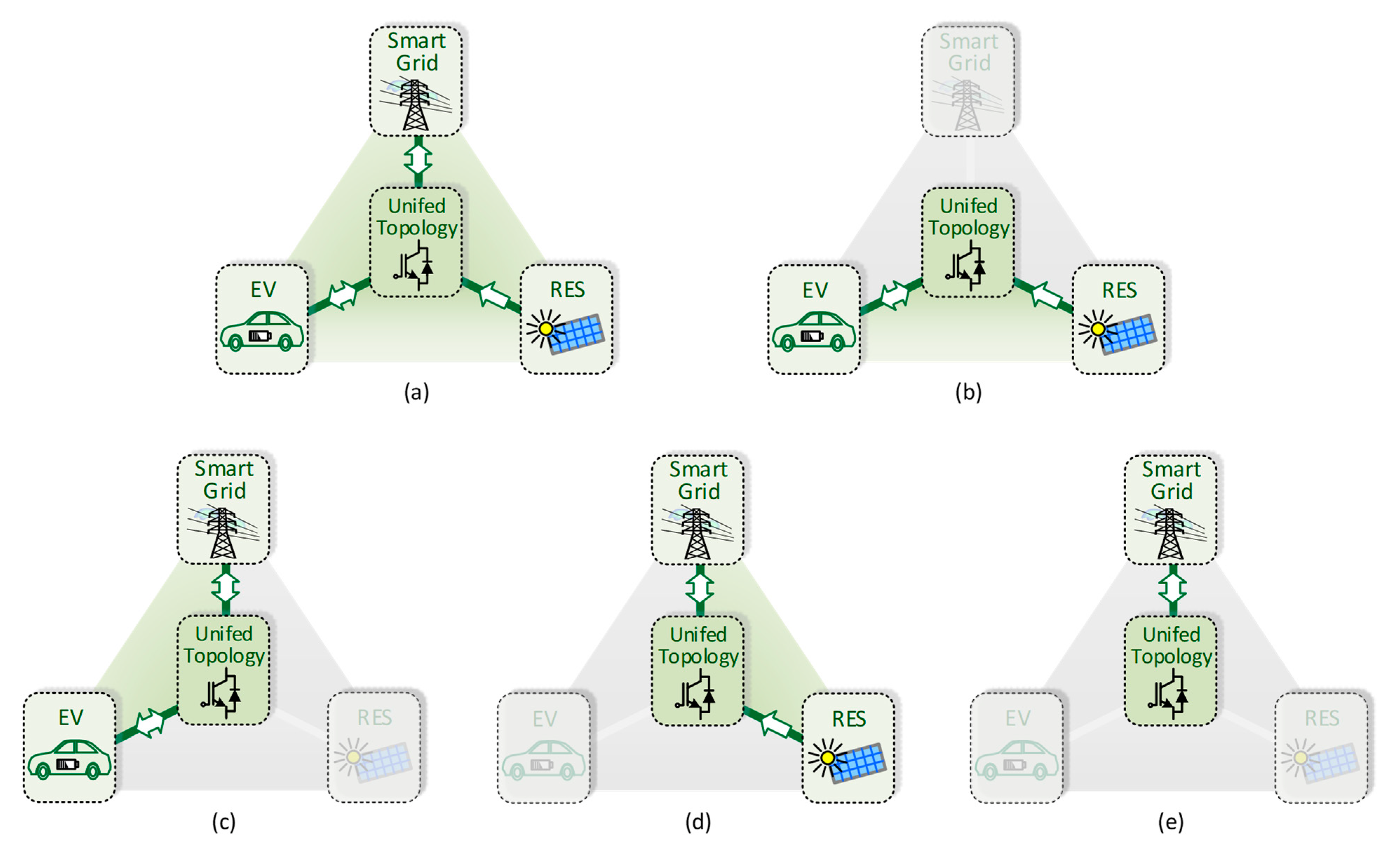
The contextualization of the proposed unified topology connected to the smart grid is presented in
Figure 1. This figure summarizes the operation modes, distinguished as: (a) Interfacing the EV and the RES with the power grid (with or without active power filtering); (b) Interfacing only the EV with the RES; (c) Interfacing only the EV with the power grid (with or without active power filtering); (d) Interfacing only the RES with the power grid (with or without active power filtering); (e) Interfacing only the power grid with active power filtering.
After this introduction presenting the subject of this article, the proposed structure, and the working principle of each of the converters and their contextualization is presented in
Section 2. The individual control algorithms for each interface (with the EV, with the RES, and with the power grid) are presented in
Section 3, highlighting the digital implementation, and identifying dependencies with each other. A computational and an experimental validation covering the most representative modes of operation are presented in
Section 4. Finally, the main conclusions are given in
Section 5.
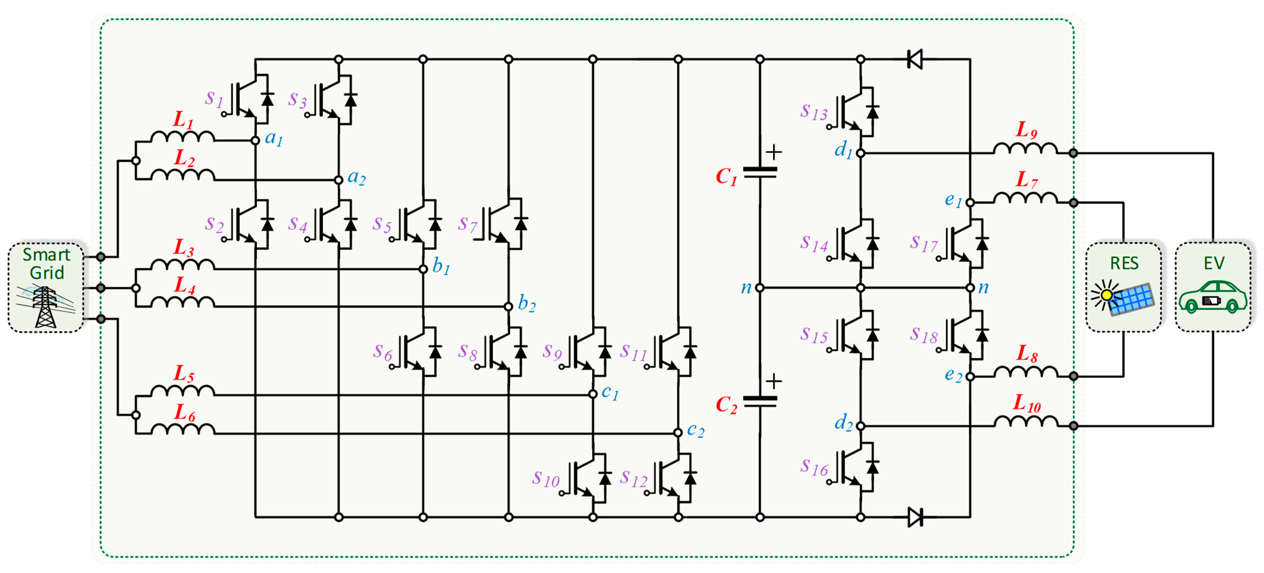
2. Structure of the Proposed Unified Topology
The proposed structure is shown in the
Figure 2. On the AC-side, it is of the three-phase type, with neutral wire, an interleaved structure for each phase, introducing significant advantages over traditional solutions, namely in what concerns the reduction of the current ripple. On the AC-side, the structure is composed of two legs for each phase, each one with the respective coupling filter, resulting in a total of six legs in connection with the power grid. The DC-link has a midpoint linked to the neutral wire, which is also fundamental to the other technologies (i.e., EV and RES) in terms of operation of the proposed structure. Specifically, the DC-link is where all power transactions, from all AC and DC interfaces, are made; therefore, it is imperative to have such voltages well controlled even when operating with sudden variations of power. The 12 insulated gate bipolar transistors (IGBTs) on the AC-side are individually controlled to allow the proposed structure for injecting or receiving power from the power grid, based on the operation of the DC interfaces, as well as for keeping the DC-link voltage controlled. As a main feature, in normal conditions of exchanging active power with the power grid, the operation with sinusoidal currents on the AC-side stands out, not contributing to the deterioration of the power quality. In addition, the unified topology also operates with balanced currents on the AC-side, even if the voltages are not properly balanced. This situation necessarily forces the unified topology not to operate with balanced power by the three phases; on the other hand, it does not contribute to harm the power grid in terms of power quality. These considerations are valid whether the unified topology is operating as an active rectifier or as an inverter. In addition to the aforementioned operations, the proposed unified topology can also be controlled with a view to operating with reactive power, balanced or not by the three phases depending on the requirements, as well as with controlled harmonic current injection into the power grid. Such functionalities are controlled only by the IGBTs of the AC-side and are totally independent of the power operation on the DC-side.
On the DC-side of the unified topology, i.e., in the interface with the RES and with the EV, a three-level structure with two individual ports is considered. In the case of the EV, it allows the bidirectional operation in a perspective of a complete integration with smart grids, offering new contributions to flexible power management for the power grid. This DC interface operates similarly to an off-board charger; therefore, the EV is directly charged in DC. It is also noteworthy that the operation of the DC-side is totally independent from the operation on the AC-side, since it is possible to exchange power with each other, without the need to interface with the power grid. Thus, the power produced from the RES is not necessarily injected into the power grid, but it can be directly injected in the EV charging. Furthermore, power control strategies can also be defined by aiming charging the EV with power, both from the power grid and from the RES. On the DC-side of the unified topology, it is possible to establish a current or a voltage control, or a combination of both, whether in charging or discharging mode, and in any event, the DC-link voltage is managed by the AC-side. On the other hand, it is obvious that the interfaces with the renewables only operate in unidirectional mode, injecting power into the DC-link, which can later be injected into the power grid or used to charge the EV. This interface operates with a maximum power point tracking (MPPT) algorithm to extract the maximum power, controlling the current at the input, while the output voltage is guaranteed by controlling the voltage of the DC-link.
The AC and DC interfaces are individually controlled, but in terms of active power, it is obvious that at least two interfaces must operate at the same time (e.g., when the EV is charged from the RES). On the other hand, the interface in the AC-side can operate independently of the DC interfaces (i.e., when it is not operating with active power). For example, it can operate in an individual mode when it is producing reactive power for the power grid, which is a mode that does not depend on the operation of any of the other interfaces. Regarding the control implementation, the details of each interface for all the possible operation modes are presented in
Section 3.
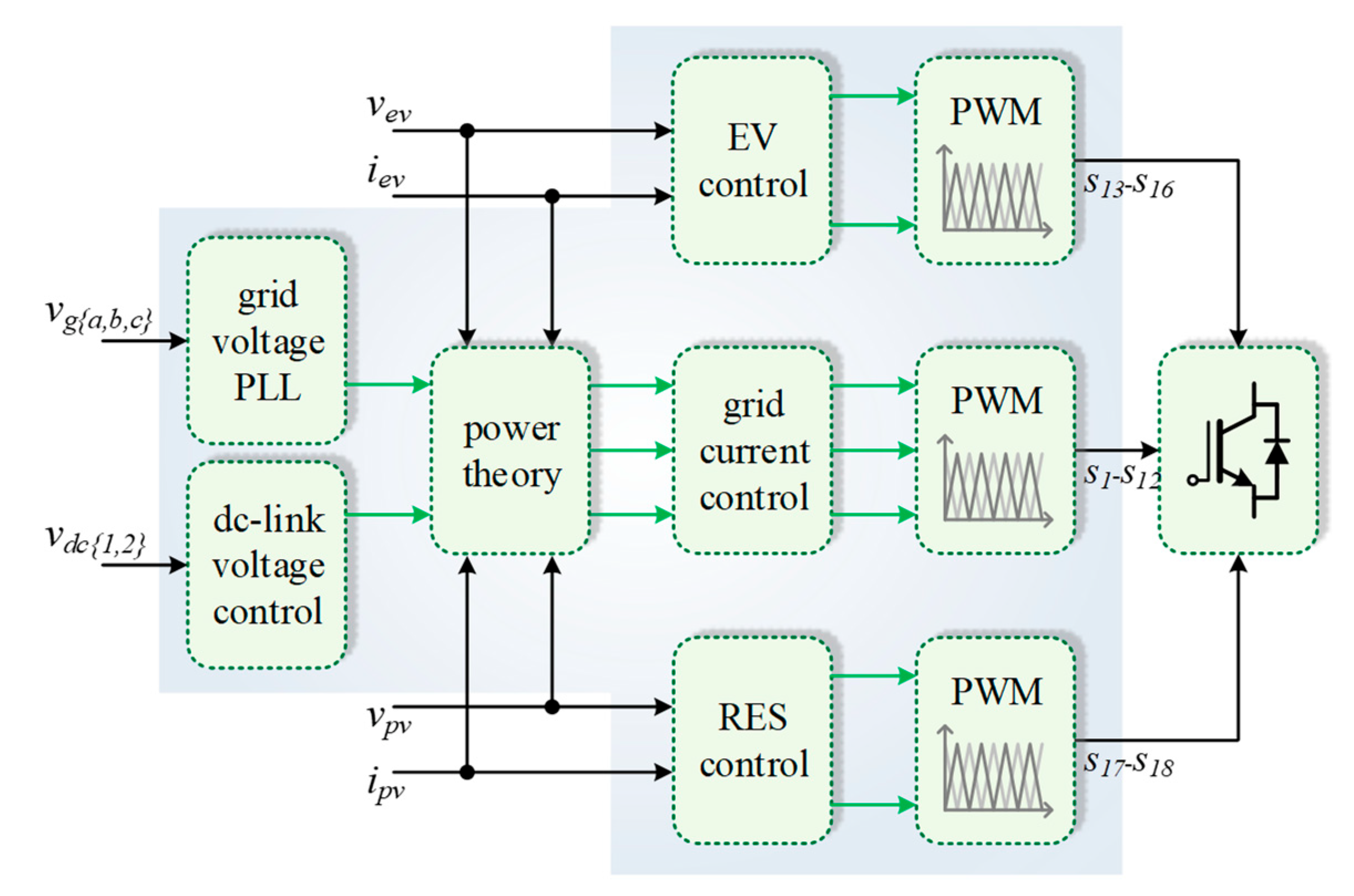
3. Control Algorithms for the Unified Topology
At the control level, as mentioned in
Section 2, the AC and DC interfaces can be individually controlled with a specific algorithm, but contemplating that the operation of one of the interfaces can influence the operation of another.
Figure 3 presents a general structure of the control algorithm, considering the control of the entire unified topology, as well as the different possibilities of interconnected operation between the various technologies: EV, RES, and power grid. As shown in this figure, a power theory is necessary for establishing the references of current for the AC-side, which receives as input the variables from the DC-side, as well as from the DC-link and from the power grid voltage. Specifically, it is possible to verify that a phase-locked loop (PLL) algorithm is considered, instead of the real measured voltages. This is fundamental to ensure that the references are sinusoidal and not dependent of the harmonic distortion or unbalances presented in the voltages.
The AC-side is controlled considering two distinct and necessary approaches: in terms of AC currents and in terms of voltage on the DC-link. The current control is carried out independently of the reference waveform, which is fundamental to ensure that the unified topology can operate with the highlighted modes, mainly in terms of currents with harmonics for the power grid side in a smart grid contextualization of operation. Based on the analysis of voltages and currents on the AC-side of the unified topology, and considering a digital implementation using a forward Euler discretization method, the equation that relates the voltages and the currents is defined by:
This equation allows to control the AC currents (
ig{a,b,c}) in each of the phases and independently of the reference (
ig{a,b,c}*). Moreover, it should be noted that different references can be used for each phase and the current control must be able to follow such references. The variable
vUT{a,b,c} is the one that is compared with the pulse-width modulation (PWM) carrier to obtain the control signals for the IGBTs of each phase. Distinct PWM carriers are used to guarantee the interleaved operation. As the AC-side interface is based on an interleaved structure per phase, then it is necessary to individually control the current in each leg of each phase. Clearly, each
vUT{a,b,c} variable is compared with the respective PWM carrier. The reference of current for each leg of a given phase must be the same to guarantee the correct interleaved operation, only differing the PWM carrier. Otherwise, the ripple of the resulting current in each phase is not properly minimized (e.g., when the duty-cycle is 50%, the current ripple is necessarily canceled on the resultant current). When the unified topology operates only with active power, the amplitude of the AC currents is directly related to the operating power on the DC-side and must be in phase or in phase opposition with the fundamental component of each voltage. Therefore, a relationship between the currents, voltages and operation power must be established, resulting in a reference of current for each phase (
ig{a,b,c}*) according to:
where
corresponds to the average value of the necessary power to ensure that the DC-link voltage is properly controlled,
pEV corresponds to the instantaneous operating power of the EV,
pRES corresponds to the instantaneous operating power of the RES, and
Vg{a,b,c} and
vg{a,b,c} correspond, respectively, to the root mean square (RMS) value and to the instantaneous value of the power grid voltages of each phase. Based on the position of the current sensor on the EV interface, the value of
pEV will assume positive or negative values, then the references of current (
ig{a,b,c}*) will be in phase or phase opposition with the voltages. Consequently, since each phase operates in interleaved mode, the reference of current for each leg of each phase (
ig{a,b,c}{1,2}*) is defined according to:
The previous equations are used to control the current on the AC-side when the unified topology only operates with active power in bidirectional mode. As mentioned, for the AC-side, the amplitude of the currents is directly influenced by the operating power. As an important feature of the proposed unified topology, the possibility arises to operate with reactive power and harmonic currents. These two additional possibilities can be controlled individually and can be combined, or not, with the normal bidirectional operation of the unified topology in terms of active power. Therefore, the references of current for the AC-side (
ig{a,b,c}*) must be defined by also considering such possibility (i.e., non-sinusoidal references), and not influencing the control defined by Equation (1), which permits to control the AC-side currents individually and independently of the waveform and frequency. More specifically, for producing reactive power, a signal in quadrature must be considered, which can be obtained from the PLL. The value of reactive power, as well as the period for the unified topology operating in such mode, must be provided by the smart grid. Nonetheless, it is essential to mention that the focus of this paper is to introduce the unified topology and its control, not the smart grid management strategy in terms of defining the reference of reactive power for the unified topology. Therefore, the scope of this paper only has proven the operation of the unified topology considering exemplificative scenarios of a smart grid contextualization. By assuming such considerations, the references of current (
ig{a,b,c}*) are defined by three distinct parts, related with the bidirectional operation with active power (as previously demonstrated by Equation (1)), the operation with reactive power, and the operation with harmonic currents. Thus, the digital implementation of the equation that defines the references of current for each phase of the unified topology is given by:
where
vg_cos{a,b,c} corresponds to the quadrature signals obtained from the PLL,
Q* corresponds to the value of reactive power that the unified topology must produce per phase,
igh[
k] corresponds to the harmonic order (which is taken from a PLL), and h corresponds to the amplitude of the harmonic that must be produced. This is the global equation that must be used to control the AC-side currents, but, obviously, depending on the assumed values on the DC-side and the values of the reference for the reactive power and for the harmonics, other equations are derived.
The interfaces on the DC-side of the unified topology have the same principle of operation in terms of controllability and multilevel and interleaved features, only differing the values of current and operating voltage of each technology. Specifically, for the operation in current control mode when power is injected into the DC-link, according to the indication of voltages and currents, the control equations for the interfaces of the EV and RES are defined as:
where the variables
vUTEV and
vUTRES are compared with the respective PWM carriers. Since the unified topology has a midpoint on the DC-link, the operation with different voltage levels is possible, depending on whether the voltage on the technology side is less than, equal to, or greater than half the voltage on the DC-link. This feature is very important, as it ensures that each of the IGBTs only operate with half of the voltage of the DC-link, regardless of voltage and current levels on the interfaces of EV or RES, as well as the mode of operation.
On the other hand, for operation in current control mode, when power is absorbed from the DC-link, only the EV interface operates in this mode (i.e., the EV charging process), since the RES only injects power to the DC-link. This operation and current control is independently of the power source, i.e., it is independently if the EV is charged with power from the RES or from the power grid since the objective is only to perform the current control on the EV interface. Therefore, according to the indication of voltages and currents, the control equation for the EV interface is defined as:
where the variable
vUTEV is compared with the respective PWM carrier. The operation principle is the same as previously presented, only differing the direction of the power flow. For each operating mode, the reference of current is defined by the state of the EV, i.e., it is established by the internal control system of the EV, as well as the maximum power that can be extracted from the RES.
As outlined earlier, the purpose of this paper is to introduce the structure of the unified topology, its principle of operation, and respective control equations for all possible modes, and validate the interconnected operation for different operating conditions; thus, the smart grid power management strategy is outside the scope of this paper. In addition, the operating conditions and interdependence of all the technologies involved are numerous, and their full validation in a single paper is not possible; therefore, only the main operating conditions are considered for validating the proposal of this paper.
4. Unified Topology: Computer Simulation and Experimental Validation
This section presents the validation of the proposed unified topology, encompassing the cooperative and individual operation of both the AC and DC sides.
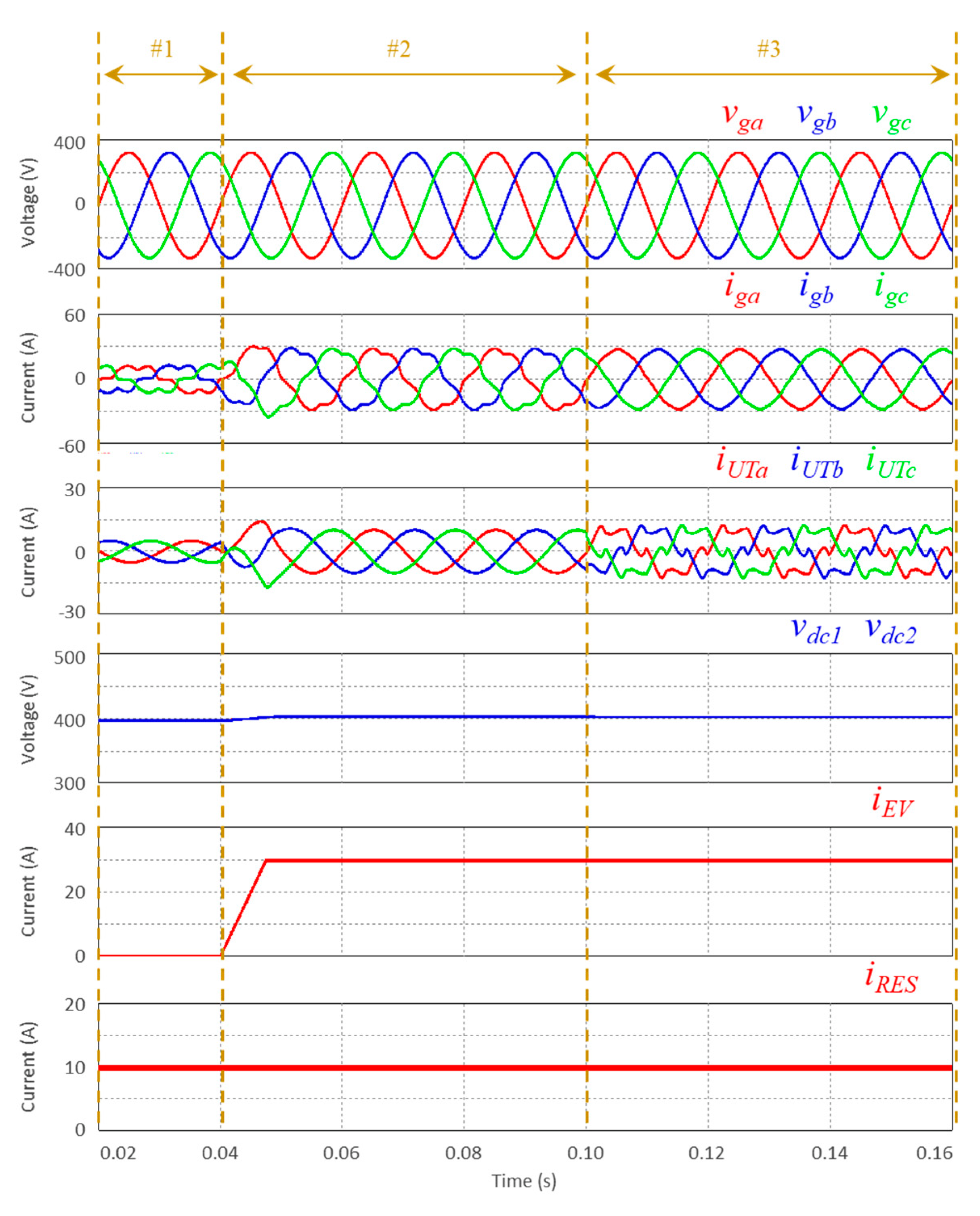
Figure 4 shows a result obtained with the PSIM v9.3 software that validates the proposed unified topology, considering the integration and dynamic operation of each interface on AC and DC sides. Clearly, another operation sequence for each mode could have been considered, without affecting the operation of the entire unified topology in the slightest, i.e., by changing the operation sequence or the operating power of each of the interfaces would in no way affect the validation of the unified topology in terms of operation. This sequence of operation was considered since it perfectly illustrates the main operation modes allowed by the unified topology.
This figure shows the instantaneous values of the voltages (vga, vgb, vgc) and currents (iga, igb, igc) on the power grid, the currents at the AC-side of the unified topology (iUta, iUtb, iUtc), the voltages on the DC-link (vdc1, vdc2), the currents on the DC-side of the unified topology, namely the current on the EV interface (iEV), and the current on the RES interface (iRES). During case 1, only the RES is producing power, while the EV is turned off. In this case, all the produced power is clearly injected into the power grid, characterized by balanced and sinusoidal currents in opposition to the voltages. On the other hand, during case 2, the EV starts the charging operation, which is characterized by the increasing power consumption from the power grid, since the power production from the RES is not enough to supply all the power required by the EV charging. Therefore, this case reports a situation of EV charging with power both from the power grid and from the RES. As it can be observed, the operating currents on the AC-side of the unified topology (iUTa, iUTb, iUTc) are balanced and sinusoidal, but, since it is absorbed power from the grid, in case 2, the currents are in phase with the voltages. From the power grid point of view, case 2 (absorbing power) is quite different from case 1 (injecting power). As expected, the DC-link voltages are controlled based on the established reference situation that is independent of the operating case. Consequently, in case 3, the AC-side of the unified topology starts to compensate for the power quality problems introduced by the loads that are connected at the same point of connection to the power grid. In this case, in the sequence of the previous cases (the EV and the RES maintain the same operation as in case 2), no additional active power is exchanged with the power grid, but the AC-side of the unified topology stops operating with sinusoidal currents, while the DC-side of the unified topology maintains the same operation (meaning that the EV charging power is the same and the power produced by the RES is also the same as reported in case 2). In this way, the control algorithm for the AC-side only changes to ensure that the currents of the unified topology (iUTa, iUTb, iUTc) are distorted to compensate for the harmonic distortion caused by the loads connected in the same installation. As consequence, sinusoidal and balanced currents on the power grid side (iga, igb, igc) are obtained. This result shows, in a global way, the principle of operation of the entire unified topology, highlighting the main functionalities when analyzed in terms of controllability. The unified topology start operating sequentially until the limit case in which all the possibilities are operating at the same time and complying with the full functionality. Clearly, as previously mentioned, the sequence of operation can be modified according to the different possible cases since this result is only intended to assess a concrete example.
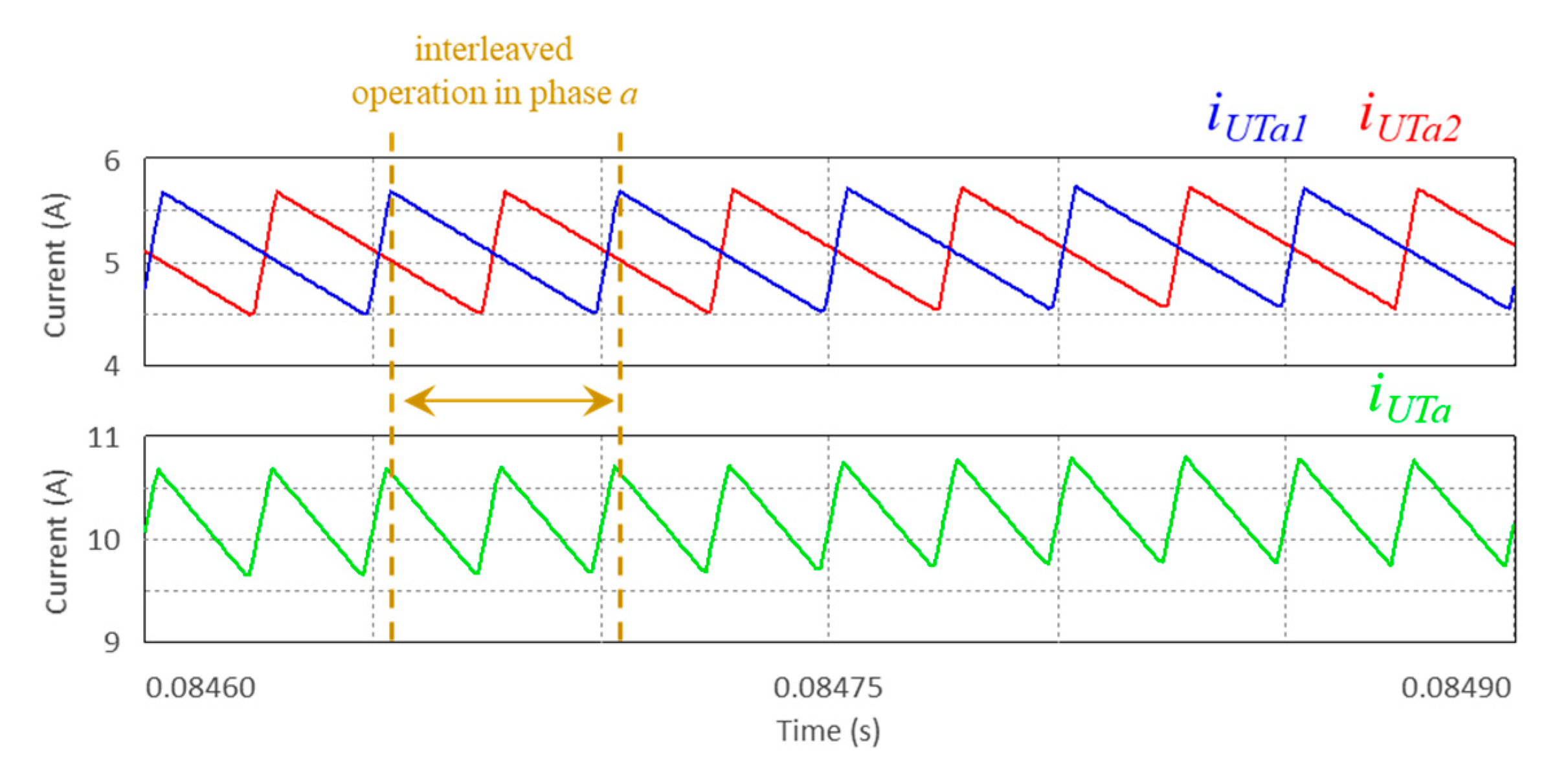
Specifically for phase
a,
Figure 5 shows the phase current (
iUTa), as well as the currents (
iUTa,
iUTb) on each leg of this phase. Since these currents are presented in detail, the interleaved operation is highly visible, characterized by the currents
iUTa and
iUTb in phase opposition, and by the current
iUT that is the sum of the currents
iUTa and
iUTb. Consequently, the current
iUTa presents a ripple with a frequency that is the double of the switching frequency (i.e., the double of the ripple frequency of the currents
iUTa,
iUTb).
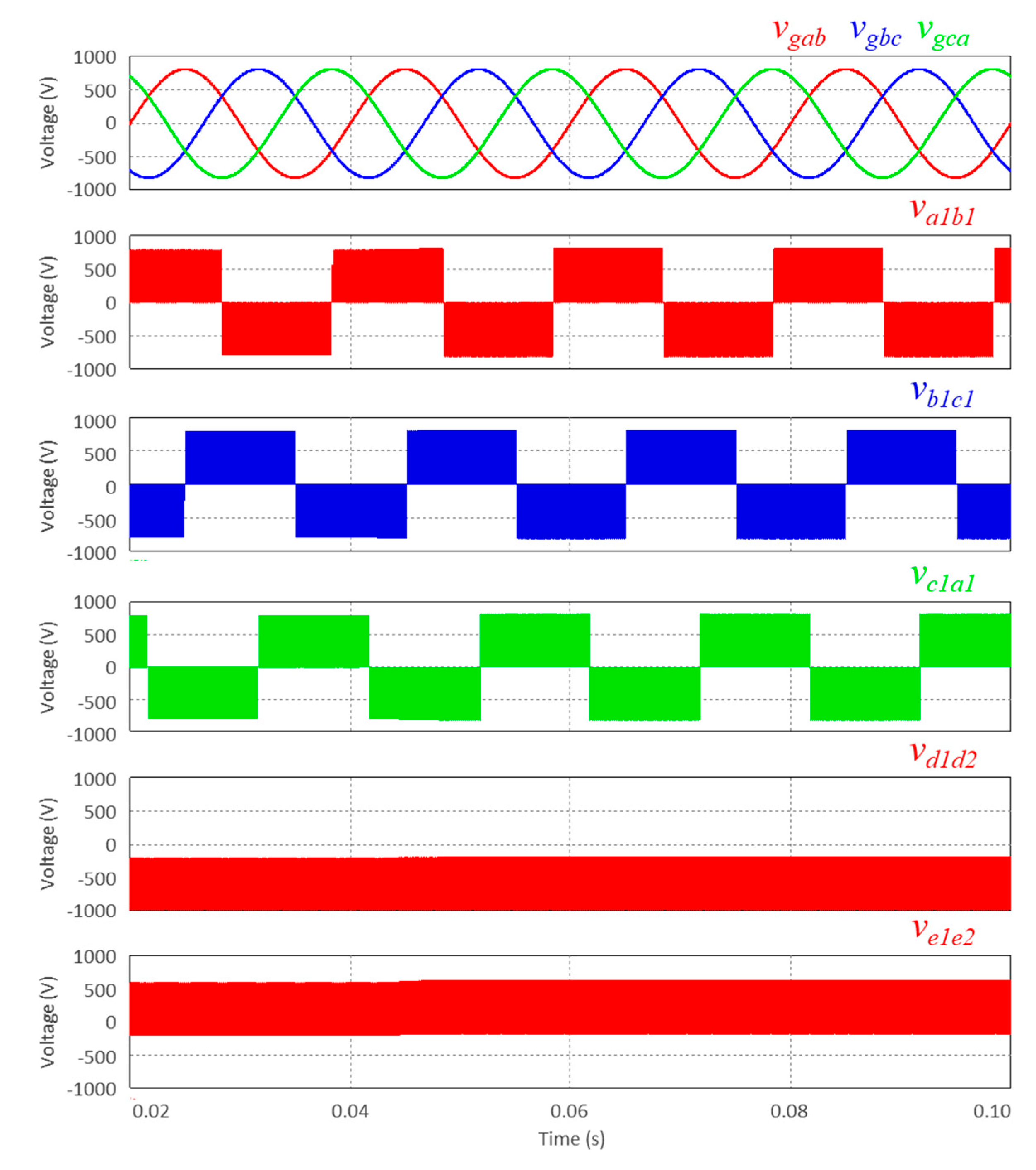
Figure 6 shows the power grid phase-to-phase voltages (
vgab,
vgcb,
vgca) and the voltages of the unified topology on both AC-side (
va1b1,
vc1b1,
vc1a1) and DC-side (
vd1d2,
ve1e2). The voltages on the AC-side (
va1b1,
vc1b1,
vc1a1) assume the possible three voltage levels (+
vdc, 0, −
vdc), are balanced and are in phase with the respective phase-to-phase voltage (
vgab,
vgcb,
vgca). On the other hand, the voltages on the DC-side (
vd1d2,
ve1e2) assume the three voltage levels. In the case of the interface of the EV, in this specific case, it is shown that the voltage assumes the values of 0 and
vdc/2, while in the case of the interface of the RES, in this specific case, it is shown that the voltage assumes the values of
vdc/2 and
vdc. The assumed values on each DC-side can be different, depending on the voltage on the DC interfaces as well as the voltages on the DC-link.
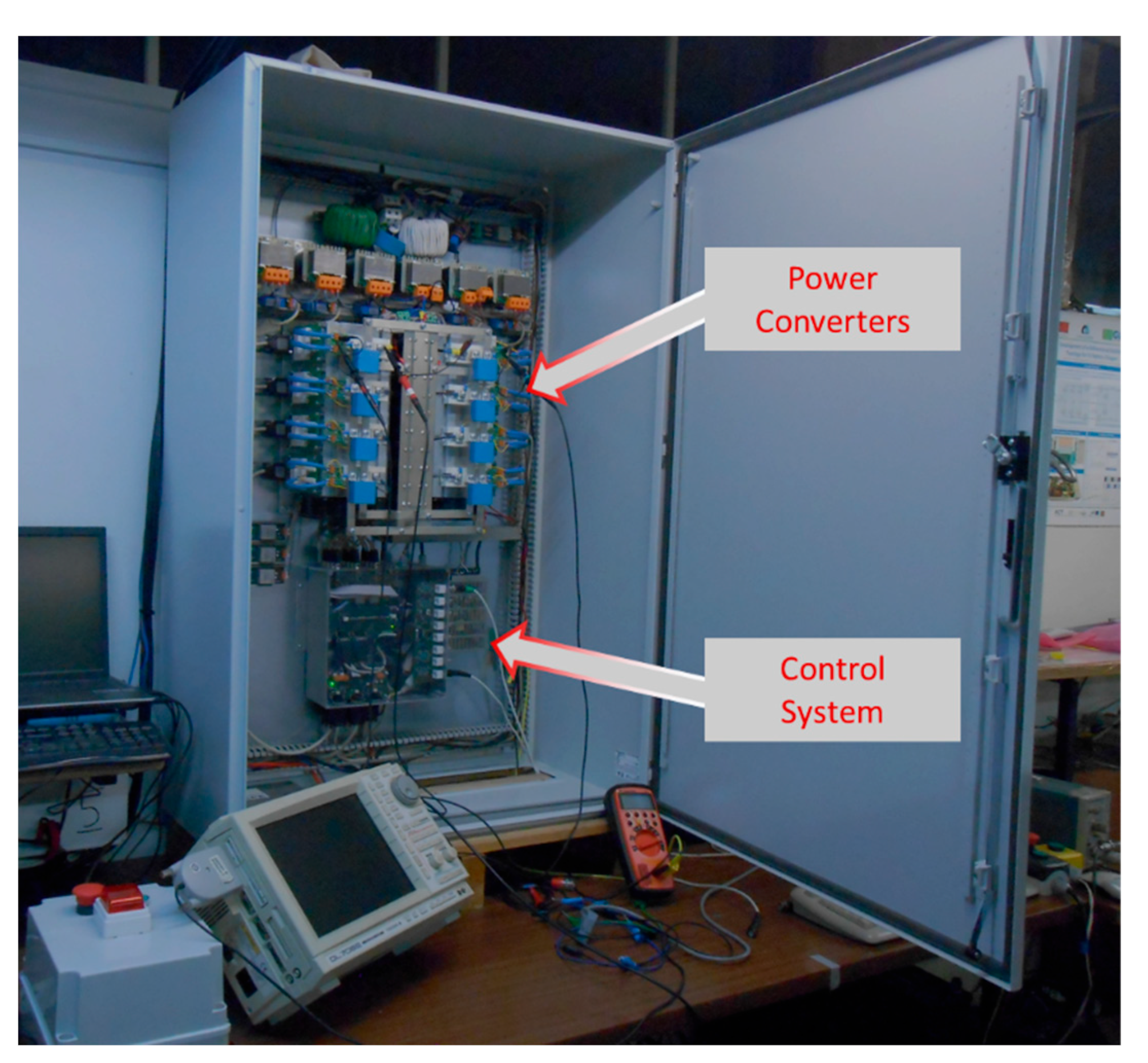
In terms of experimental validation,
Figure 7 shows the laboratory prototype used for the experimental validation, highlighting the power converters and the control system. For voltage and current measurement, voltage transducers CYHVS025A and current transducers LA 100 P were used. A signal conditioning circuit was used to interface such transducers with the internal analogue-to-digital converters (ADCs) of the digital signal processor (DSP), programmed for a sampling frequency of 40 kHz. A DSP TMS320F28335 was used. IGBTs SKM100GB125DN and drivers SKHI22AH4R were used. A switching frequency of 20 kHz was considered for each IGBT of each leg.
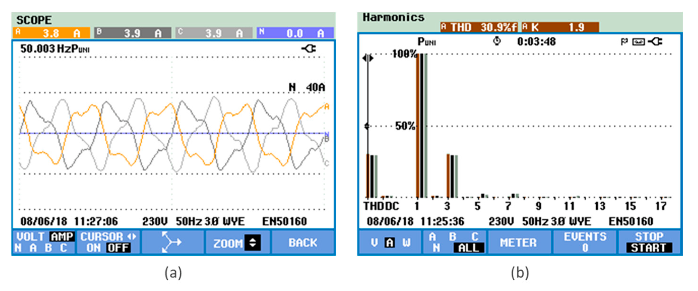
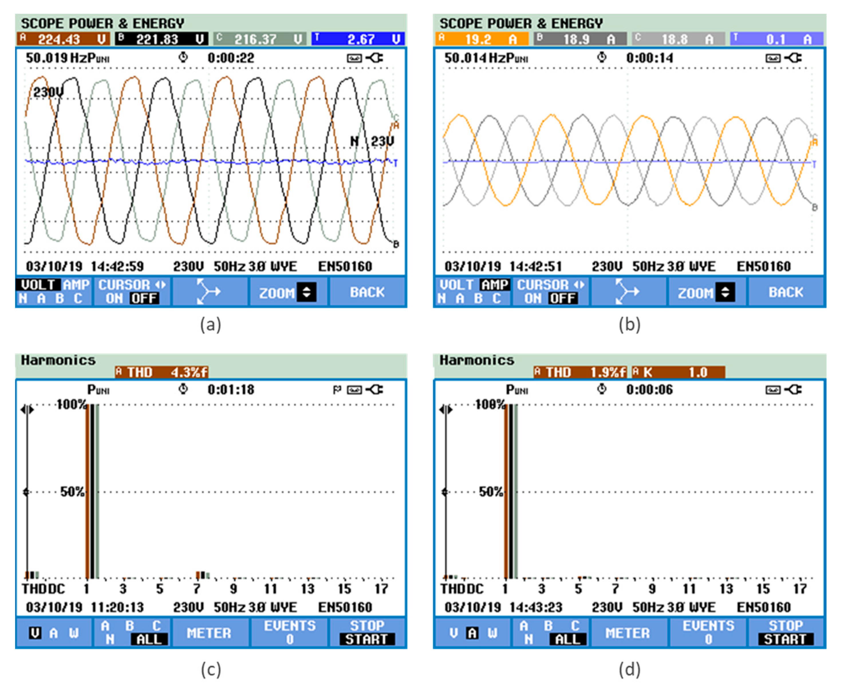
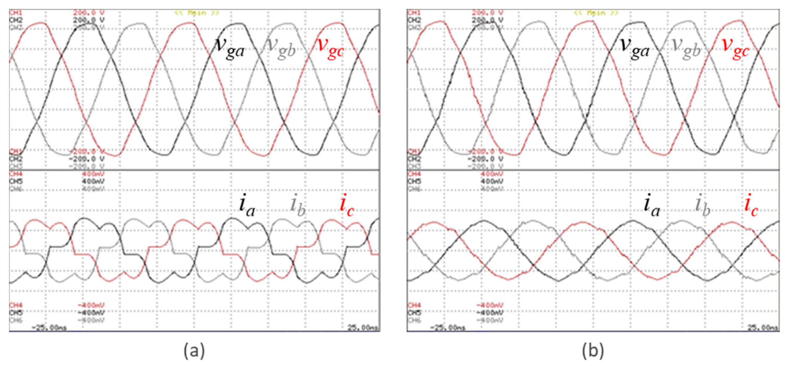
Figure 8a,b shows the voltages and currents on the AC-side, respectively. In these results, it is visible that the currents present are balanced and have a sinusoidal waveform, which is advantageous in the perspective of not accentuating power quality concerns for the power grid. For these same voltages and currents,
Figure 8c,d shows the harmonic spectrum and the total harmonic distortion (THD) value, respectively, showing the values of 4.3% and 1.9%. These results were obtained with a power grid voltage of 400 V-50 Hz (phase-to-phase voltage), a voltage on the DC-link of 800 V, and for an operating power of 12.5 kW. It is crucial to highlight that these results were obtained with the unified topology directly connected to the power grid.
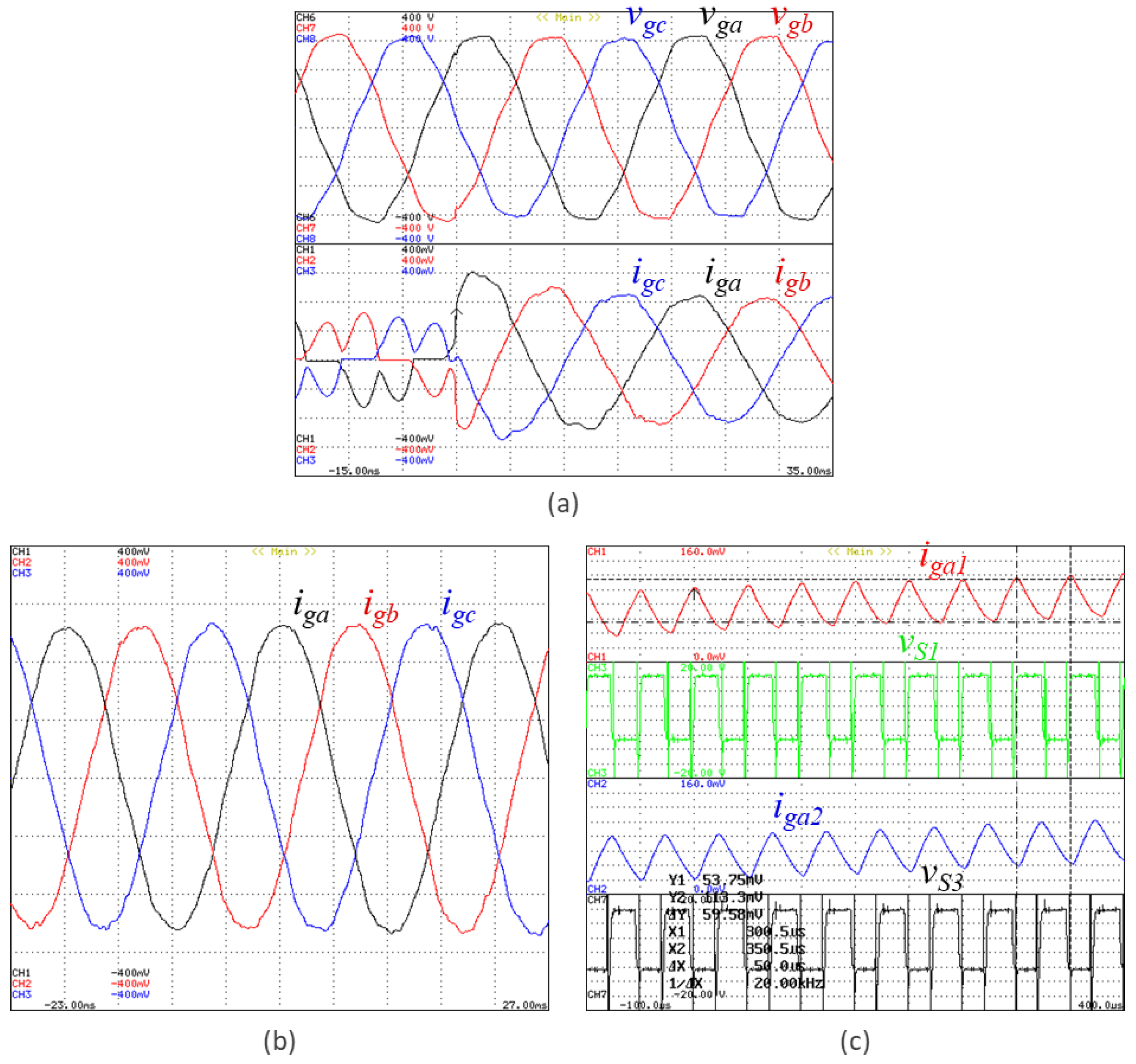
Figure 9 shows the voltages and the currents on the AC-side, in detail and in a transient-state.
Figure 9a shows the currents on the AC-side in two different situations: (i) Before starting with a controlled operation, i.e., the interface operates as a diode rectifier, where the IGBTs are not being controlled; therefore, the AC-side currents are not controlled and the DC-link voltage is also not controlled; (ii) After starting with a controlled operation, i.e., operating, as expected, as a three-phase active rectifier, controlling both the AC-side currents and the DC-link voltages. As can be seen, before starting with a controlled operation, despite the power being transferred to the DC-link, the currents are not sinusoidal. Later, when starting with a controlled operation, the currents become sinusoidal. For such a situation to occur, the voltage on the DC-link is increased, which is reflected in the increase in the currents at the input, without causing any disturbance in the power grid. In this result, while the currents are controlled on the AC-side, the power also increases due to the EV on the DC-side, which is visible on the currents’ waveforms. The currents in steady-state are shown in
Figure 9b, proving the characteristics previously highlighted: balanced and sinusoidal currents. Finally, in
Figure 9c, starting from the example of phase
a, the currents in each leg and the resulting current are shown. The currents in each leg present the necessary opposition in terms of the ripple waveform for the operation in interleaved mode, and the resulting current, which corresponds to the sum of the currents of the two legs, presents a smaller ripple whose frequency corresponds directly to twice the switching frequency, validating the operation in interleaved mode.
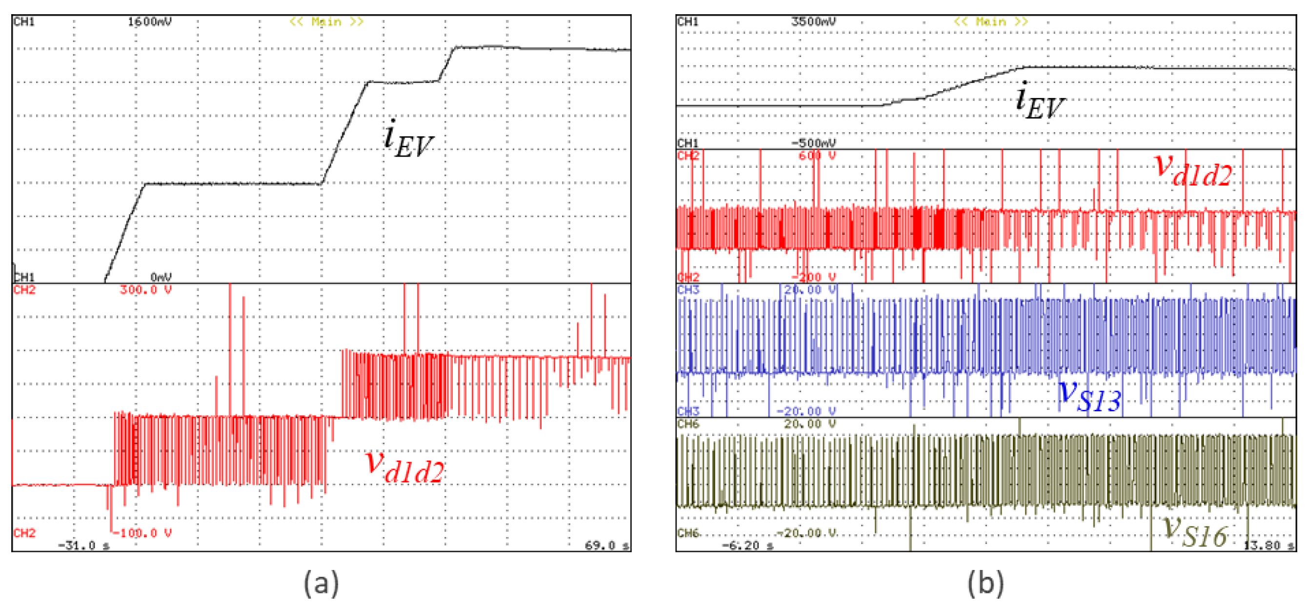
Figure 10 shows a result specifically regarding the EV interface.
Figure 10a demonstrates one of the functionalities of the unified topology in the DC-side: the possibility to operate in multilevel mode with three voltage levels. In this case, as can be verified, the interface assumes the three voltage levels according to the charging current of the EV. As the charging current increases, the voltage also increases; therefore, the voltage in the EV interface changes in relation to the DC-link voltages, forcing the unified topology to operate with different voltage levels (voltage
vd1d2 measure in the points
d1 and
d2 represented in
Figure 2). A particular case occurs when the voltage of the EV interface is equal to half of the DC-link voltage, resulting in a current with a null-ripple. In this case, it is necessary to control the DC-link to guarantee that both voltages are balanced. In this sense,
Figure 10b shows the same variables, as well as the gate-emitter voltages of the IGBTs
S13 and
S16, to verify the relationship of the variation between the IGBTs duty-cycle with the voltage of the unified topology (
vd1d2) and with the EV current (
iEV).
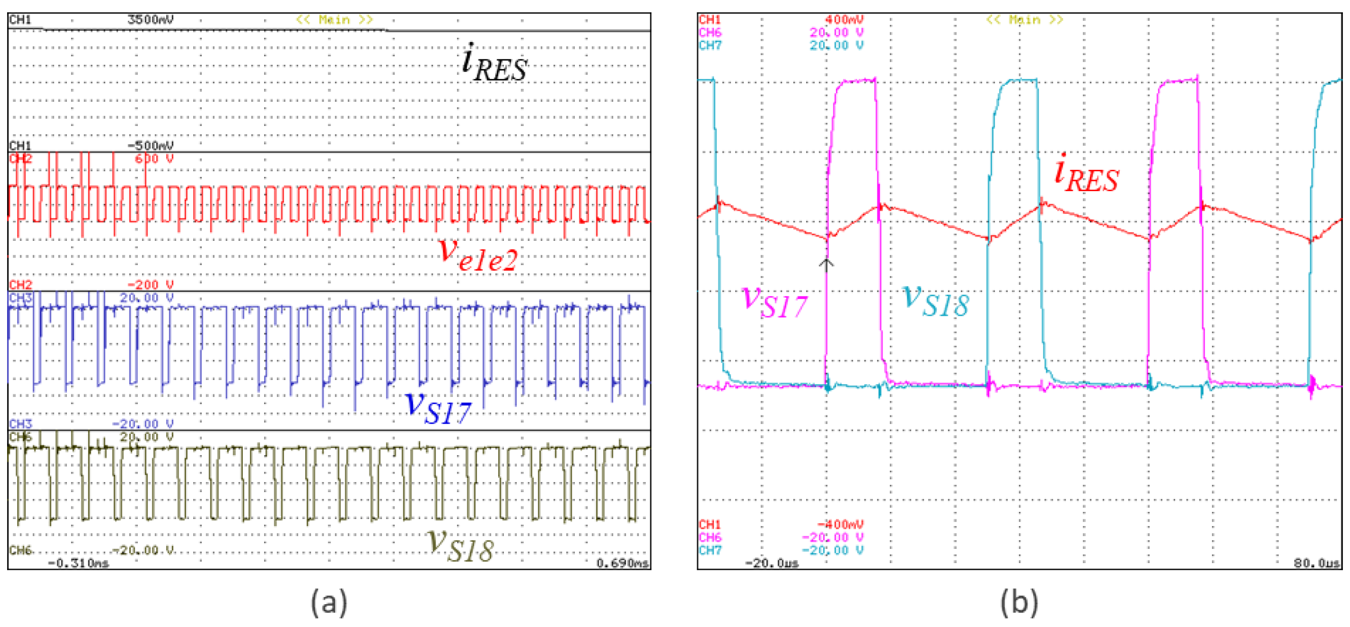
Figure 11 shows a result specifically regarding the RES interface. In this case, such interface operates in boost mode, but guaranteeing the operation with the three voltage levels, which are also dependent of the voltage level of the RES interface.
Figure 11a shows in detail the current on the RES interface, the voltage of the unified topology in the RES interface, as well as the gate-emitter voltage of the IGBTs
S17 and
S18. Analyzing the gate-emitter voltages, it is possible to verify that they are controlled in phase opposition aiming to guarantee the interleaved mode also on the RES interface. Additionally, as the voltage in the RES interface (voltage
ve1e2 measure in the points
e1 and
e2 represented in
Figure 2) is higher than half of the DC-link voltage, the voltage of the unified topology changing between two levels, namely half of the DC-link voltage and the full DC-link voltage, is presented. Similar to the EV interface, it is possible to eliminate the current ripple when the voltage of the RES is equal to half of the DC-link.
Figure 11b demonstrates the relationship between the current on the RES interface and the gate-emitter voltage of the IGBTs
S17 and
S18.
Figure 12 shows a result that validates the operation of the unified topology to inject a third harmonic current to contribute to compensate power quality problems. This result allows to see when the unified topology is operating with distorted currents. In this situation, it operates with the injection of a third harmonic current. This situation is particularly relevant for a contextualization with smart grids, where the unified topology can be controlled for producing harmonic currents with the objective to help to compensate power quality problems.
Figure 13 shows a result that validates the operation of the unified topology performing the compensation of harmonic currents and power factor, caused by the nonlinear loads connected in the same electrical installation. This result was obtained with the unified topology only operating to compensate the harmonic currents; therefore, there is not an active power exchange between the AC-side and the DC-side. As can be verified in the situation reported in
Figure 13a, before the operation of the unified topology, the currents on the power grid side are characterized by a non-sinusoidal waveform. Nevertheless, as expected, when the unified topology is controlled for compensating such non-linear behavior, the currents on the power grid side become sinusoidal, as the situation is presented in
Figure 13b. This situation is totally different from the situation reported in
Figure 12, since in this case the unified topology is controlled for compensating all the harmonic currents, and not only a specific harmonic current. Evidently, in a context fully integrated in smart grids, these modes of operation are managed by the smart grid itself, considering the operational limits of the unified topology (i.e., according to the nominal values of voltage and current).
5. Discussion
A three-phase unified topology, which permits a collaborative operation with the integration of a renewable energy source (RES), an electric vehicle (EV), and the compensation of power quality problems in the power grid, is presented in this paper. Therefore, a key contribution of this paper resides in the fact that only an interface with the power grid is necessary to involve three central features of smart grids: renewables, electric mobility, and power quality. The proposed three-phase unified topology allows several operation modes, not only limited to the interface of the RES, EV, and power grid. The contextualization of the proposed unified topology, connected in a perspective of smart grids, is demonstrated along with the paper, and the main differentiating features are compared with the conventional structures. In the state-of-the-art, there are other available unified structures, but not encompassing all the features proposed in this paper, as is clearly presented in the introduction section, supported by a comparison with the most relevant references. The proposed three-phase unified topology permits the EV and RES interface with the power grid, i.e., specifically, it is possible to: (i) Inject power into the power grid from the RES, independently of the variable power production; (ii) Establish bidirectional power operation between the EV and the power grid, with a three-phase interface, ensuring the grid-to-vehicle (G2V) and vehicle-to-grid (V2G) modes. Moreover, as a contribution of this paper, these modes can also contemplate the possibility of operating as an active power filter, without neglecting the interface features of the EV and RES with the power grid. In this way, as validated in the paper, it is possible to interface the RES or the EV with the power grid and simultaneously contribute to improving power quality through the unified topology and proposed algorithms. Another relevant contribution is the possibility of directly interfacing the RES with the EV, without using the power grid as an intermediary. This is extremely important in terms of optimization, since the number of power conversions is much more reduced when compared with the traditional solution (i.e., the interface from RES to the EV is only performed in DC). When the EV is not presented and does not produce power from the RES, the proposed three-phase unified topology can operate only for interfacing the power grid with active power filtering, improving the power quality, which represents another relevant contribution, since with the traditional solutions, when the EV is not plugged-in to the off-board charging system, the power electronics is not used for anything else.
The proposed structure of the unified topology has been presented, consisting of a three-phase four-wire topology on the AC-side, based on an interleaved structure for each phase, and two DC-sides for interfacing the EV and RES. The proposed topology presents important advantages over traditional solutions, specifically in the reduction of the current ripple. The midpoint on the DC-link is fundamental to connect the neutral wire, and, consequently, for the active power filtering operation. The proposed unified topology permits the operation with sinusoidal and balanced currents on the AC-side, or with programmed distorted currents (for harmonics compensation) during the active power filtering operation. The general structure of the control algorithms for the unified topology is presented its specific section, where details are presented on the whole control of the unified topology, as well as the diverse opportunities of interrelated operation among the various technologies, i.e., EV, RES, and power grid. For all operating modes, a power theory is considered for determining the references of current for the AC-side. This power theory receives the variables from the DC-side, as well as from the DC-link. In the control algorithm, a PLL algorithm is considered, ensuring that the references are purely sinusoidal. The current on the AC-side is controlled for any reference waveform, permitting the operation according to the distinct modes, including the possibility of operating with the production of current harmonics for active power filtering.
PARÁGRAFO, a laboratory prototype, was developed for the experimental validation, including all the circuits necessary for the hardware and software systems. All the circuits were specifically developed in laboratory for his prototype, and all the control algorithms were programmed in the DSP of the control system, with C code, using the Code Composer Studio, from Texas Instruments. The fact that everything was developed in the laboratory is an asset for the identification of errors, and for adjusting the control algorithms, since it is possible to have control over all variables in real time. The experimental validation demonstrates the correct operation of the unified topology and the advanced proposed features. The experimental results show the proposed unified topology operating with sinusoidal and balanced currents, which is fundamental to avoid contributing to deteriorating power quality problems. However, as a differentiating contribution in this paper, when required by the power grid for specific management strategies from the power grid point of view, the proposed unified topology can operate to inject specific harmonic currents, in order to compensate harmonic currents in the power grid side. This innovative option can be implemented independently of the operation to interface the EV or RES (i.e., it can be performed at the same time, or not). Moreover, if necessary, the proposed unified topology can be controlled for compensating almost all harmonic currents at the same time, contributing to the compensation of power quality problems on the power grid side. This is also a relevant and differentiating contribution in this paper.
Despite the significant added value presented in this paper, this topic is not completely closed, and new advances can be achieved. Particularly noteworthy is the integration of more EVs through the proposed unified topology, creating a DC grid for multiple off-board EV charging stations. Additionally, another important feature that can also be considered in the sequence of this paper, is the integration of energy storage systems, allowing for advanced operating perspectives that include production from renewables, the management of power grid demand, and the charging of EVs. In order to implement these perspectives, it will be necessary to develop and implement a depth of reformulation on the control algorithms as they apply to the operation of the unified topology, e.g., the EV can be charged from the power grid from the RES or from the energy storage system, and the power production from RES can be injected into the power grid, can be used to charge the EV, or can be stored for further use.
6. Conclusions
This paper proposes a three-phase unified topology with a unique AC-side interface and two DC-side interfaces, allowing a collaborative integration and operation among the interfaces, while it can also offer active filtering capabilities for the power grid. The unified topology is possible since the linked technologies on the DC-side, i.e., an electric vehicle (EV) and a renewable energy source, have a DC connection in common, converging to a solution with a unique interface with the power grid, without impairing the functionalities and added values of each technology. The principle of operation of each interface is presented, as well as the respective control strategy. The overall control algorithms of the proposed unified topology are presented in detail for all the possible modes of operation, together with the various prospects of interrelated operation among the technologies. Specifically, the power theory and the current control for both AC-side and DC-side has been presented. From the power grid point of view, the proposed control algorithm for the operation with any reference waveform, i.e., ensuring the operation with balanced and sinusoidal currents, as well as the possibility of producing current harmonics as a contribution to improve the power quality on the power grid side, has been presented. Regarding the DC-side, it was possible to verify the correct operation, highlighting the most relevant characteristics in terms of multilevel and interleaved features. It was also possible to verify the correct functioning at the AC-side, highlighting sinusoidal and balanced currents when receiving power from the power grid, or with currents that present harmonic content to compensate these same harmonics of the power grid, thus contributing to improving the power quality, in a perspective of a collaborative operation within smart grids. It is important to highlight that, as verified, the operation with currents with harmonic content on the AC-side does not affect the operation of the technologies on the DC-side, because active power was not exchanged between the power grid and the DC-link. The experimental results were obtained using a developed laboratory prototype, including all the circuits related with the hardware and software, confirming the correct operation and advantages of the presented three-phase unified topology. In a future perspective, by maintaining the same features of the proposed unified topology, the study can be extended with a possible integration of more EVs, as well as the for a possible integration of energy storage systems, thus, offering advanced operating perspectives for power grid management in terms of power production, storage, and consumption.


