Abstract
The energy transition towards renewable energies is crucial for the sustainable development of a society based on hydrocarbons. The current level of penetration and growth of wind energy in electric power systems is evident and many researchers have presented new methods for simulating and representing the electrical and mechanical characteristics of variable-speed wind turbines. However, complete mathematical models developed and implemented, for example, in MATLAB/Simulink® software, require significant computational efforts that could make grid studies impractical when its scale tends to increase. To contribute to facing this issue, this paper proposes an extended simplified model for a variable-speed wind turbine that considers the dynamic behavior of its mechanical system and includes an approximate representation of the power electronic converter. This approach broadens the scope of studies related to grid frequency control and power quality (fast-frequency response, primary frequency control, and voltage control, among others), considerably reducing the computational burden. Several validations of the proposed simplified model are presented, including comparisons with a doubly fed induction generator-based wind turbine model (phasor type) from the MATLAB/Simulink® library, and laboratory experiments under controlled conditions. The results show a good fit of the proposed simplified model to the MATLAB/Simulink® model, with minimal delays about 3% of the wind turbine inertia constant. Moreover, with the proposal, the computational time is reduced by up to 80% compared to a detailed model. This time reduction is achieved without penalizing the numerical accuracy and the estimation quality of the real behavior of the variable-speed wind turbine.
1. Introduction
The generation of renewable electrical energy has undergone an important development to face the global climatic crisis [1,2]. The remarkable growth of wind power (WP) initiates a transition phase based on large-scale energy efficiency [3]. During 2021, new WP installations reached 94 GW worldwide, reaching a cumulative installed capacity of 837 GW, which represents a growth of 12% compared to 2020 [4]. Most wind turbines (WT) installed are variable-speed wind turbines (VSWT) based on either the doubly fed induction generator (DFIG) or the synchronous generator via full converter (SGFC), due to their versatility and efficiency [5]. However, the intermittent nature of the wind resource is an important factor in the technological development of WTs [6]. For example, the conventional response of a VSWT to possible disturbances in the power system, such as a frequency deviation caused by an imbalance between electric generation and demand, does not include the natural contribution of its inertia to provide support, as a conventional synchronous generator would [7]. In the research for solutions to these drawbacks, many authors have chosen to simulate the DFIG-WT in the MATLAB/Simulink® environment, whose models are highly robust. However, studies that involve many WTs and their interactions with the electric power system lead to complex problems with many different components characterized by very diverse time scale dynamics. Particularly, the detailed modeling of the power electronic converter (PEC) of each WT in a larger system leads to a multiscale problem that requires so high a computational effort that it is almost intractable with conventional modeling approaches. Therefore, studying efficient methods that manage to reduce the computational burden without compromising the accuracy of the dynamic model of the VSWT and PEC is necessary.
In the literature, various studies have shown the possibility of acting on the sophisticated control system of a WT to provide a wide range of ancillary services [8]. In this context, detailed VSWT models have been developed. In ref. [9], the authors model the DFIG to investigate the contribution of a WT to the power system frequency control. Mainly, the impact of the different regulator settings and the system inertia are investigated and the results are evaluated from a computational point of view. In [10], the authors model a variable-speed wind system based on a DFIG with a linear PI controller, with the stator connected directly to the grid and the rotor connected through a back-to-back converter. The results are evaluated in a simulation environment where a refinement depends on the computational robustness implemented. The MATLAB software presents a sophisticated DFIG modeling, as mentioned in ref. [11], where the WT is simulated with the Wind Energy Conversion System (WECS), using the maximum power point tracking (MPPT) method to extract the optimal power and applying the Backstepping controller to control reactive power and electromagnetic torque in order to test the performance and robustness of the system. The results show a great precision in the behavior of the WT with respect to the datasheets. However, MATLAB simulates the entire WT system and is not segmented, which is inefficient for certain specific VSWT applications. In this sense, the authors have proposed new WT-DFIG modeling methods focusing on the parameters under study. For example, in [12], the derivation of the mathematical model of a WT is based on formulas that calculate the mechanical and electrical power of the WT, the results showing that the proposed model is simple with low computational burden. However, the model can only be applied in voltage control mode—though the model of several DFIGs connected to the grid (e.g., with hundreds of buses) is a significant computational challenge [13]. Similarly, ref. [5] presents a detailed simulation model in MATLAB/Simulink® for WT failure analysis. Among other relevant studies, ref. [14] presents a robust mathematical model of VSWT linked to the rotor in an experimental and simulation way for a WECS in different wind speed conditions.
The importance of using detailed WT modeling for ancillary services applications, especially in isolated systems, is evident [15]. In this context, supplementary control strategies to provide WTs with effective inertial response to supply the developed grid requirements is indispensable [7]. In this sense, the studies presented in [8,16,17] present a model of the short-term dynamics of the VSWT, using the simplified electromechanical model, where the dynamics of the PEC and the electrical generator are represented through a first order transfer function. The benefits of the model have been tested in a simulation environment considering the real operating conditions based on measurement data recorded on an insular power system. In addition to the simplifications allowing the increase of computational performance in simulations, the technique is suitable for the integration of VSWT in large-scale power systems where the research interest is to predict the dynamic response of a WT in terms of its mechanical variables, active power, and grid frequency (by measuring the rotor speed of synchronous generators) within a Load Frequency Control scheme. Despite its contrasted benefits, the model has a significant limitation: the impossibility of extending the scope of such studies to represent a power system in a three-phase form. This is crucial to assess the dynamics of the voltage at the point of common coupling (PCC), to predict the variability of current injected in the grid, and to serve as a test bench to propose and validate voltage control strategies through controlled injection/absorption of reactive power, among others. Hence, further research is needed to evaluate PEC modeling in conjunction with grid-connected VSWT.
The study of PECs is as important as the rest of the VSWT’s components. Thus, when dynamic analysis is applied to large-scale power systems with their disaggregated components, the enormous computational burden required to simulate detailed models of PECs, within a timeframe comprising from a few seconds to a couple of minutes (time in which the physical phenomena related to the stability of frequency/voltage in the grid occurs), might greatly limit the performance of this type of study. To overcome this issue, various alternatives have been investigated to model the PECs in a less complex way without harming the numerical accuracy, with respect to the results that a traditional detailed model would provide [18]: e.g., references [19,20,21] present techniques based on predictive control of infinite states to simplify the control logic of PECs, allowing one to shorten the execution time of the control loops with respect to classical linear controllers. However, to meet the control objectives, a greater number of computational calculations are required. This situation can be solved by reducing the number of sectors necessary for the vectorial decomposition of the three-phase voltage at the PCC by means of the use of lookup tables [20,21]. This is achieved by keeping a detailed representation of the three-phase inverter (6 or 9 power transistor bridge). On the other hand, [22] presents a simplification focused on a three-phase inverter represented by a bridge of six controlled current sources, modulated by Sinusoidal Pulse Width Modulation (SPWM), demonstrating the reduction of computational effort. The study presented in [18] improves the modeling by reducing the order to just three controlled current sources that are governed by a pair of linear controllers in coordinates d−q. The results have been evaluated at the simulation level.
Hence, given the need to have a computer tool that allows short-term dynamics power system analysis and traditional frequency stability studies to be done with the least computational effort, this paper presents a simplified model of a VSWT rather than a detailed representation of the WT components that would be intractable when simulating frequency events in large-scale power systems, keeping a compromise between simplicity, flexibility, and accuracy based on [8]. Additionally, the proposed model includes a representation of the grid–connection interface based on the PEC presented in [18] that has been evaluated in a separate way. Therefore, the main contribution of this work is the proposal of a novel simplified electromechanical model of a VSWT for grid-integration studies that is based on the fusion of the models presented in [8] and [18]. In this way, the VSWT representation is extended by controlling variables with the help of the PEC with minimal computational effort. Finally, this paper goes further by presenting comparisons between simulations and experimental studies under controlled conditions.
The remainder of this paper is organized as follows: Section 2 presents the detailed modeling of WT and PEC, where the simplified models of these components are explained through mathematical equations. Section 3 shows the results of the study, where Section 3.1 presents the validation of the proposed simplified model with respect to the detailed model available in the MATLAB/Simulink® library, with separate and joint validations of VSWT and PEC. In Section 3.2, the test-bench for emulating the time-domain behavior of some variables of interest provided by the proposal in an actual microgrid laboratory is presented. In this section, a critical discussion of the results is offered. Section 4 summarizes the conclusions of the paper.
2. Modelling of Variable-Speed Wind Turbine
Representing the short-time dynamics of the VSWT, the simplified electromechanical model proposed in [8] and summarized in Figure 1a has been used for the purposes of this paper. This model, designed initially for a DFIG-WT (Type III), can be applied to represent a wind turbine with a synchronous generator via full converter (SGFC-WT, Type IV, Figure 1b) due to the similarities between their mechanical topologies and because, within the time frame considered in the load-frequency control studies, the electromagnetic time constants are negligible compared to the mechanical ones. This fact allowed us to represent the dynamics of the power electronic converter and the electrical generator by a first order transfer function with time constant . Nevertheless, in this work, we intend to improve the representation of this component by introducing an approximate representation of the power electronic converter, its controllers, and the electrical generator to allow this simplified VSWT model to be used in three-phase power systems studies in a computer simulation environment. In this paper, we will refer to this approach as a grid-side dynamics VSWT model.
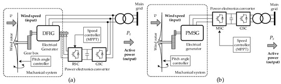
Figure 1.
General scheme of variable-speed wind turbines: (a) DFIG-WT, (b) SGFC-WT.
Figure 1 shows the main components of a DFIG-WT (Type III), and a SGFC-WT (Type IV). In both cases, the constructive similarity of these two models can be appreciated: a wind rotor; a back-to-back PEC composed of a rotor side converter (RSC), in the case of DFIG-WT, and machine side converter (MSC), in SGFC-WT, and a grid side converter (GSC); an electrical generator controlled by an RSC or MSC (under MPPT efficiency criteria); a pitch controller; and a GSC that governs the flow of active and reactive power injected into the grid at the point of common coupling (PCC).
These similarities allow us to propose a generic model of VSWT, which we have outlined in Figure 2. An attempt has been made to maintain a modular structure, such that it allows the addition and/or improvement of some components, in addition to making it possible to implement additional control strategies without this implying greater difficulties and conflicts between the variables involved [7,16]. In the diagram, Tt and Tem are the mechanical and the electromagnetic torque, respectively. Pg is the total output active power, t and g are the angular speed of the turbine and the electric generator, and v and β denote the wind speed and the blade pitch angle. At this point, it is important to mention that the short-term operation of the blocks: wind rotor, pitch angle controller, mechanical system, and active power controller (by MPPT) were successfully validated by simulation in [8]. This modular design incorporates two new and essential components: an approximate representation of the power electronic converter and the generator, and a pair of closed-loop controllers that regulate the active and reactive power injected into the grid.
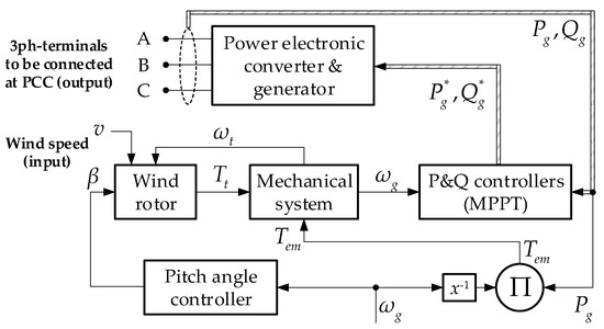
Figure 2.
Schematic representation of the proposed extended simplified electromechanical model of the VSWT.
Figure 3 shows the block diagram of the simplified electromechanical model of a VSWT, which takes part of the simplified WT model proposed by the authors in [8] and the simplified PEC model presented by the authors in [18]. Both are carefully articulated to achieve adequate performance and in adherence to the theoretical foundations of each of them.
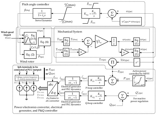
Figure 3.
Scheme representation of the main components of the proposed VSWT model.
The following lines present the formulation and a description of each of the components that make up the proposed model.
The set of Equation (1) shows the conversion of the input and output variables of the mechanical system block to per unit (p.u.) magnitudes.
where: , , and represent torque, power, and angular speed; subscripts and represent the variables referring to the generator and the turbine, respectively; , , and are the grid frequency, the number of pole pairs of the electrical generator and the gearbox ratio, respectively.
Equations (2)–(6) represent the dynamics of the wind rotor [8]:
where: , , and represent rotor radius, air density, and power coefficient, respectively; is the tip speed ratio; and are the power and speed constants, respectively, depending on the constructive characteristics of the wind rotor; and – are constants for approximation of the power coefficient for three-blade wind turbines and that are related to their construction characteristics; these constants are described in detail in refs. [23,24].
The VSWT speed controller uses an MPPT algorithm to extract power optimally. In Figure 4, this characteristic is represented by Equation (7), where is the optimization constant, whose value depends on the type of turbine. Segment A–B in Figure 4 is the start zone of the WT. Then, the optimization zone modifies the rotor speed by adjusting the points of maximum power in segment B–C. During operation of segment C–D, the mechanical speed of the WT is approximately constant until reaching the nominal electrical power. Finally, if the rotor speed exceeds point D, the pitch angle controller is enabled.
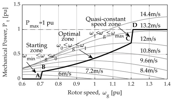
Figure 4.
MPPT algorithm implemented in the proposal.
The PEC subsystem in Figure 3 is implemented according to the simplified solution provided by the authors in [18]. The PEC has a three-phase representation modeled by means of a controlled current source. This source must inject three-phase currents , and whose amplitude and phase will be defined according to the control criteria implemented and the applications assigned to the converter. For the generation of the current command signals, the theory of the d−q coordinate system is applied, as explained below:
In order to control the active power, , a PI closed-loop controller is used, generating the output a signal , represented in Equation (8). This signal is applied to a first-order delay function, introduced to represent the controller time to reach the control variable, .
The reactive power control , is similar to the previously described scheme; in this case, the control variable is , Equation (9).
The generated signals ( and ), are transformed in real time by means of a phase closed loop (PLL); then, the reference signals are evaluated by the Park transform by means of Equation (10). Finally, to provide feedback to the PI controllers of each of the control loops, the instantaneous active and reactive powers injected by the controlled current sources are measured. The output signals are , and , in amperes, as shown in Figure 3. For further details, ref. [18] presents the detailed modeling of the PEC.
where: , , and are the direct axis, quadrature, and homopolar components, respectively; , , and are three-phase currents, and is the angular frequency of the grid voltage at PCC.
3. Results and Discussion
3.1. Validation of the Model
To validate the simplified VSWT and PEC model proposed in this work, this section analyzes the dynamics of the main mechanical and electrical variables step-by-step by comparing them with pre-designed models in MATLAB/Simulink®.
3.1.1. Validation of the Simplified Electro-Mechanical VSWT-Model
First, we validate the mechanical stage of the simplified model proposed. Then, the interaction of the different subsystems diagrammed in Figure 2 will be tested, except the “Power electronic converter & generator” block, which is replaced by a first-order transfer function with time constant τc, similar to the procedure reported in [8]. This adaptation is referred to as Figure 2* in the illustrations below. The simplified model is compared with a Wind Turbine Doubly-Fed Induction Generator block (Phasor Type) from MATLAB/Simulink® [25], considering a robust model that includes mechanical, electrical, and electromagnetic effects in detail. To have a comparative frame of reference, both models have been subjected to the same operating conditions and parameters. In this sense, the reference model has been connected, with its power losses disabled, to a bus with zero short-circuit impedance, following the diagram shown in Figure 5.
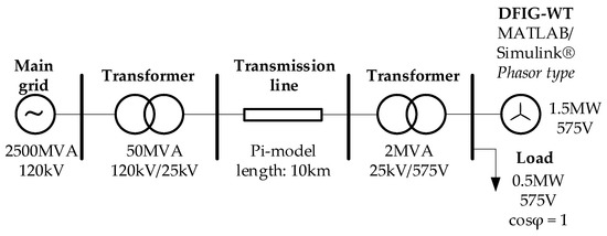
Figure 5.
Schematic representation of the reference-test bench designed for the assessment of the proposal (Detailed model).
The input variables for both models consist of an increasing stepped wind profile (minimum speed of 8 m/s and maximum of 14 m/s with an increasing rate of 2 m/s in steps of 20 s), and a profile decreasing from (14 m/s to 8 m/s) similarly. Figure 6 shows the behavior of the variables of interest , , and . The results show a minimum delay between both models, of about 3% of the WT inertia constant (see Table A1 in Appendix A). In general, the transient and steady-state response have accurate approximations.
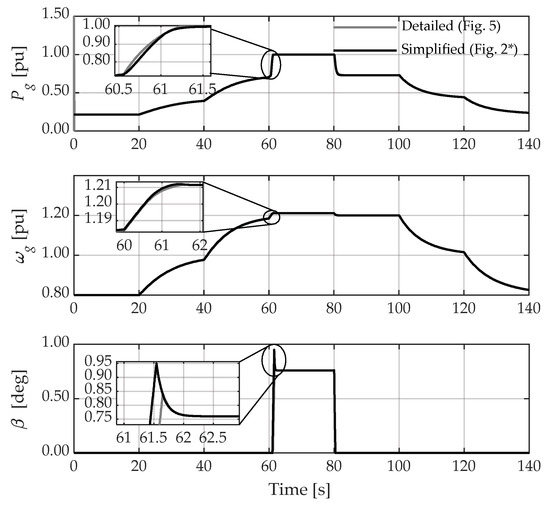
Figure 6.
Comparison of the mechanical stage of the simplified VSWT model vs. detailed MATLAB/Simulink model.
3.1.2. Validation of the Simplified Representation of the PEC
This section presents a comparative analysis of the performance of two PEC models, the proposed simplified model (Figure 7) and the detailed model taken as reference (Figure 8). The first of these is a proposal by the authors presented in [18], which has been included in the lower part of the scheme of Figure 3 to achieve the extension of the simplified VSWT model pursued in this work. In the diagram of Figure 7, the PI block contains a proportional-integral controller, and the FOTF block is a first-order transfer function representing the switching dynamics of the transistors, current inner loops, and delays in the measurement of variables, among others, until the id and iq setpoints are reached.
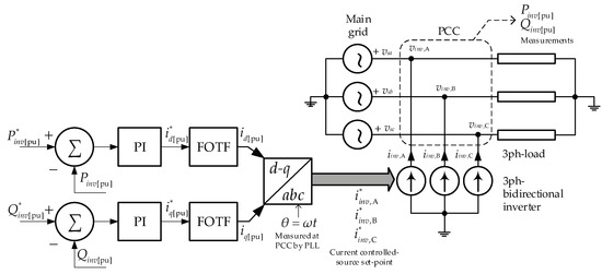
Figure 7.
Schematic representation of the simplified PEC model.
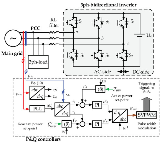
Figure 8.
Schematic representation of the detailed PEC model taken as reference.
To assess their time-domain behavior, the numerical results generated by the two models by simulation are compared with the real data records obtained from a 50 kW commercial PEC installed in a Microgrid Laboratory. For this purpose, the power setpoint signals shown in Figure 9 are applied to the models and they are subjected to the same operating conditions on the test bench designed in MATLAB/Simulink® and in the laboratory. Section 3.2 briefly describes the Microgrid Laboratory and provides further information on the actual PEC prototype used in this study.
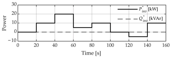
Figure 9.
Setpoint signals of power applied to the PEC models and the actual prototype.
Figure 10 shows the results obtained from the simulation and laboratory tests. It is shown that the amplitude and the temporal evolution of the active and reactive power graphs have a strong correlation (detailed, simplified, and real).
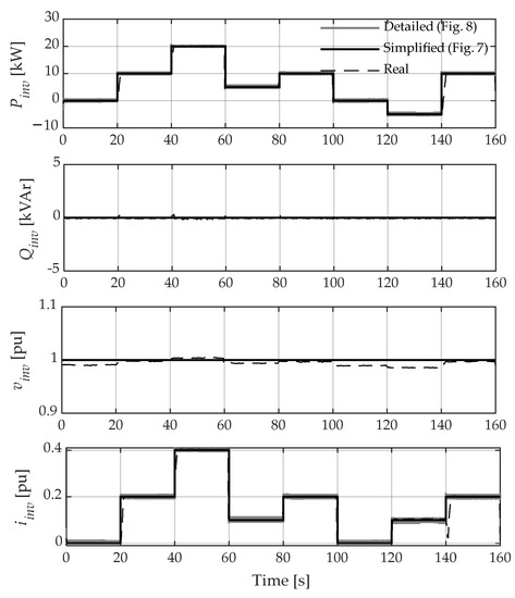
Figure 10.
Validation of the simplified PEC model (simulation and experimental).
It is obvious that the results are not perfect due to external factors, i.e., there is a small voltage fluctuation in the PCC because the real prototype is connected to the main utility grid, whose Thevenin impedance at that point is greater than that which has been considered in the simulation models (in the simulation, the Thevenin impedance of the grid at the PCC is negligible (infinite bus)).
3.1.3. Validation of the Extended Simplified VSWT Model in Simulation
This section presents the validation of the complete model proposed (WT and power electronic converter). Figure 11 shows the validation results of the proposed model (Figure 4) and the reference model (Figure 5). The results are similar with respect to Figure 6; the coincidence of responses from both models is encouraging. The Pg dynamics at the output of the proposed model is obtained from the voltage and current measured at the PCC (Figure 12), which is very similar to that achieved with the reference model. In this case, the computational effort in both models has been compared and the results show that the proposed model reduces the computation time by 80% with respect to the detailed model (Figure 5). This computational benefit is achieved despite the fact that the proposed model uses the “continuous” mode for its numerical solver in MATLAB, while the reference model uses the “phasor” approximation to reduce its computational load. Table 1 provides further details about the computational times achieved by running the two models for the simulated case study for a time horizon of 140 s.
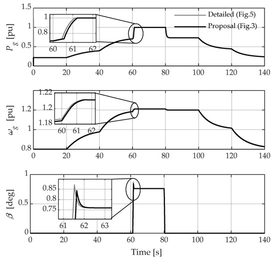
Figure 11.
Validation of the proposal in simulation: electrical and mechanical variables.
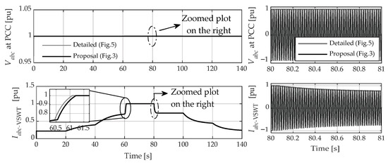
Figure 12.
Validation of the proposal in simulation: electrical variables measured at the PCC.

Table 1.
Detail of the computation times achieved with the reference and the proposed models.
Among other relevant results, Figure 12 shows the positive sequence components of the PCC voltage and the current sent to the grid by the VSWT. The results demonstrate a high correlation of these variables between the proposed and the detailed model. In this sense, the instantaneous three-phase voltage and current variables offered by the proposed model are observed in more detail (zoomed plot) for the same computational cost mentioned in the previous paragraph. This feature is relevant since having the dynamics of the instantaneous electrical variables allows expanding the spectrum of grid studies to analysis related to the behavior of the frequency of said signals (primary frequency control) and power quality studies, which is difficult to achieve with the reference model given its phasor approach for solving the dynamics of its internal components.
3.2. Comparison of the Expected and Emulated Model Results in the Laboratory
To determine the experimental validity of the proposed model, exhaustive tests have been done under real conditions in the Microgrid Laboratory of the Centro Científico, Tecnológico y de Investigación Balzay (CCTI-B) of the Universidad de Cuenca, Ecuador. This laboratory has various agents of energy generation, consumption, and storage. In addition, it has the possibility of working connected to the utility grid (grid-connected mode) or in island mode [26,27]. Figure 13 shows a schematic representation of the main components of the laboratory.
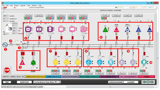
Figure 13.
Schematic representation of CCTI-B Microgrid Laboratory components: 1. Utility grid, 2. Bus operation in grid-connected mode, 3. Bus operation in isolated mode, 4. Energy storage components, 5. Loads and programmable sources, 6. Other loads, 7. Photovoltaic generation, 8. Mini-wind generation, 9. Thermal generation, 10. Hydrokinetic generation.
According to the scope of this paper, in the Microgrid Laboratory, the energy storage system in Lithium-Ion (Li-ion) batteries is selected for the emulation of power injection from a VSWT to the utility grid. The active and reactive power setpoint signals will be generated by the proposed model, implemented and executed in MATLAB/Simulink, and then applied to the SCADA system of the microgrid to control, in real time, the setpoint signals that the PEC must reach. The general scheme of the test subsystem is shown in Figure 14 and the parameters of the PEC are shown in Table A2 in Appendix B.
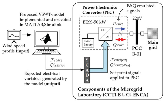
Figure 14.
General scheme proposed for emulating the dynamics of some electrical variables of the VSWT model expected and emulated in a Microgrid-Laboratory.
The expected and emulated in the laboratory results have been subjected to the same setpoint signals shown in Figure 9. The results, shown in Figure 15, demonstrate the feasibility and accuracy of the proposed model, as the insignificant deviations caused by the time constants of the experiments do not compromise the behavior of the model. This result is important since it allows establishing a starting point for further studies of a VSWT in terms of P and Q where greater computational efforts will be required, which will be more efficient using the simplified model proposed in this paper.
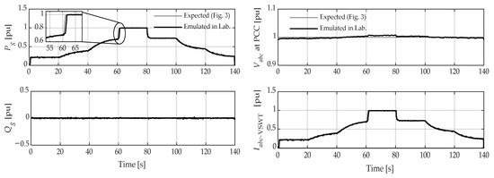
Figure 15.
Comparison of the dynamics of some electrical variables of the expected model with respect to emulated in laboratory.
4. Conclusions
This paper presents a simplified model for a variable-speed wind turbine by introducing an approximate representation of the power electronic converter. The objective of this model is to reduce the computational effort and to allow one to analyze the dynamics of instantaneous electrical variables, enabling the extension of the scope of network studies related to the behavior of the grid frequency (primary frequency control) and power quality studies in high-penetrated wind power systems. All of these are at a lower cost and computational time. Validation of the proposed simplified model is compared with a Wind Turbine Doubly-Fed Induction Generator block (Phasor Type) from MATLAB/Simulink® and with laboratory experiments under controlled conditions. The main novelty of this paper is the development of a simplified electromechanical model of a variable speed wind turbine considering an electronic power controller that optimizes the computational effort, with the aim of having a computer tool that allows the performance of dynamic analyses that would be intractable when simulating frequency events in large-scale power systems with complete models.
The results show a minimal delay between the proposed model and the DFIG-WT MATLAB/Simulink®, representing approximately 3% of the WT inertia constant. In general, the transient and steady-state response have accurate approximations.
Regarding the proposed model of the PEC that constitutes the extended VSWT, it is obvious that the results are not perfect due to external factors, i.e., there is a small voltage fluctuation in the PCC due to the actual prototype being connected to the mains, whose Thevenin impedance at that point is greater than that considered in the simulation models. Even so, the experimental results show that the electrical variables obtained in practice are similar to the reference models implemented in simulation within the time frame analyzed.
The computational effort in both models has been compared; the results show that the proposed model reduces the computational time by 80% with respect to the detailed model. This computational benefit is achieved even though the proposed model uses the “continuous” mode for its numerical solver in MATLAB, while the reference model uses the “phasor” approximation to reduce its computational burden.
The results show a high correlation of these variables between the fluctuations of the proposed and the detailed model.
Finally, the reduction of the simulation time achieved with the proposal also makes possible the emulation in real time of certain electrical variables of the VSWT in the laboratory, as has been demonstrated in this work. Furthermore, having a real test bench to assess the integration of wind generation in a utility grid or its interaction with other agents into an islanded microgrid constitutes a valuable means of verifying the effectiveness of different techniques aimed at improving the dynamic characteristics of such systems.
Author Contributions
Conceptualization, D.O. and S.M.; Data curation, D.O.; Formal analysis, P.A., D.O. and S.M.; Funding acquisition, S.M.; Investigation, P.A.; Methodology, P.A.; Project administration, D.O.; Resources, D.O.; Software, D.O.; Supervision, D.O. and S.M.; Validation, D.O.; Visualization, S.M.; Writing—original draft, P.A.; Writing—review & editing, P.A., D.O. and S.M. All authors have read and agreed to the published version of the manuscript.
Funding
Part of the work documented in this manuscript is part of the activities carried out in the project entitled: “Movilidad Eléctrica: retos, limitaciones y plan de implementación en el régimen especial de la Provincia de Galápagos enfocada en el desarrollo sostenible y su factibilidad en la Ciudad de Cuenca”, II Concurso de Proyectos de Investigación—Vinculación, Vicerrectorado de Investigación y la Dirección de Vinculación con la Sociedad de la Universidad de Cuenca. This project is currently co-directed by the author Danny Ochoa. Part of the research described in this work was funded by the Spanish national research agency Agencia Estatal de Investigación, grant number PID2019-108966RB-I00/AEI/10.13039/501100011033.
Data Availability Statement
Not applicable.
Acknowledgments
The author Paul Arévalo thanks the Call for Grants for the Requalification of the Spanish University System for 2021–2023, and the Margarita Salas Grants for the training of young doctors awarded by the Ministry of Universities and financed by the European Union—Next Generation EU. Finally, the authors thank Universidad de Cuenca for easing access to the facilities of the Microgrid Laboratory of the Centro Científico Tecnológico y de Investigación Balzay (CCTI-B), for allowing the use of its equipment, and for authorizing members of its staff (Edisson Villa and Vinicio Iñiguez) the provision of technical support necessary to carry out the experiments described in this article.
Conflicts of Interest
The authors declare no conflict of interest.
Appendix A
- A.
- DFIG-WT parameters
Table A1.
DFIG-Based Wind Turbine Parameters.
Table A1.
DFIG-Based Wind Turbine Parameters.
| Parameter | Symbol | Value and Units |
|---|---|---|
| Base power | 1.5 MW | |
| Max./Min. power of the generator | 1/0.04 pu | |
| Max./Min. torque of the generator | 0.826/0.057 pu | |
| Wind speed at | 12 m/s | |
| Number of pole pairs | 2 | |
| Nominal frequency | 60 Hz | |
| Base speed of the turbine | 1.644 rad/s | |
| Base speed of the generator | 157.08 rad/s | |
| Air density | 1.225 kg/m3 | |
| Radius of the rotor | 38.5 m | |
| Power constant | ||
| Speed constant | 63.29 m/s | |
| Min./Max. blade pitch angle | 0°/45° | |
| Maximum blade pitch angle rate | 2°/s | |
| Turbine-generator inertia constant | 5.29 s | |
| DFIG-PEC time constant | 20 ms | |
| Blade pitch servo time constant | 0 s | |
| Pitch controller gains | 500/0 | |
| Speed controller gains | 0.3/8 |
- B.
- MPPT-curve parameters
Appendix B
Table A2.
PEC parameters.
Table A2.
PEC parameters.
| Utility Grid Parameters | Symbol | Value and Units |
|---|---|---|
| Three-phase source | 480 V | |
| f | 60 Hz | |
| Three-phase load | 1 kW | |
| Detailed model parameters | Symbol | Value and Units |
| Modulation SVPWM | 20 kHz | |
| PI controller | 50, 2500 | |
| RL filter series | 0.1 Ω | |
| 12.7 mH | ||
| DC voltage | 800 V | |
| Simplified model parameters | Symbol | Value and Units |
| Active power PI controller | 5, 50 | |
| Reactive power PI controller | −5, −50 | |
| Time constant (delay function) | 0.02 s |
References
- Worku, M.Y. Recent Advances in Energy Storage Systems for Renewable Source Grid Integration: A Comprehensive Review. Sustainability 2022, 14, 5985. [Google Scholar] [CrossRef]
- Tchakoua, P.; Wamkeue, R.; Ouhrouche, M.; Slaoui-Hasnaoui, F.; Tameghe, T.A.; Ekemb, G. Wind Turbine Condition Monitoring: State-of-the-Art Review, New Trends, and Future Challenges. Energies 2014, 7, 2595–2630. [Google Scholar] [CrossRef]
- Herbert-Acero, J.F.; Probst, O.; Réthoré, P.E.; Larsen, G.C.; Castillo-Villar, K.K. A Review of Methodological Approaches for the Design and Optimization of Wind Farms. Energies 2014, 7, 6930–7016. [Google Scholar] [CrossRef]
- Jaen-Cuellar, A.Y.; Elvira-Ortiz, D.A.; Osornio-Rios, R.A.; Antonino-Daviu, J.A. Advances in Fault Condition Monitoring for Solar Photovoltaic and Wind Turbine Energy Generation: A Review. Energies 2022, 15, 5404. [Google Scholar] [CrossRef]
- Aljafari, B.; Stephenraj, J.P.; Vairavasundaram, I.; Rassiah, R.S. Steady State Modeling and Performance Analysis of a Wind Turbine-Based Doubly Fed Induction Generator System with Rotor Control. Energies 2022, 15, 3327. [Google Scholar] [CrossRef]
- Haces-Fernandez, F.; Cruz-Mendoza, M.; Li, H. Onshore Wind Farm Development: Technologies and Layouts. Energies 2022, 15, 2381. [Google Scholar] [CrossRef]
- Ochoa, D.; Martinez, S. A simplified electro-mechanical model of a DFIG-based wind turbine for primary frequency control studies. IEEE Lat. Am. Trans. 2016, 14, 3614–3620. [Google Scholar] [CrossRef]
- Ochoa, D.; Martinez, S. Fast-Frequency Response Provided by DFIG-Wind Turbines and its Impact on the Grid. IEEE Trans. Power Syst. 2017, 32, 4002–4011. [Google Scholar] [CrossRef]
- Kayikçi, M.; Milanović, J.V. Dynamic contribution of DFIG-based wind plants to system frequency disturbances. IEEE Trans. Power Syst. 2009, 24, 859–867. [Google Scholar] [CrossRef]
- Ihedrane, Y.; Bekkali, C.E.; Bossoufi, B.; Bouderbala, M. Control of Power of a DFIG Generator with MPPT Technique for Wind Turbines Variable Speed. In Modeling, Identification and Control Methods in Renewable Energy Systems. Green Energy and Technology; Derbel, N., Zhu, Q., Eds.; Springer: Singapore, 2018; pp. 105–129. [Google Scholar]
- Jenkal, H.; Lamnadi, M.; Mensou, S.; Bossoufi, B.; Boulezhar, A. A robust control for a variable wind speed conversion system energy based on a DFIG using Backstepping. Wind Eng. 2022, 19, 0309524X221122512. [Google Scholar] [CrossRef]
- Gianto, R. Constant voltage model of DFIG-based variable speed wind turbine for load flow analysis. Energies 2021, 14, 8549. [Google Scholar] [CrossRef]
- Seshadri Sravan Kumar, V.; Thukaram, D. Accurate modeling of doubly fed induction generator based wind farms in load flow analysis. Electr. Power Syst. Res. 2018, 155, 363–371. [Google Scholar]
- Prasad, R.M.; Mulla, M.A. Mathematical Modeling and Position-Sensorless Algorithm for Stator-Side Field-Oriented Control of Rotor-Tied DFIG in Rotor Flux Reference Frame. IEEE Trans. Energy Convers. 2020, 35, 631–639. [Google Scholar] [CrossRef]
- Behabtu, H.A.; Coosemans, T.; Berecibar, M.; Fante, K.A.; Kebede, A.A.; van Mierlo, J.; Messagie, M. Performance evaluation of grid-connected wind turbine generators. Energies 2021, 14, 6807. [Google Scholar] [CrossRef]
- Ochoa, D.; Martinez, S. Frequency dependent strategy for mitigating wind power fluctuations of a doubly-fed induction generator wind turbine based on virtual inertia control and blade pitch angle regulation. Renew. Energy 2018, 128, 108–124. [Google Scholar] [CrossRef]
- Ochoa, D.; Martinez, S. Proposals for Enhancing Frequency Control in Weak and Isolated Power Systems: Application to the Wind-Diesel Power System of San Cristobal Island-Ecuador. Energies 2018, 11, 910. [Google Scholar] [CrossRef]
- Ochoa, D. Modelo simplificado de una interfaz de conexión a la red basada en un convertidor electrónico de potencia para estudios de red en régimen dinámico. Ingenius 2021, 26, 87–98. [Google Scholar] [CrossRef]
- Siami, M.; Khaburi, D.A.; Rivera, M.; Rodríguez, J. A Computationally Efficient Lookup Table Based FCS-MPC for PMSM Drives Fed by Matrix Converters. IEEE Trans. Ind. Electron. 2017, 64, 7645–7654. [Google Scholar] [CrossRef]
- Siami, M.; Khaburi, D.A.; Rodriguez, J. Simplified Finite Control Set-Model Predictive Control for Matrix Converter-Fed PMSM Drives. IEEE Trans. Power Electron. 2018, 33, 2438–2446. [Google Scholar] [CrossRef]
- Lei, J.; Feng, S.; Wheeler, P.; Zhou, B.; Zhao, J. Steady-State Error Suppression and Simplified Implementation of Direct Source Current Control for Matrix Converter with Model Predictive Control. IEEE Trans. Power Electron. 2020, 35, 3183–3194. [Google Scholar] [CrossRef]
- Bhesaniya, M.M.; Shukla, A. Computationally efficient method for simulating current source modular multilevel converter. In Proceedings of the 18th European Conference on Power Electronics and Applications (EPE’16 ECCE Europe), Karlsruhe, Germany, 5–9 September 2016. [Google Scholar]
- Schmidlin Junior, C.R.; Araujo Lima, F.K. Wind Turbine and PMSG Dynamic Modelling in PSIM. IEEE Lat. Am. Trans. 2016, 14, 4115–4120. [Google Scholar] [CrossRef]
- Reyes, V.; Rodriguez, J.J.; Carranza, O.; Ortega, R. Review of mathematical models of both the power coefficient and the torque coefficient in wind turbines. In Proceedings of the IEEE 24th International Symposium on Industrial Electronics (ISIE), Buzios, Brazil, 3–5 June 2015. [Google Scholar]
- MathWorks—Makers of MATLAB and Simulink—MATLAB & Simulink, (n.d.). Available online: https://www.mathworks.com/ (accessed on 14 October 2022).
- Espinoza, J.L.; Gonzalez, L.G.; Sempertegui, R. Micro grid laboratory as a tool for research on non-conventional energy sources in Ecuador. In Proceedings of the 2017 IEEE International Autumn Meeting on Power, Electronics and Computing (ROPEC), Ixtapa, Mexico, 8–10 November 2017. [Google Scholar]
- Rey, J.M.; Vera, G.A.; Acevedo-Rueda, P.; Solano, J.; Mantilla, M.A.; Llanos, J.; Saez, D. A Review of Microgrids in Latin America: Laboratories and Test Systems. IEEE Lat. Am. Trans. 2022, 20, 1000–1011. [Google Scholar] [CrossRef]
Publisher’s Note: MDPI stays neutral with regard to jurisdictional claims in published maps and institutional affiliations. |
© 2022 by the authors. Licensee MDPI, Basel, Switzerland. This article is an open access article distributed under the terms and conditions of the Creative Commons Attribution (CC BY) license (https://creativecommons.org/licenses/by/4.0/).