Article

Simulation of Active Echo Cancellation Effects Using the ARCS Concept

1
School of Electronic and Information Engineering, Beihang University, Beijing 100191, China
2
Beijing Key Laboratory of Microwave Sensing and Security Applications, Beihang University, Beijing 100191, China
3
Shenzhen Institute of Beihang University, Shenzhen 518000, China
4
Electrical and Automation Engineering, Nanjing Normal University, Nanjing 210023, China
5
No. 8511 Research Institute of CASIC, Nanjing 210007, China
*
Author to whom correspondence should be addressed.
Electronics 2022, 11(23), 3891; https://doi.org/10.3390/electronics11233891
Submission received: 31 October 2022 / Revised: 19 November 2022 / Accepted: 23 November 2022 / Published: 24 November 2022
(This article belongs to the Special Issue Advances in Electromagnetic Interference and Protection)

Abstract

:
Active echo cancellation is an efficient method for reducing the target detected probability. The radar cross section (RCS) of the target detected by radar after using the active echo cancellation method is defined as the active radar cross section (ARCS). The ARCS concept, which may be used to evaluate reflection of the target under the effect of multiple antennas, is employed to design and achieve echo cancellation. In this paper, numerical simulation for active echo cancellation using antennas is designed. The direction of the radiation source is obtained by means of dual antenna angle measurement. Active echo cancellation is implemented by adjusting the radiation power and phase of the echo cancellation antenna. By using the proposed dual antenna structure, ARCS in the direction of the object facing the radiation source and its vicinity is significantly reduced. In addition, the effect of antenna position on reflection cancellation is discussed. From these simulation results, we conclude that the proposed method is efficient in reducing the target scattering intensity. Such investigation can be extensively applied into designing active echo cancellation strategies.

1. Introduction

With the rapid development of radar technology and electronic industry, the electromagnetic environment has become increasingly complex [1,2]. The investigation of electromagnetic scattering in complex environments shows its potential in military and civilian employment [3,4]. Among them, target detection and electromagnetic stealth can be regarded as important scientific areas of current research [5,6].
In a complex electromagnetic environment, it can be noticed that it is impossible for targets to be irradiated merely by a single radar source [7]. Thus, influence on other external electronic equipment and active equipment must be considered during the investigation. Owing to the introducing of an active radar cross section (ARCS), the scattering characteristics in the circumstances of multiple radiation sources can be expressed and characterized [8]. ARCS is introduced according to the equivalent method. Hence, a scattering field generated by an interference source can be superimposed into the total field. Then, in order to further investigate the characteristic on the external radiator, the influences on the frequency, field amplitude, phase and polarization of multiple radiators are considered, which can significantly affect the target characteristics [9]. Until now, the investigation of ARCS focuses merely on the concept and on multiple radiators [8,9].
Over time, target stealth in a complex electromagnetic environment has become much more important [10,11]. The mainstream methods of current stealth are absorbing material covering and shape changing [12,13]. It is becoming difficult to persist in these stealth methods due to the bottleneck on materials development and limitations on targets themselves. Active echo cancellation is one of the most efficient ways which uses a signal to interfere with each other in space [14]. Such an operation allows the stealth for radar without changing the material and shape. In previous work on echo cancellation, they mainly focus on the acoustic signals [15], jamming signals [16], and clutter signals [17]. Recently, active echo cancellation has been widely used in radar detection. The active echo cancellation of synthetic aperture radar has been studied [18]. Reference [19] studied the effect of different antennas on dual station characteristics. To the best of our knowledge, no one has investigated the usage of active echo cancellation direction directly to reduce the radar echo signals in terms of RCS reduction. Meanwhile, ARCS shows its potential in quantifying the electromagnetic scattering in active echo cancellation.
Here, the ARCS concept is employed in the evaluation of active echo cancellation effects. Meanwhile, the simulation procedures of active echo cancellation are proposed. The effectiveness is testified through the simulation with an antenna on the surface of aircraft. A dual-antenna structure is proposed to achieve active echo cancellation. Compared with existing methods using absorbing materials coated on the surface of the target, the proposed method is simple in structure, easy to implement, and has lower cost and a better cancellation effect. From the aspect of active echo cancellation of scattering field and influences of antenna parameters and surface current on the active echo cancellation effect, the results show that the proposed method is efficient in reducing the target scattering intensity and analyzing active echo cancellation.

2. Methods

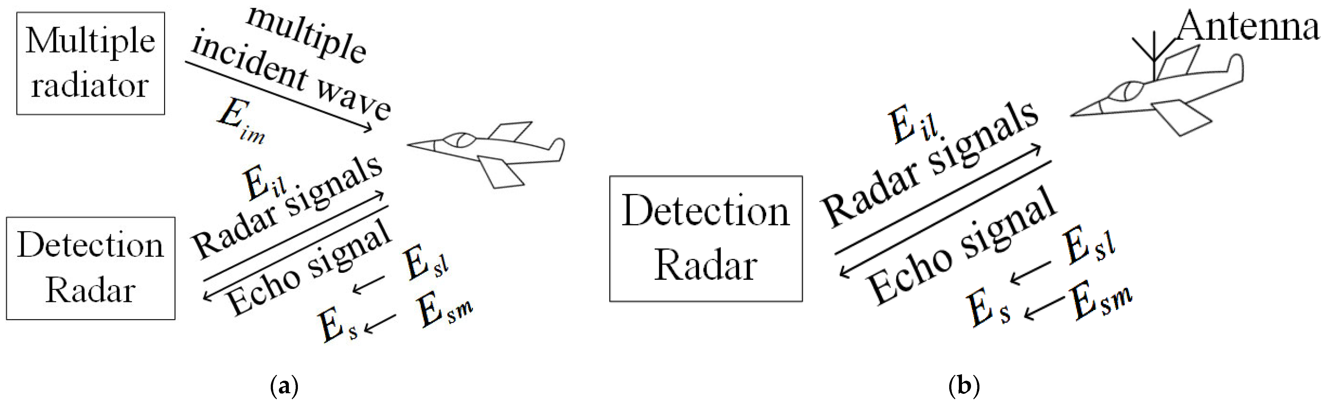
2.1. Active Echo Cancellation Theory Based on ARCS Concept

When the targets are illuminated by a radar wave, field energy is scattered along all directions. The distribution of energy in space can be represented by the radar cross section (RCS). RCS is a physical quantity that measures the ability of targets to scatter radar waves. The equations of conventional RCS can be obtained as:
σ 1 = lim R 4 π R 2 E s l 2 E i l 2 ,
where E s l is the scattered field at radar antenna from targets, E i l is the target incident field and R represents the distance from targets to the radar antenna. The conventional definition of RCS characterizes the scattered intensity of a target after it has been irradiated by radar waves. It should be noted that such a concept is only efficient in single radar radiation.
When the conductor is irradiated by multiple incident waves or equipped with active equipment, the surface current of the conductor changes dramatically [20]. This change leads to the variation of electromagnetic scattering characteristics of the conductor. In this case, the traditional definition is no longer applicable. As shown in Figure 1a, the target is illuminated by radar signals and multiple incident waves. It can be observed from Figure 1b that the target is radiated by radar signals and the antenna. The echo signals are generated by the combined effect of radar, multiple radiators and antennas. In this circumstance, the field energy distribution can be named as ARCS.
The definition of ARCS can be written as
σ m 2 = lim R 4 π R 2 E s 2 E s l 2 ,
where E s is the total scattering field which can be received by radar system antennas and it can be expressed as
E s = E s l + E s m ,
where E s m is the scattering field caused by multiple radiators and antennas. The radar receiving antenna is affected by their joint action with the scattered echoes from the target.
From the above discussion, it can be seen that there is a significant difference in the scattering field between ARCS and RCS. RCS represents the scattering field generated by the radar system, while ARCS characterizes the scattering field generated by the radar system, active equipment and multiple radiators. The influencing factors of ARCS include not only the physical parameters of the target and the parameters of the radar, but also the parameters of multiple incident waves and active equipment.
One of the most important features between field and wave is the coherent interaction between them. The interference effects may occur in scattered fields caused by radars, multiple radiators and antennas. It will consequently lead to the increase or cancellation of the electric field. Supposing the phases of E s l and E s m are φ 1 and φ 2 respectively, the ARCS can be written as
σ = lim R 4 π R 2 E s l e j φ 1 2 + E s m e j φ 2 2 + 2 E s l e j φ 1 E s m e j φ 2 E i l 2 ,
Supposing σ 2 is the RCS caused by cancellation signals. Therefore, σ can be given as
σ = σ 1 1 + σ 2 σ 1 + 2 σ 2 σ 1 cos φ 2 φ 1 ,
By analyzing (5), it can be known that the value of σ 2 can be significantly reduced by adjusting the phase. Similar to monostatic RCS, the observation point with the same radar position can be called monostatic ARCS. When the observation point is different from the radar position, it can be regarded as bistatic ARCS. The ARCS concept can be used to achieve the cancellation of electromagnetic wave signals in certain directions and has the potential to be applied to target stealth.

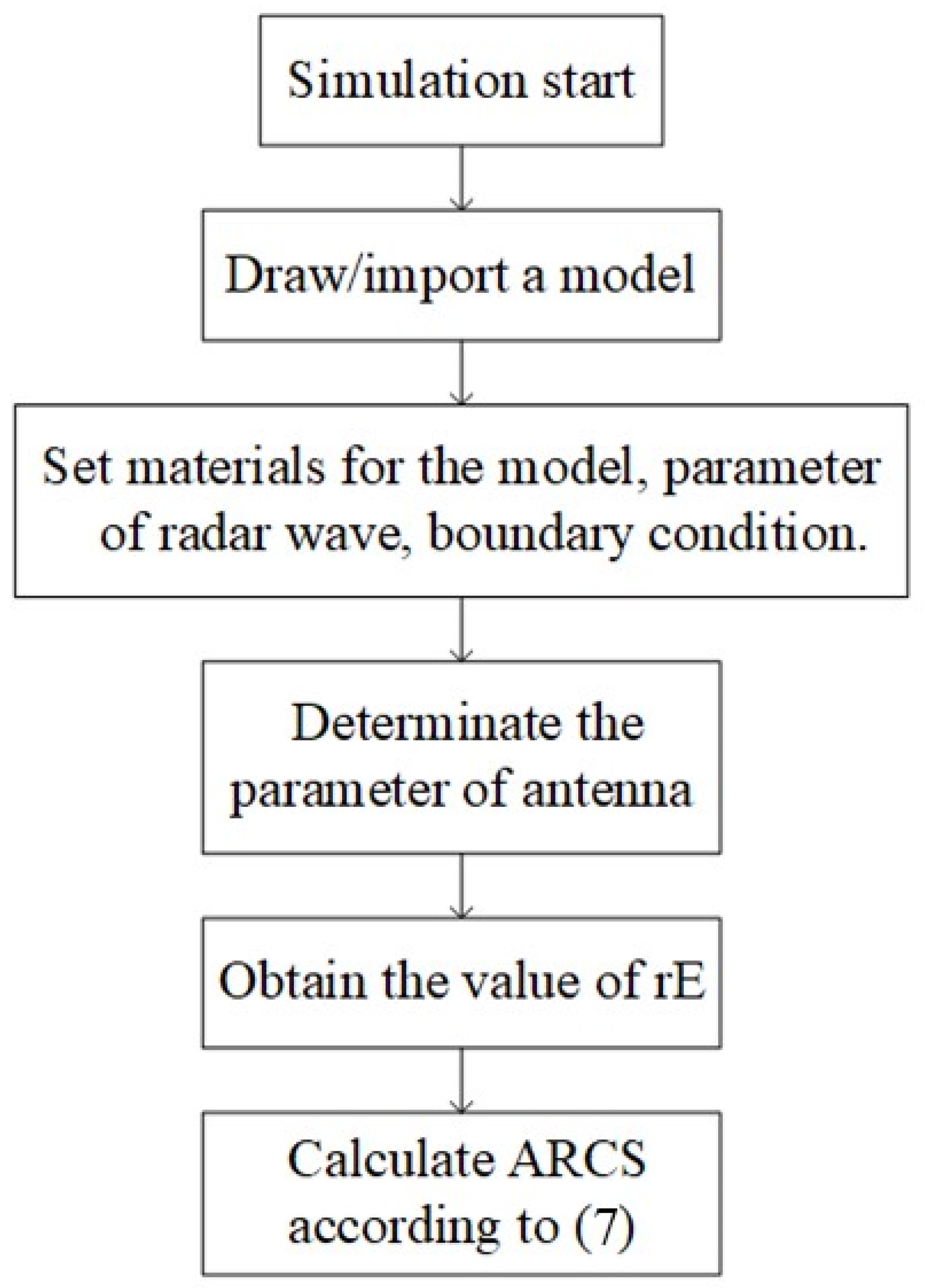
2.2. Active Echo Cancellation Evaluation Simulation Procedure
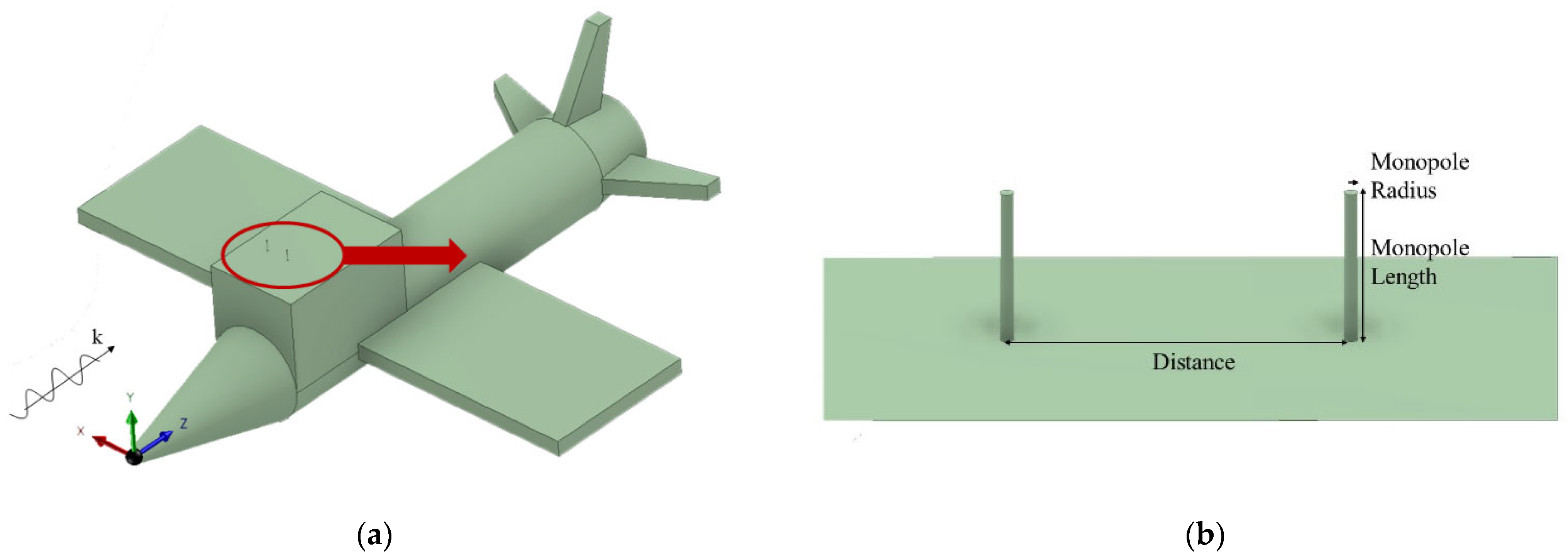
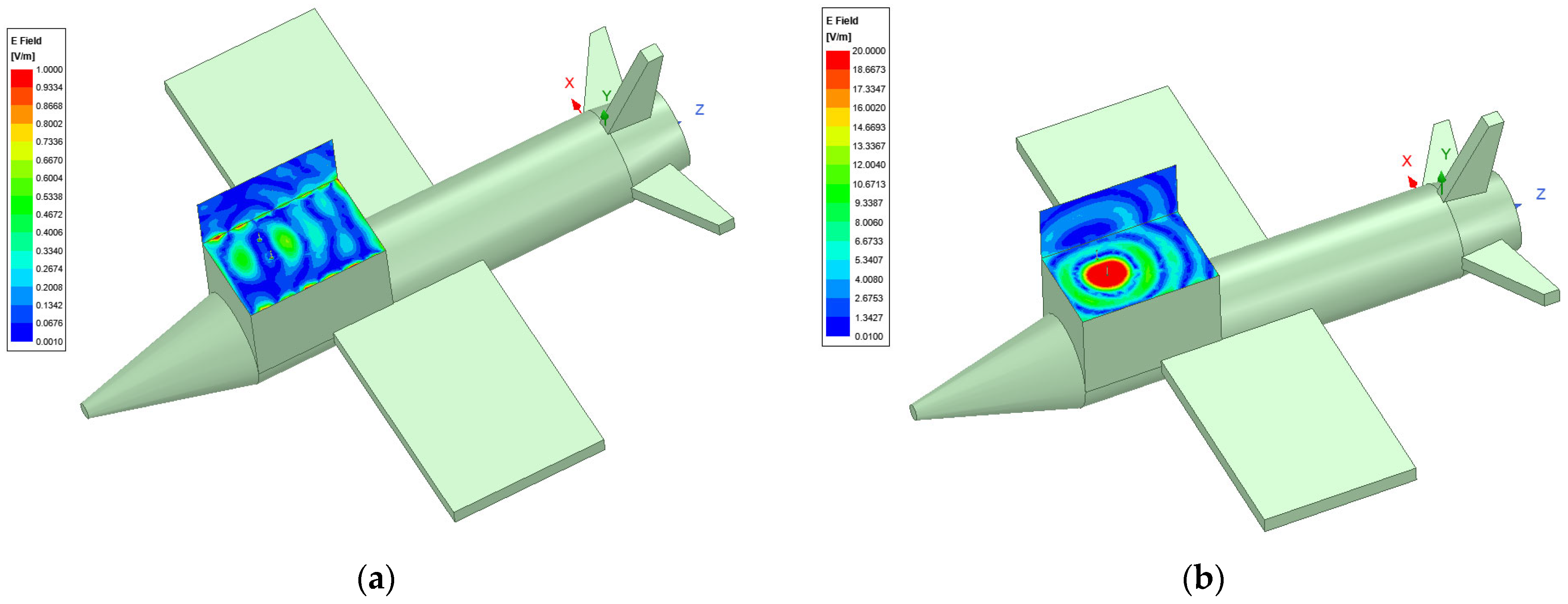
The combined effect of radiated fields and radar waves from active devices on the target results in a diversity of scattered fields. To achieve the stealth of the target, the active echo cancellation simulation procedure of the target is designed and analyzed by ARCS theory. The effect of antenna parameters on the electromagnetic scattering characteristics can also be expressed by ARCS. All simulations are calculated by HFSS.
As shown in (2), the process of calculating ARCS requires the value of the total scattered field in space. In HFSS, the value of r E which represents the parameter of far field can be calculated, where r is the distance from target to radar and E is the total electric field at a distance of r from radar. The total scattering field which can be received by radar system antennas can then be obtained as
E s = r E R ,
Then the ARCS can be written as
σ dB = 4 π log 10 r E 2 E i l 2 ,
The simulation procedure of evaluating active echo cancellation by ARCS concept through HFSS can be divided in five steps, as shown in Figure 2.
Simulations were designed to validate the active echo cancellation using the ARCS concept. We built a model of an aircraft with a dual antenna structure and added plane wave excitation to the aircraft in the head-on direction. The active echo cancellation is achieved by using the antenna to transmit an electromagnetic wave signal and adjusting the amplitude and phase of the signal emitted by the antenna. We then calculate its monostatic ARCS by HFSS simulation. More details are presented in Section 3.

3. Simulations

According to the theory mentioned in the previous section, when the radar signal is irradiated to the target, the active equipment on the target surface emits waves of the same frequency in the direction of the radar signal. By adjusting the amplitude and phase of the electromagnetic waves emitted by the active equipment, the echo signal received by the radar antenna is effectively reduced. To further investigate the active echo cancellation theory, numerical simulations are presented. An aircraft model with two antennas is used in the simulation. One of the antennas plays a dominant role to receive the signal and transmit electromagnetic waves for active echo cancellation, and the other antenna plays a secondary role to receive the signal together with the former to obtain the direction of the incident wave, as shown in Figure 3. The mark k indicates the direction of the incident electromagnetic wave. The electromagnetic field around the antenna system located on the aircraft model before and after the echo cancellation is shown in Figure 4.
The boundary dimension of the aircraft is 4.5 × 3.6 m in the horizontal plane. The material of the aircraft is a perfect electronic conductor. This antenna system consists of two monopole antennas. The operating frequency of the monopole antenna is 1 GHz. The monopole length is 69 mm and the monopole radius is 3 mm. The distance between two monopole antennas is 150 mm. The amplitude and phase characteristics of the signals emitted by the echo cancellation antenna are adjusted to decrease the scattered field of aircraft during the simulation.
The dimensions of the monopole antenna are obtained by HFSS software simulation. Its length is set to 1/4 wavelength according to its operating frequency, and then optimized according to the simulation results. When the antenna is placed on the aircraft, its reflection coefficient obtained by simulation is less than −10 dB.
In the proposed method, the scattered waves of the target in a specific direction are recorded in advance. Once the direction, amplitude and phase of the radar signal irradiated to the target are available, the amplitude and phase of the signal that should be emitted by the antenna for active echo cancellation can be obtained. The antenna on the target quickly emits canceling electromagnetic waves to reduce the ARCS, thus reducing the probability of being detected. The scattered electromagnetic fields of the target are obtained by numerical simulation in HFSS software. In a real scenario, the amplitude of the signals can be adjusted by the input power of the signal source, and the phase of the signals can be adjusted by the phasers, and the scattered electromagnetic fields of the target can be obtained by means of antenna measurement, such as the compact antenna test range.
The dual antenna structure is designed to receive the radar signal and obtain its amplitude and phase. In addition, by comparing the phase difference between the signals received by the two antennas, the direction of the radar can be calculated.
The head-on direction of the aircraft is chosen as the incident direction of the radar signal in the simulations, and the effect of phase change on the echo cancellation is studied first. The simulations were conducted in four cases with transmitting antenna feed power of 0.001 W, 0.01 W, 0.1 W and 0 W respectively, while the feed power of the auxiliary antenna is set to 0 W. The phase of the transmitting antenna was set to variable, ranging from 0° to 360° with an interval of 5°. By calculating the phase characteristics of the electromagnetic field, the active echo cancellation results are obtained for these four incidence cases with different power and phase characteristics. The simulation results are shown in Figure 5.
From the simulation results, we can find the existence of such a determined amplitude and phase of the electromagnetic wave emitted by the echo cancellation antenna, thus minimizing the ARCS of the target in a particular direction and a fixed frequency. The smaller the difference between the amplitude and phase of the emitted signal and this amplitude and phase, the better the effect of echo cancellation, which is consistent with the theory mentioned in Section 2.
The effect of antenna position on the echo cancellation effect is then discussed. The two antennas are placed symmetrically on both sides of the target, and the amplitude and phase of the transmitted signals from the echo cancellation antenna are adjusted to find the state that minimizes its ARCS. The echo cancellation antenna is then placed in the center of the target, and the other antenna is placed on one side, as in Figure 6, and we find the state with the minimum ARCS as well. The variation of the ARCS of the target with the phase of the echo cancellation signal in the two cases is shown in Figure 7.
As can be seen in Figure 7, when the two antennas are placed symmetrically on both sides of the target, the minimum ARCS of the target is −3.67 dB, while the minimum ARCS of the other structure of the target is −9.92 dB, which is much smaller than the former. We can consider the target as a whole and it can be regarded as a signal source emitting radar scattered waves. The scattering center of the target is considered to be the location of this signal source. Furthermore, the electromagnetic waves emitted by the echo cancellation antenna are used to reduce this signal. The closer these two sources are to each other, the better the signal reduction effect will be, so the location of the echo cancellation antenna should be as close as possible to the scattering center of the target.
The following simulation experiments are conducted for the ARCS in the direction adjacent to the aircraft head-on direction, and the direction is chosen to be within −10 to 10 degrees azimuth degrees of the horizontal plane. The minimum value of the target ARCS is found by adjusting the amplitude and phase of the emitted electromagnetic wave from the transmitting antenna, and the results are shown in Figure 8.
As can be seen in Figure 8, the ARCS of the target is effectively reduced in all the given directions. The ARCS is reduced by more than 6 dB in each of these directions, with a maximum reduction of 24.36 dB in the head-on direction. As long as the amplitude, phase of the incident wave and incident wave direction of the radar antenna are clarified by the dual-antenna receiving structure, the amplitude and phase of the electromagnetic wave that the target needs to transmit to reduce the ARCS can be obtained, the ARCS reduction can be achieved quickly and accurately according to the situation.
To further validate the proposed method, an aircraft of a different shape was selected for simulation. The boundary dimension of the aircraft is 5.5 × 5.7 m in the horizontal plane. The dual antenna structure was placed on the aircraft as shown in Figure 9. When the antenna has no input power, the monostatic ARCS of the aircraft is −6.6 dB. By adjusting the radiated power and phase of the echo cancellation antenna, the monostatic ARCS of the aircraft can be reduced to −24.6 dB, which is much smaller than the case without excitation. The effectiveness of the proposed method is demonstrated in this way. Experimental validation of active echo cancellation using the ARCS concept was carried out in a previous paper by our group [8].

4. Conclusions

In this paper, the ARCS concept is used to evaluate the active echo cancellation effect of an antenna. A dual antenna structure is proposed to determine the direction, amplitude and phase of radar signals and to apply active echo cancellation. The use of dual antenna reception allows the incoming wave direction of the radar to be sensed. The ARCS of the target is reduced by transmitting electromagnetic waves of suitable amplitude and phase based on the pre-stored information. According to the simulation results, the proposed method can reduce the monostatic ARCS of the target in a chosen direction and within 10 degrees of its vicinity by more than 6 dB. The proposed method can reduce the probability of the target being detected and evaluate the effectiveness of active echo cancellation. With the above demonstration, the ARCS concept shows its potential in designing active echo cancellation, which has some application value and engineering significance.
Future work includes the use of different antennas and active echo cancellation in other scenarios. The proposed method was applied only to the monostatic case. Methods to increase the bandwidth of active echo cancellation and apply it in the bistatic case are also potential future works for practical use.

Author Contributions

Conceptualization, Y.X., J.G. and P.W.; Data curation, J.D.; Funding acquisition, Y.X. and P.W.; Investigation, J.G. and P.W.; Methodology, J.D., Y.X., J.G. and P.W.; Project administration, Y.X.; Resources, J.D., Y.X. and P.W.; Software, J.Z. and P.W.; Validation, J.G.; Visualization, J.Z. and J.G.; Writing—review & editing, Y.X. and P.W. All authors have read and agreed to the published version of the manuscript.

Funding

This work is supported by the National Key Research and Development Program of China (2020YFB1807400), National Natural Science Foundation of China (61571022, 61971022, 61801376) National Key Laboratory of Science and Technology on Space Microwave (6142411032201) and National Key Laboratory Foundation of China (HTKJ2019KL504013, 61424020305).

Institutional Review Board Statement

Not applicable.

Informed Consent Statement

Not applicable.

Data Availability Statement

The data presented in this study are available on request from the corresponding author.

Conflicts of Interest

The authors declare that they have no conflict of interest.

References

  1. Deng, X.; Liao, C.; Zhang, D.; Feng, J.; Shang, Y.; Zhou, H. A Novel PE/FDTD Hybrid Model for Predicting Echo Signals of Radar Targets in Large-Scale Complex Environments. IEEE Access 2020, 8, 28450–28461. [Google Scholar] [CrossRef]
  2. Ahmed, S.; Ping, L.E. Application of singular value decomposition on FDTD simulation result—A novel approach for model analysis of complex electromagnetic problems. IEEE Microw. Wirel. Compon. Lett. 2004, 14, 519–521. [Google Scholar] [CrossRef]
  3. Vasanelli, C.; Boegelsack, F.; Waldschmidt, C. Reducing the Radar Cross Section of Microstrip Arrays Using AMC Structures for the Vehicle Integration of Automotive Radars. IEEE Trans. Antennas Propag. 2018, 66, 1456–1464. [Google Scholar] [CrossRef] [Green Version]
  4. Lui, H.-S.; Aldhubaib, F.; Shuley, N.V.Z.; Hui, H.T. Subsurface Target Recognition Based on Transient Electromagnetic Scattering. IEEE Trans. Antennas Propag. 2009, 57, 3398–3401. [Google Scholar]
  5. Wang, H.; Chen, Z.; Zheng, S. Preliminary Research of Low-RCS Moving Target Detection Based on Ka-Band Video SAR. IEEE Geosci. Remote Sens. Lett. 2017, 14, 811–815. [Google Scholar] [CrossRef]
  6. Liu, K.; Xiao, H.; Fan, H.; Fu, Q. Analysis of Quantum Radar Cross Section and Its Influence on Target Detection Performance. IEEE Photon. Technol. Lett. 2014, 26, 1146–1149. [Google Scholar]
  7. Li, X.F.; Xie, Y.J.; Wang, P.; Yang, T.M. High-frequency method for scattering from electrically large conductive targets in half-space. IEEE Antennas Wirel. Propag. Lett. 2007, 6, 259–262. [Google Scholar] [CrossRef]
  8. Niu, L.; Xie, Y.; Wu, P.; Zhang, C. ARCS: Active Radar Cross Section for Multi-Radiator Problems in Complex EM Environments. Sensors 2020, 20, 3371. [Google Scholar] [CrossRef] [PubMed]
  9. Niu, L.; Xie, Y.; Gao, J.; Wu, P. Multi-radiators on active scattering characteristics for metal sphere model. AIP Adv. 2020, 10, 125018. [Google Scholar] [CrossRef]
  10. Panwar, R.; Puthucheri, S.; Singh, D.; Agarwala, V. Design of Ferrite-Graphene-Based Thin Broadband Radar Wave Absorber for Stealth Application. IEEE Trans. Magn. 2015, 51, 1–4. [Google Scholar] [CrossRef]
  11. Bai, B.; Li, X.; Xu, J.; Liu, Y. Reflections of Electromagnetic Waves Obliquely Incident on a Multilayer Stealth Structure With Plasma and Radar Absorbing Material. IEEE Trans. Plasma Sci. 2015, 43, 2588–2597. [Google Scholar]
  12. Zhao, Y.; Liu, J.; Song, Z.; Xi, X. Microstructure Design Method for Multineedle Whisker Radar Absorbing Material. IEEE Antennas Wirel. Propag. Lett. 2016, 15, 1163–1166. [Google Scholar] [CrossRef]
  13. Hao, S.; Liu, Y.; Xu, F.; Yuan, J.; Liu, W. Research on the shape stealth design of infantry Fighting vehicle. In Proceedings of the 2021 6th International Conference on Intelligent Computing and Signal Processing (ICSP), Xi’an, China, 9–11 April 2021; pp. 1393–1396. [Google Scholar]
  14. Wu, H.; Wang, F.; Zhou, J.; Dai, C. Joint analysis of system delay window and target echo error for active cancellation of LFM signal. In Proceedings of the 2016 CIE International Conference on Radar (RADAR), Guangzhou, China, 10–13 October 2016; pp. 1–5. [Google Scholar]
  15. Ho, M.; Cioffi, J.M.; Bingham, J.A.C. Discrete multitone echo cancelation. IEEE Trans. Commun. 1996, 44, 817–825. [Google Scholar] [CrossRef]
  16. Guo, X.; Sun, H.; Yeo, T.S. Interference Cancellation for High-Frequency Surface Wave Radar. IEEE Trans. Geosci. Remote Sens. 2008, 46, 1879–1891. [Google Scholar]
  17. Iizuka, K.; Freundorfer, A.P.; Iwasaki, T. A method of surface clutter cancellation for an underground CW radar. IEEE Trans. Electromagn. Compat. 1989, 31, 330–332. [Google Scholar] [CrossRef]
  18. Wu, Q.; Liu, J.; Wang, J.; Zhao, F.; Xiao, S. Improved Active Echo Cancellation Against Synthetic Aperture Radar Based on Nonperiodic Interrupted Sampling Modulation. IEEE Sensors J. 2018, 18, 4453–4461. [Google Scholar] [CrossRef]
  19. Semenikhin, A.I.; Chernokolpakov, A.I. Active Cancellation of the RCS of a Large Aircraft Using of Stealth 4-Port Magnetic Antenna with Heterogenic Ferrite Core. In Proceedings of the 2019 IEEE Conference of Russian Young Researchers in Electrical and Electronic Engineering (EIConRus), Saint Petersburg and Moscow, Russia, 28–31 January 2019; pp. 882–884. [Google Scholar]
  20. Gao, J.; Xie, Y.; Yu, H.; Di, H.; Wu, P. Characteristics of half-space electromagnetic scattering with multiple radiators. AIP Adv. 2021, 11, 045020. [Google Scholar] [CrossRef]
Figure 1. Two different ARCS cases (a) target illuminated by radar and multiple radiators (b) target illuminated by radar and antenna.
Electronics 11 03891 g001
Figure 2. The entire flow diagram of ARCS simulation procedures.
Electronics 11 03891 g002
Figure 3. (a) 3D-model of the aircraft model; (b) 3D-model of the antenna system.
Electronics 11 03891 g003
Figure 4. (a) Electromagnetic field around the antenna system before the echo cancellation; (b) Electromagnetic field around the antenna system after the echo cancellation.
Electronics 11 03891 g004
Figure 5. ARCS of the target at antenna transmit power of 0.001 W, 0.01 W, 0.1 W and 0 W.
Electronics 11 03891 g005
Figure 6. (a) 3D-model of the antenna placed on both sides of the target; (b) 3D-model of the echo cancellation antenna placed in the center of the target.
Electronics 11 03891 g006
Figure 7. The Minimum ARCS of the target on the direction the aircraft is facing when the echo cancellation antenna is placed on one side or in the center.
Electronics 11 03891 g007
Figure 8. Minimum ARCS for targets with azimuths in the range of −10 degrees to 10 degrees.
Electronics 11 03891 g008
Figure 9. 3D-model of the aircraft with the dual antenna structure.
Electronics 11 03891 g009
Publisher’s Note: MDPI stays neutral with regard to jurisdictional claims in published maps and institutional affiliations.

