Abstract
To overcome the conflict between limited space and the requirement for high gain antennas, a novel high aperture efficiency antenna array consisting of surface wave end-fire antennas is proposed based on the three-dimensional aperture principle. By introducing longitudinal dimension into the calculation of the regular aperture antenna gain, the two-dimensional aperture principle is expanded into the three-dimensional aperture principle. Meanwhile, the directivity and gain of the array could increase without increasing the aperture area. The aperture efficiency of the array could be more than 100% in this situation. The gain of the surface wave end-fire element antenna is 9.5 dBi. The proposed 3 × 3 square antenna array with the size of 1.5λ × 1.5λ × 2.24λ obtains a gain of 15.3 dBi and its aperture efficiency reaches 120%.
1. Introduction
To extend the effective range of the electronic countermeasures radar on small aircraft, it makes sense to improve the gain of the antenna with s finite aperture. Moreover, in the design of many antennas or antenna arrays, directivity is one of the most significant performance parameters [1,2,3]. Many methods of its evaluation or calculation have been proposed by researchers since the discovery of antennas. For an aperture antenna or array antenna, its directivity increases with the increasing size of the effective radiation area. This kind of phenomenon is called the two-dimensional aperture principle. Therefore, traditional aperture antennas with high gains, such as array antennas and reflector antennas, normally occupy a large region of space.
The effective radiation area of array antennas can be increased by augmenting the number of units in the array. Large-scale planar array antenna is one of the most popular antenna types to realize a high-gain pencil beam, which has been extensively utilized in modern communications systems, such as satellite communications, remote sensing, radar system, and relay networks [4,5,6]. The element number of the arrays for these applications could be hundreds or thousands. Patch antennas and dipoles are the most common type of large-scale array elements and the profile of an individual antenna is normally half-wavelength. Thus, to realize high gain performance, the size of the antenna array could reach a dozen times the wavelength. When a radar system operates at a low-frequency band, the high gain array antenna of the system cannot be installed on some platforms, especially small mobile platforms, such as missiles, satellites, etc. In the case of limited space, improving the aperture efficiency of the antenna is another way to obtain high gain without increasing the transverse area of the antenna. The authors of [7] improved the aperture efficiency by reducing the aperture size of the array element and the array gain achieved 28.5 dBi with the size of 5.7λ × 11.4λ. Authors of [8] proposed a square aperture horn antenna with a loaded gradient-index metamaterial lens and the aperture efficiency is improved to 93.9%. In previous work [9], a metal cavity-backed waveguide was utilized and the aperture efficiency of the antenna was up to 95%. By adding aperture efficiency above the element antenna, the aperture efficiency is 74.2% [10]. As we can see, the aperture efficiency obtained by the existing approaches is less than 100%, which is consistent with the expectations of the two-dimensional aperture principle.
In this paper, we proposed the three-dimension aperture principle and designed a novel ultra-high-aperture efficiency antenna array. The aperture efficiency of the array is 120%, which pushes the limit of traditional antennas to more than 100%. The designed 3 × 3 array consists of low-profile end-fire surface wave antennas operating at 6 GHz. By increasing the length instead of the transverse area of the element antenna to obtain high gain, the array will have a higher potential of aperture efficiency and can be widely used in mobile communication and mini radar systems.
2. Three-Dimensional Aperture Principle
According to the two-dimensional aperture principle, the directivity of a uniform rectangular array for broadside operation can be expressed as [11]
where η is the aperture efficiency of the antenna array and λ is the wavelength in free space, which corresponds to the operating frequency of the antenna array. S is the radiation area of the array, and S can be expressed as
where M and N are the number of units in two directions, respectively, and are the spacing between units in two directions, respectively. It is important to notice that the formula is workable when array elements are isotropic antennas or have a similar radiation pattern.
The directivity of traditional aperture antennae such as patch antenna arrays and horn antennas can be calculated accurately by Equation (1). For an array consisting of pencil-beam antennas, however, this equation is no longer appropriate. Thus, a novel method called the three-dimensional aperture principle is proposed. A dielectric rod antenna or surface-wave antenna is a typical pencil-beam antenna with a low profile. This kind of antenna is also recognized as an end-fire antenna. A higher directivity of the surface-wave antenna can be obtained by increasing the length of the antenna in a suitable range [12,13,14]. An array antenna consists of a surface-wave antenna that can obtain a higher directivity without increasing its radiation aperture.
Assume that the array elements are located in the x-y plane. Then, the array directivity can be expressed as [15]
where , is the element factor, and is the array factor.
For the rectangular M-by-N array, is given by
where , λ is the free-space wavelength of the operating frequency; and are the pitch angle and horizontal azimuth of the beam pointing respectively. In this paper, and are both 0 because the directivity of the broadside array is what we are interested in. For a surface-wave antenna like a dielectric-rod antenna, can be expressed as [16]
where . L is the length of the antenna and . β is the phase constant of the traveling surface wave in a dielectric-rod antenna. It can be seen from Equations (4) and (5) that the directivity of the array is related to not only its aperture area but also its size in the longitudinal direction. Therefore, the three-dimensional aperture principle adds a new longitudinal direction dimension expanding the computational domain from two dimensions to three dimensions. Meanwhile, the cross-sectional area at the array’s extremities can be regarded as its two dimension radiation aperture and we can get the calculation formula of its equivalent aperture efficiency from Equation (1) as
Then the directivity (D) of the end-fire array can be elementarily calculated and analyzed. As shown in Figure 1, the actual values are calculated by Equation (3) and the theoretical values are calculated by Equation (1) with . The effect of the element antenna length is shown. As the number of elements remains constant, the directivity with actual values increases when the length of element grows from 0.5λ to 2λ and can become greater than that with theoretical values. At this time, the aperture radiation efficiency exceeds according to Equation (6). Meanwhile, the rate of increase is going toward 0. This means the directivity of the element antenna and array cannot increase indefinitely. As can be seen from Figure 1a, for element spacing is 0.8λ the larger the array scale, the smaller η can be obtained when the length of the element antenna is constant. The results indicate that though could exceed by applying the three-dimensional aperture principle in a surface-wave antenna array, the array size should be contained within a limited range. For a 4 × 4 array, the effect of element spacing can be seen in Figure 1b; here, the length required to realize being beyond gets longer as the element spacing increases. Therefore, 0.5λ could be the optimum distance for an array if the profile of the element antenna is small enough.
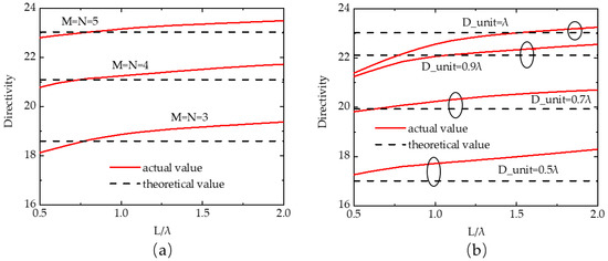
Figure 1.
Directivity of a uniform rectangular array with different length of the element: (a) equal element spacing along the axes (x, y), (b) equal element number .
3. Antenna Design and Analysis
3.1. Surface Wave End-fire Antenna Element
A new surface-wave antenna array that has high directivity and high aperture efficiency is designed based on the three-dimensional aperture principle. The element antennas are low-profile end-fire antennas based on the surface wave. The electromagnetic waves excited by a low-profile capacity structure are transformed into surface waves traveling along the longitudinal direction of the dielectric slab. Then, the electromagnetic waves radiate into free space at the termination of the slab. The structure of the antenna operating at 6 GHz is shown in Figure 2. The element antenna is composed of ground, a dielectric slab, a metal disc, a feeding probe, and a shorting pin. The dielectric slab is processed from aluminum nitride whose relative dielectric constant is 8.8 and loss tangent is 0.
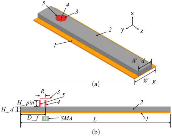
Figure 2.
Structure of the low profile surface-wave antenna: (a) main view, (b) side view.
The different slab lengths are simulated to analyze the influence of slab length on the antenna gain. The results are shown in Figure 3. Lr in the figure is the front part length of the dielectric slab that can be expressed as The gain monotonically increases when the length of the dielectric slab is between 0.5λ and 2.5λ. The maximum gain is about 10 dBi. Because of the dielectric loss, the gain of the antenna will reduce when Lr is longer than 2.5λ. Besides this, the overlong Lr may cause impedance mismatching.
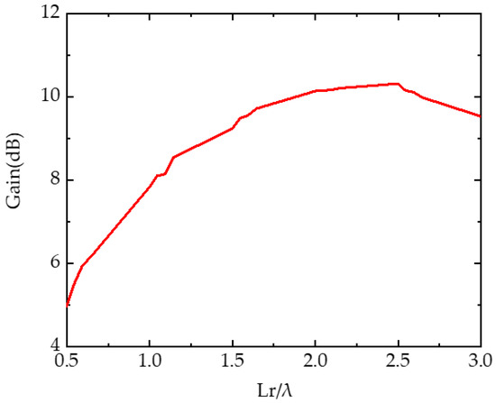
Figure 3.
Simulated end-fire gain of the proposed antenna with different lengths.
The optimized size parameters are shown in Table 1. R_pin is the radius of the shorting pin. The antenna performance was evaluated using the Finite Element Method (FEM) in ANSYS HFSS. Figure 4a shows the simulated radiation patterns of the designed element antenna operating at 6 GHz. The simulated gain in the end-fire direction is 9.5 dBi. The 3-dB beam width of the antenna is 45° in H-plane and 40° in E-plane. Because of the finite ground, the beam direction is offset upward in the E-plane and the offset angle is 11°. It can be seen that the front-to-back ratio is about 13 dB. Figure 4b reports the reflection coefficient (S11) whose bandwidth is from 5.8 GHz to 6.4 GHz defined through frequencies with a reflection coefficient lower than −10 dB. As shown in Figure 4c, an electric field exists as a surface wave and propagates forward in the longitudinal direction. Because the surface wave in the dielectric slab mostly propagates in TM0 mode, the maximum energy of the E-field is bound on the upper surface of the dielectric slab. Meanwhile, because of the finite lateral size of the dielectric slab, a small amount of E-filed energy radiates from the dielectric slab during propagation. Besides this, the E-field excited by the feeding probe cannot be completely converted into a surface wave. Thus, the radiation of the proposed antenna includes three parts, radiation from the feeding probe, radiation from the dielectric slab, and radiation from the termination of the dielectric slab. The radiation pattern of the proposed antenna is not only related to the cross-section of the dielectric slab but also related to the length of the dielectric slab.

Table 1.
Detailed dimension of the designed element antenna.
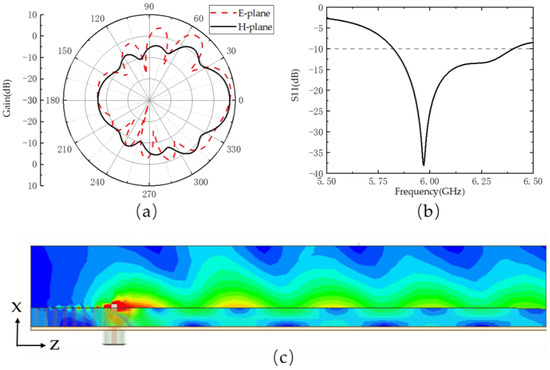
Figure 4.
(a) Simulated E-plane and H-plane radiation patterns of the element antenna. (b) Simulated reflection coefficient of the element antenna. (c) E-field distribution in the dielectric slab and free space.
3.2. High Efficiency 3 × 3 Array
Then, using the above antenna as elements, we proposed a novel two dimension 3 × 3 antenna array with high gain and high aperture efficiency based on the three-dimensional aperture principle. The configuration of the proposed array operating at 6 GHz is shown in Figure 5. The nine-element antennas are fixed to a metal plate with the back of their ground. Two rectangular holes are set so that the coaxial cables can cross the metal plate. According to the three-dimensional aperture principle and [17], the array obtains the maximum gain when element spacing is about 0.9λ and the maximum aperture efficiency when
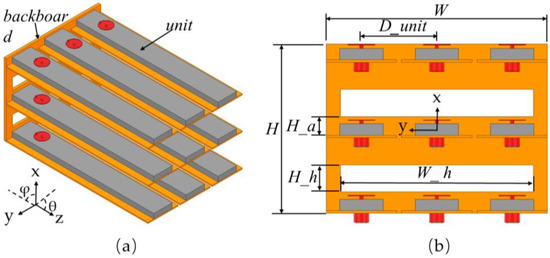
Figure 5.
Configuration of the proposed antenna array: (a) main view, (b) front view.
The effect of element spacing on the performance of the array is simulated and the results shown in Figure 6 are in good agreement with the theoretical prediction. The black solid line and red solid line indicate the gain and the aperture efficiency of the array, respectively. The maximum aperture efficiency of the array is 120% when the element spacing is 0.5λ and the maximum gain is 17.8 dBi with the element spacing being about 0.9λ. Optimal aperture efficiency and optimal gain cannot be obtained at the same time. The results demonstrate that reducing element spacing can improve aperture efficiency.
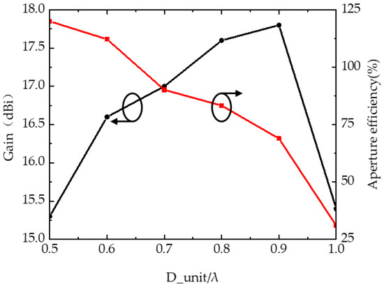
Figure 6.
The simulated gain and aperture efficiency of the proposed array with different element spacing Black: Gain, Red: Aperture efficiency.
The optimized dimensions of the array are as follows: , and For this array, is unequal to the area of its radiation aperture. The physical aperture of the array is Owing to the element spacing being 0.5λ, the actual radiation aperture should be calculated by Equation (2).
The proposed antenna array is simulated in ANSYS HFSS and the results are shown in Figure 7. The gain of the array is 15.3 dBi and the directivity (D) is 33.9 according to the conversion relation between gain and directivity. D is substituted in Equation (6) to obtain the proposed array and the equivalent aperture efficiency is figured out to be about 120% relative to the two-dimension aperture. The proposed array obtains a directivity that is greater than that calculated by the two-dimensional aperture principle, which indicates the accuracy of the proposed three-dimensional aperture principle. We designed and fabricated a linear array based on the three-dimensional aperture principle in a previous paper [11] and the ultra-high aperture efficiency of the array based on the principle was validated preemptively. Figure 7b shows the simulated E-plane and H-plane radiation patterns of the proposed array. The 3-dB beam width of the antenna is 30° in H-plane and 34° in E-plane.
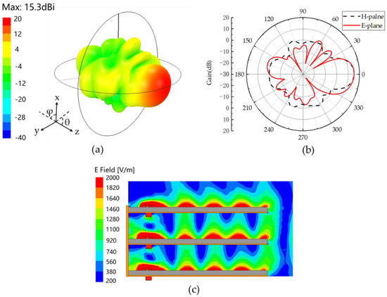
Figure 7.
(a) Simulated 3D radiation pattern of the proposed array. (b) Simulated E-plane and H-plane radiation patterns of the proposed array. (c) E-field distribution in XOZ plane.
Figure 7c shows the E-field distribution in the XOZ plane. Though the element spacing is small the electromagnetic wave in the antenna remains a surface wave. The electric field will damp rapidly outside the dielectric slab due to the characteristic of the surface wave so that the metal ground above has little impact on the element antenna below. Even so, the wave velocity of the surface wave in the lower dielectric slab is slower than that in the dielectric slab. To make the surface waves in all dielectric slabs in-phase when they propagate to the terminal, the excitation of the topside antennas is set at a 5° phase delay to keep the beam pointing at the z-axis.
As exhibited in Table 2, compared with the existing high aperture efficiency antennas including arrays, horn antennas, and other aperture antennas, the proposed antenna array has the highest aperture efficiency. Meanwhile, the proposed array is simple in structure and easy to manufacture.
Table 2.
Comparison of two dimension aperture efficiency between the proposed array with other aperture antennas.
4. Conclusions
This paper proposed a novel three-dimensional aperture principle applying to high aperture efficiency arrays consisting of surface wave end-fire antenna elements. According to the proposed principle, the gain of an array could be increased not only by increasing the area of the array but also by extending the longitudinal length of the array elements. Meanwhile, a 3 × 3 array operating at 6 GHz is proposed to verify the principle above. The proposed array is consisting of low-profile surface wave antennas. The aperture efficiency attains 120%, which is higher than the existing designs for similar purposes. The range of optional applications of the high aperture efficiency arrays based on the three-dimensional aperture principle is extremely extensive. The sectional area of mobile platforms is normally limited and the high gain large aperture antennas are unable to install in these platforms. The three-dimensional aperture principle proposed in this paper proves that with the same aperture, the proposed array can obtain higher gain than traditional aperture antennas, which indicates this type of array is highly suitable for mobile platforms such as aircraft and missiles.
Author Contributions
Conceptualization, K.P.; Data curation, K.P., Y.X. and L.D.; Funding acquisition, P.W.; Investigation, K.P. and Y.X.; Methodology, K.P., Y.X., L.D. and P.W.; Project administration, Y.X. and P.W.; Software, L.D.; Validation, P.W.; Visualization, P.W.; Writing—original draft, P.W.; Writing—review and editing, Y.X. and L.D. All authors have read and agreed to the published version of the manuscript.
Funding
This work is supported by the National Key Research and Development Program of China (2020YFB1807400), National Natural Science Foundation of China (61571022, 61971022, 61801376) National Key Laboratory of Science and Technology on Space Microwave (6142411032201), Postdoctoral Fellows of “Zhuoyue” Program and National Key Laboratory Foundation of China (HTKJ2019KL504013, 61424020305).
Data Availability Statement
The data presented in this study are available on request from the corresponding author.
Conflicts of Interest
The authors declare no conflict of interest.
References
- Das, S.; Mandal, D.; Kar, R.; Ghoshal, S.P. A Generalized Expression of Directivity for Planar Antenna Arrays. In Proceedings of the 2013 Annual IEEE India Conference (INDICON), Mumbai, India, 13–15 December 2013; pp. 1–3. [Google Scholar]
- Deng, N.; Haenggi, M. A Novel Approximate Antenna Pattern for Directional Antenna Arrays. IEEE Wirel. Commun. Lett. 2018, 7, 832–835. [Google Scholar] [CrossRef]
- Das, S.; Mandal, D.; Ghoshal, S.P.; Kar, R. Generalization of Directivity Expressions for Antenna Arrays. IEEE Trans. Antennas Propag. 2017, 65, 915–919. [Google Scholar] [CrossRef]
- Wu, Y.-W.; Hao, Z.-C.; Miao, Z.-W. A Planar W-Band Large-Scale High-Gain Substrate-Integrated Waveguide Slot Array. IEEE Trans. Antennas Propag. 2020, 68, 6429–6434. [Google Scholar] [CrossRef]
- Abdel-Wahab, W.M.; Al-Saedi, H.; Raeis-Zadeh, M.; Alian, E.H.M.; Ehsandar, A.; Chen, G.; Palizban, A.; Ghafarian, N.; El-Sawaf, H.; Nezhad-Ahmadi, M.R.; et al. Affordable Large Scale Active-Phased Array Antenna for Ka-Band Mobile SATCOM Applications. In Proceedings of the 2019 13th European Conference on Antennas and Propagation (EuCAP) 2019, Krakow, Poland, 31 March–5 April 2019; Volume 4. [Google Scholar]
- Wei, C.; Zhang, Z.-Y.; Wu, K.-L. Phase Compensation for Decoupling of Large-Scale Staggered Dual-Polarized Dipole Array Antennas. IEEE Trans. Antennas Propag. 2020, 68, 2822–2831. [Google Scholar] [CrossRef]
- Wang, B.; Zhao, Z.; Sun, K.; Tao, T.; Yang, X.; Yang, D. Low-Profile High-Aperture-Efficiency Air-Filled Substrate Integrated Cavity Antenna Array. Antennas Wirel. Propag. Lett. 2022, 21, 1442–1446. [Google Scholar] [CrossRef]
- Tao, Z.; Jiang, W.X.; Ma, H.F.; Cui, T.J. High-Gain and High-Efficiency GRIN Metamaterial Lens Antenna With Uniform Amplitude and Phase Distributions on Aperture. IEEE Trans. Antennas Propag. 2018, 66, 16–22. [Google Scholar] [CrossRef]
- Gholami, M.; Amaya, R.E.; Yagoub, M.C.E. A Compact and High-Gain Cavity-Backed Waveguide Aperture Antenna in the C-Band for High-Power Applications. IEEE Trans. Antennas Propag. 2018, 66, 1208–1216. [Google Scholar] [CrossRef]
- Kang, E.; Hur, J.; Seo, C.; Lee, H.; Choo, H. High Aperture Efficiency Array Antenna for Wireless Power Transfer Applications. Energies 2020, 13, 2241. [Google Scholar] [CrossRef]
- Dai, L.; Xie, Y.; Wang, H.; Wu, P. Three-Dimensional Aperture Principle for End-Fire Radiation Antenna Array. AIP Adv. 2021, 11, 025116. [Google Scholar] [CrossRef]
- Dai, L.; Xie, Y.; Wang, H. A Low-Profile End-Fire Conformal Surface Wave Antenna with Capacitive Feed Structure. Sensors 2020, 20, 7054. [Google Scholar] [CrossRef] [PubMed]
- Zucker, F.J. Surface-Wave Antennas. In Antenna Engineering Handbook, 4th ed.; Volakis, J.L., Ed.; McGraw Hill: New York, NY, USA, 2007; pp. 263–265. [Google Scholar]
- Andersen, J.B. Radiation from surface-wave antennas. Electron. Lett. 1967, 3, 251–252. [Google Scholar] [CrossRef]
- Forman, B.J. A Novel Directivity Expression for Planar Antenna Arrays. Radio Sci. 1970, 5, 1077–1083. [Google Scholar] [CrossRef]
- Zucker, F.J. Theory and Applications of Surface Waves. Nuovo Cim. 1952, 9, 450–473. [Google Scholar] [CrossRef]
- Southworth, G.C. Certain factors affecting the gain of directive antennas. Bell Syst. Tech. J. 1931, 10, 63–95. [Google Scholar] [CrossRef]
- Sandhu, A.I.; Arnieri, E.; Amendola, G.; Boccia, L.; Meniconi, E.; Ziegler, V. Radiating Elements for Shared Aperture Tx/Rx Phased Arrays at K/Ka Band. IEEE Trans. Antennas Propag. 2016, 64, 2270–2282. [Google Scholar] [CrossRef]


Publisher’s Note: MDPI stays neutral with regard to jurisdictional claims in published maps and institutional affiliations. |
© 2022 by the authors. Licensee MDPI, Basel, Switzerland. This article is an open access article distributed under the terms and conditions of the Creative Commons Attribution (CC BY) license (https://creativecommons.org/licenses/by/4.0/).