Abstract
The hybrid AC-DC microgrid (MG) has gained popularity recently as it offers the benefits of AC and DC systems. Interconnecting AC-DC converters are necessary since the MG has both DC and AC sub-grids. Adding an extra harmonic adjustment mechanism to the interlinking converters is promising because non-linear AC loads can worsen the quality of the voltage on the AC bus. The interlinking converters’ primary function is to interchange real and reactive power between DC and AC sub-grids, so the typical harmonic controlling approach implemented for active power filters (APFs) might not be appropriate for them. When the MG’s capacity is high, it is desirable that the switching frequency be lesser than the APFs. The performance of harmonic correction or even system stability may suffer at low switching frequencies. In this study, a harmonic compensating technique appropriate for hybrid AC-DC interlinking converters with lower switching frequencies is planned. The suggested strategy, modeling techniques, stability analysis, and a thorough virtual impedance design are discussed in this work.
1. Introduction
Power quality (PQ) difficulties arise when distributed generation (DG) systems, such as solar photovoltaic (PV), wind turbine (WT), fuel cells (FC), and diesel engine generator (DEG), are integrated into the current distribution network [1,2,3,4]. In order to facilitate the integration of DGs, loads, and energy storage systems for meeting the energy demand, microgrids (MGs) are built as suitable and flexible platforms [5,6,7]. The microgrid is one of the promising energy sources which can fulfill a larger percentage of the total electricity demand. Additionally, due to its intermittent nature, it injects substantial unpredictability into the power supply. The PQ, protection, and stability problems in the power sectors will be affected by variations in input sun intensity and wind speed as a result of climatic circumstances. Further, as these resources are inverter-based DG, integrating them will have an impact on the protection strategy used in traditional power systems. Therefore, a very difficult challenge arises in dealing with the PQ problems occurring in a power system under different operating scenarios.
The creation of interfaces to join micro sources in the grid and link the entire MG to the primary grid was a result of the realization of AC MGs. DC MGs are proposed [8,9,10] due to improvements in high-voltage DC technology and an increase in the number of loads using DC rather than AC. The development of DC MG [11,12] is made possible by the existence of reactive power, harmonic current, unbalanced phases, and transformer failures in AC MG. The main advantages of DC MG are that most smart grid objectives could be achieved more quickly, frequently for less money, and more effectively [13,14]. However, since most power grids today are of the AC form and AC MGs continue to have a dominant position [15,16], it is not anticipated that power grids will only see the emergence of purely DC MGs.
To properly exhibit the benefits of AC and DC distribution systems in light of simpler renewable energy integration and improved reliability, a hybrid AC/DC MG or hybrid MG (HMG) [17,18] should be considered. Since DC loads do not directly produce harmonic pollution and interlinking converters with complete controllability can greatly improve PQ, the HMG provides improved PQ in AC grids. An interface converter, whose major purposes are to carefully analyze and integrate the PQ compensation capabilities, including harmonics compensation and unbalance compensation, and maintain energy transfer between the AC bus and DC bus, connects the DC and AC bus of the HMG [19,20,21]. As a result, one of the major issues with running the hybrid system is power management [22,23].
Harmonic pollution is a major concern in HMG [24,25,26] due to the prevalence of switching mode power converters and nonlinear loads. Both passive filters (PF) and active power filters (APF) can be utilized to offer low-impedance routes [27,28] for harmonics, enhancing the PQ of the other nodes in the MG. Due to the widespread character of the harmonics sources, using PF or APF accrues additional costs and is not particularly effective. As a result, the harmonic adjustment in both AC and DC MG can be accomplished via a hybrid active power filter (HAPF) [29,30] in a distributed manner without incurring additional costs. During grid-linked mode and islanded mode [31,32,33], the HAPF is used to deliver active and reactive current while injecting reactive compensatory current to increase PQ.
This literature describes an HMG with a shunt HAPF in this context, which functions as an interlinking converter. Different conventional techniques [34], like p-q theory, synchronous reference frame theory, instant values of current components (ID-IQ Method), instantaneous inactive power in coordinates p-q-r, synchronous detection method, and ADALINE-based algorithms are revealed during the days.
The above algorithms involve the transformation of parameters using standard Park’s and Clark’s transformation techniques; which is a complex and time-consuming process.
In [35] the techniques like the least mean square (LMS), least mean fourth (LMF) D-LMS, leaky least means square forth (LLMF) and normalized least mean fourth (NLMF) are discussed. These controllers worked well in harmonic environments and with the distorted grid. Failures at DC offset and unsuitability for grid synchronization with RES applications are the main shortcomings of the aforementioned controllers.
However, in some works [36,37], the authors proposed the Gauss-Newton approaches and their easier versions. But these methods are not employed for PQ compensation in three-phase, three/four-wire systems.
In this work, the MRGN technique is analyzed with the Fuzzy Adaptive Grasshopper Optimization Algorithm (FAGOA) [38] for generating the reference currents.
The key benefits of MRGN are its rapid, precise, and efficient methodology, which enables quick response in dynamic environments. To evaluate the states of non-linear systems, the FAGOA filter, an intelligent adaptive unscented Kalman filter, is employed. The suggested approach combines an evolutionary computation with an adaptive unscented Kalman filter. The computation upgrades the potential solutions using fuzzy logic. The adaptive unscented Kalman filter’s parameters are adjusted using the suggested optimization approach.
Similarly, for switching signals, the inverter employs various control strategies. Some common methods [39] are the Hysteresis current controller (HCC) and adaptive hysteresis current controller (AHCC). But, the shortcoming of HCC is that the difference in switching frequency is inside a specific band which is uneven. Similarly in AHCC, higher switching loss will arise in the network as a result of the high switching frequency.
Therefore in this work, the Fuzzy Adaptive Hysteresis Current Controller (FAHCC) [39] method is employed to control the modulation frequency, minimize switching loss, and create an adaptive hysteresis band. In the proposed method, FLC calculates the hysteresis bandwidth.
Additionally, to sustain the DC link voltage of the HAPF, adaptive fuzzy logic control (AFLC) [40] is employed for tracking the maximum power from solar PV and WT systems. Even though, the conventional FLC is frequently used due to its simple and easy design. However, it still has certain drawbacks, such as the inability to locate an exact amount of MPP. Low irradiation makes FLC unsuitable for operation and causes high oscillations. In order to improve the PV system performance, the proposed AFLC is provided. Compared to other conventional approaches, the proposed method has a simple design and produces findings that are more accurate. The performance of the MPPT approach offers enhancement, stable operation, quick convergence, reduced oscillation, and increased effectiveness. With smooth and little ripple, the suggested AFL-MPPT approach produces correct PV system output power. Moreover, the proposed AFL-MPPT touches a steady state within a very less time period.
Finally, the performance of the controllers is analyzed using MATLAB/Simulink, and the outcomes are confirmed using a real-time experimental setup. The proposed control strategy is found to have greater adaptability and dependability, as well as superior filtering capabilities than traditional techniques.
The main goals of this literature are to:
- Design an HMG with a suitable intelligent MPPT technique for PV and WT systems.
- Enhance the PQ by compensating the harmonics and reactive power in both grid and islanded modes by using AI techniques.
- Use the proposed HAPF connected to the hybrid MG integrated power system to deliver total harmonic distortion (THD) values below the IEEE-519 standard tolerance of 5%.
- Offer a faster and more reliable harmonic correction technique in order to produce the reference current.
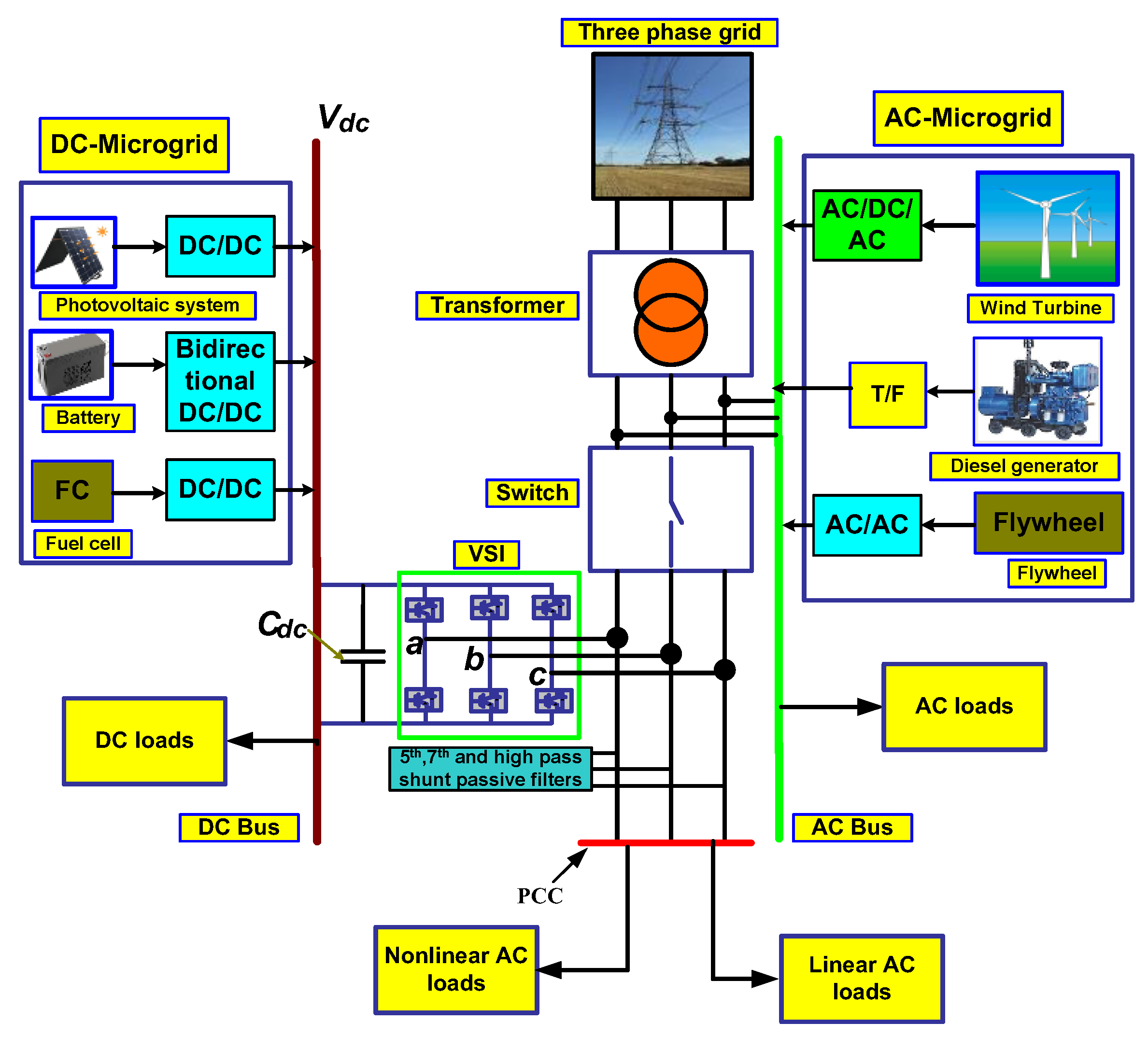
2. System Configuration
To improve the PQ, an HMG with DC and AC local loads interfaced with shunt HAPF is proposed in this research effort. Figure 1 shows the HMG with various DGs (PV, BESS, FC on the DC side; WT, DEG, and FW on the AC side) connected across both the DC and AC buses via DC/DC, DC/AC, and AC/DC/AC converters. To achieve PQ performance through grid-connected and islanded modes, a circuit breaker switch is connected before the HAPF. By activating the DC integration mode, the objective of the presented method is to protect the PQ of MGs from any negative effects. When utility power is stable, the AC integration is activated to boost the MG’s efficiency. The battery source is powered by a bidirectional DC/DC converter. The AC/DC/AC converter is used by distributed generating sources like wind turbines. Through a transformer, the diesel generators are directly connected to the AC bus. Transformers and AC/AC converters connect AC energy storages, such as flywheels, to the AC grid. The hybrid filter functions as a DC to AC MG interlinking converter. The PCC is where the linear and non-linear AC loads are coupled. The AC grid has a voltage of 440 V. In order to isolate the supply grid system from any power disturbances that may arise in the system, the three-phase supply system is fed to the linear and nonlinear AC loads at the Point of Intersection (POI). The incorporation of AC/DC allows for the analysis of HAPF performance. The operation of the proposed techniques is assured under grid-connected and islanded modes.
Figure 1.
Proposed system.
3. Control Strategy
The performance of the MG-integrated hybrid active power filter (HAPF) is determined by the control strategy chosen. The AFL-MPPT technique is employed in this paper to track the maximum power from PV and WT. The MRGN method employs the Fuzzy Adaptive Grasshopper Optimization Algorithm to estimate reference current generation (FAGOA). The FAHCC is used to generate the gating signal. The detailed design of FAHCC is discussed below.
3.1. Fuzzy Adaptive Grasshopper Optimization Algorithm
FAGOA is a swarm optimization-based variant of the Grasshopper Optimization Algorithm (GOA). This algorithm is based on the characteristics of grasshoppers in their natural habitat. Grasshoppers gathered to form the largest swarms, which met for exploration and exploitation. Fuzzy logic is used in the proposed FAGOA for computing the update factor for every single candidate’s solution. The procedure to find an optimal solution to ease a function is briefed in the subsequent stages:
Step 1: Set the grasshoppers as:
where the ith grasshopper candidate is presented by . The term and are the lower and upper search space boundaries that provide the possible minimum and maximum solution values for the proposed issue, is a random number in (0; 1) and N is the number of grasshoppers.
Step 2: Evaluate the decreasing factor for the new generation as:
where, ‘’ and ‘’ are denoted as current and maximum iterations respectively. The minimum and maximum values of are given by and respectively.
Step 3: Create new representatives by:
And
where, and are the effects of energy sources, the intensity of attraction, and the attractive length scale, respectively. The function is the social forces between individuals, is the distance between ith and xth agents.
Step 4: Keep track of the performance of potential solutions and select the best one.
Step 5: The best solution is to go back to the original circumstances for termination, otherwise, move on to step 2. Each agent will now carry out two additional tasks with the introduction of a new FAGOA:
where, and are global and local priority factors for ith agent at iteration f respectively.
The characteristics of the local and global priority factors serve as the foundation for the declining factor.
The fuzzy logic is implemented to evaluate for updating the agents. Hence, in Equation (5), the updating factor is replaced and can be expressed as:
where is the new fuzzy updating factor. The fuzzy logic design receives , as inputs, as the output. The FLC module is developed using Mamdani-based fuzzy rules.
Define rule , and N is the number of rules, which is expressed as:
where, are the fuzzy sets.
where, EW: extra weak, VW: very weak, W: weak, Z: Zero, S: Small, VS: very small, ES: extra small. The parameters are the relating MFs. And are crisp degrees of membership of with their respective term sets.
Each rule results in the following clipped MF:
where is crisp and is fuzzy. Table I depict corresponding fuzzy rules and employed to evaluate the decreasing factor. The aggregation over all rules leads to:
As the aggregation is still a fuzzy MF, it is required to defuzzify to obtain a crisp decreasing factor. Therefore, defuzzification leads to:
The integrals in Equation (6) run from 0 to .
Now consider that the calculated factor, which is presented by and its maximum value is set as and its value is updated as:
For every evolutionary algorithm, it is required to evaluate the fitness function which is given as:
and
where to is the simulation step time and n is the number of states in the non-linear system. The suggested approach aims to find the ideal parameter during the working time. The proposed algorithm’s pseudo code is displayed in Algorithm 1.
| Algorithm 1. Pseudo code of FAGOA. | |
| Fuzzy Adaptive Grasshopper OptimizationAlgorithm (FAGOA) | |
| 1: | Initialization: Create the first generation of grasshoppers, and measure the fitness function of each individual |
| 2: | Find the best member and label it as “Gbest ” |
| 3: | while m < Max iteration do |
| 4: | for each search agent do |
| 5: | Measure global and local importance factors |
| 6: | Calculate decreasing factor using FLC to measure decreasing factor.(F; t) based on global and local priority factors |
| 7: | Revise the search agent using Equation (12) |
| 8: | end for |
| 9: | Update “Gbest” |
| 10: | m = m + 1 |
| 11: | end while |
| 12: | Return “Gbest” |
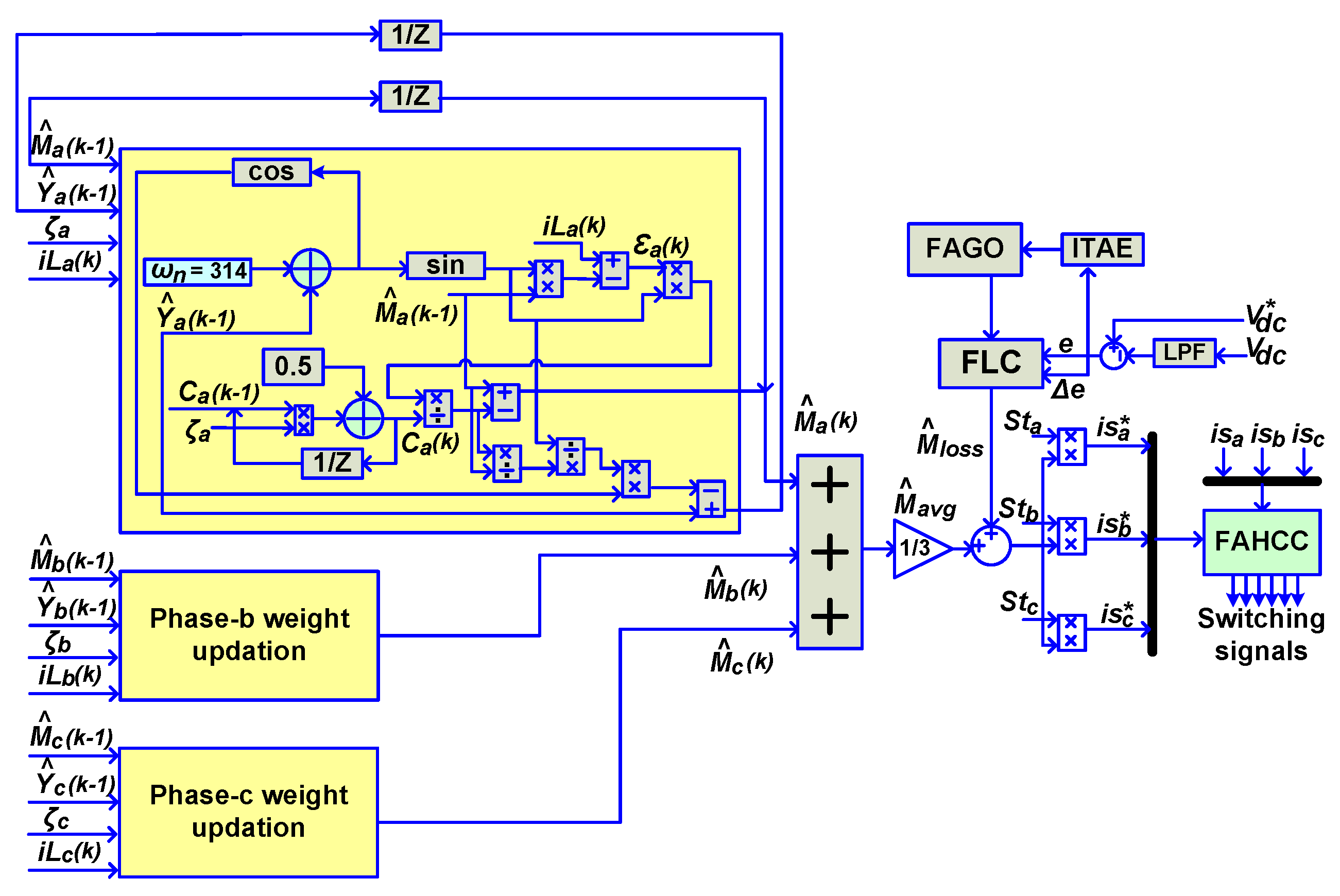
3.2. Modified Recursive Gauss-Newton Method
The conventional RGN is a complicated technique that requires large memory for repetitive computations. Whereas, MGRN is less complex as compared to the original method. The detailed analysis of the MRGN technique is explained below:
Let a sinusoidal current in a power system is considered as:
where, in, Mn, ωn, Yn,, Xn and n represent the current’s peak value, instantaneous value, frequency, phase shift, zero mean white noise, and harmonic order.
The fundamental and harmonic quantities that make up the current in a nonlinear system. A model of the error equation is required to compute the magnitude (Mn) and phase (Yn) of certain current harmonics.
The error equation model is expressed as:
ε(k) is an error at kth instant, i(k) is the total current at kth instant.
Again,
where,
where,
The exponentially weighted cost function to obtain is given as
where, is the exponentially weighted cost function, ζ is the forgetting factor, and value is within (0,1). Putting the value of from (12) in (14) we have.
Since the error is stated in the form Y = AX + BU, so the computing of (14) applying the standard LS method is,
where,
and is presented as a Hessian matrix.
Updated estimation of is expressed as:
Now using the modified MRGN method, the hessian matrix is updated as
Taking, as a constant term, the inverse Hessian matrix is computed as:
where,
Now the updated estimation of is expressed as:
The three-phase fundamental current component is measured as follows:
3.2.1. Generation of Fundamental Reference Magnitude of Current
The fundamental maximum reference current magnitude of each phase is evaluated in terms of . In order to determine the effective fundamental magnitude , all the fundamental magnitudes are averaged for generating the reference current, which corresponds to the active power demand of the system from the grid.
3.2.2. Calculations of Switching Losses
HAPF has active switching losses; therefore, it is required to reduce the switching loss . The switching loss is computed by obtaining the error from the DC link voltage and reference DC link voltage which is then processed through the PI controller. The fundamental magnitude for reference generation current is expressed as:
3.2.3. Generation of Switching Signals
The attained from (26) is multiplied by in-phase synchronizing templates to produce reference currents essential for pulse-width modulation (PWM) control of VSI. The phase synchronizing templates at the PCC is given as:
where, , and are instantaneous three-phase supply voltages, and
The reference currents are produced by multiplying synchronizing templates to fundamental magnitude .
A comparison between the reference and detected grid currents are done through PWM and necessary gating pulses are generated. The control block diagram of the proposed technique is illustrated in Figure 2.
Figure 2.
The control block of the proposed MRGN technique, where and are the dc link reference voltage and three phase reference currents respectively.
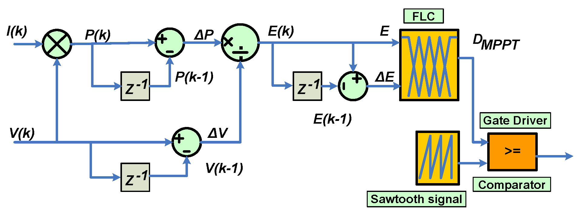
3.3. AFL−MPPT Method
Due to its simplicity, ability to deal with system nonlinearity, and lack of data regarding mathematical modeling, fuzzy logic (FL) control has seen significant improvements in a variety of applications. The tracking behavior of solar PV panels is highly complicated as a result of uncertain characteristics and climatic conditions. Tracking the MPP using FL−based MPPT is straightforward to accomplish and requires less data. Fuzzification, rule assessment, and defuzzification are three phases that can be used to operate the FL control’s performance. For computing the input MFs of the MPPT controller during the first stage, changes estimated in the output voltage and current of PV are used. The accuracy of the controller is determined by the quantity of input MFs. The control approach is chosen in the second stage using FL linguistic rules. Here, various fuzzy MFs are used to allocate the input and output of the FL controller. The defuzzification in the FL controller, which takes place in the third stage, is how the future value of an output MF is determined. The components for error (E) and change in error () are inputs to the FL MPPT controller.
The (E) and () are calculated as,
where and determines the present and previous samples of the PV, and determines the estimated current and previous samples of the PV output voltage, respectively. and determines the current and previous samples of the error variable, respectively. and values are calculated with the measured output power and voltage of the solar panel. Positive large (POL), positive medium (POM), positive small (POS), zero (Z), negative small (NES), negative medium (NEM), and negative large (NEL) are the seven different fuzzy subsets that make up the variable inputs and output MFs (NEL). As a result, the AFL−MPPT approach uses a total of 49 fuzzy control rules to implement the algorithm. In Table 1, the rules for how the proposed AFL-MPPT approach links the input and output MFs are presented. Figure 3 displays the AFL-MPPT method’s schematic diagram. Triangular MF is established in this method for both input and output MFs due to the ease of their application using inexpensive digital controller devices. Based on the table, 49 IF−THEN fuzzy rules have been used to explain the AFL-MPPT approach.
Table 1.
Fuzzy rule base.
Figure 3.
Circuit Schematic diagram of the AFL−MPPT method.
4. Results and Discussion
Through simulation tests carried out in the MATLAB/ Simulation environment and validated in real-time using dSPACE constructed in the lab, the performance of the proposed MG in the grid−attached and islanded settings as well as during the transition between them is explored.
4.1. Grid Connected Mode
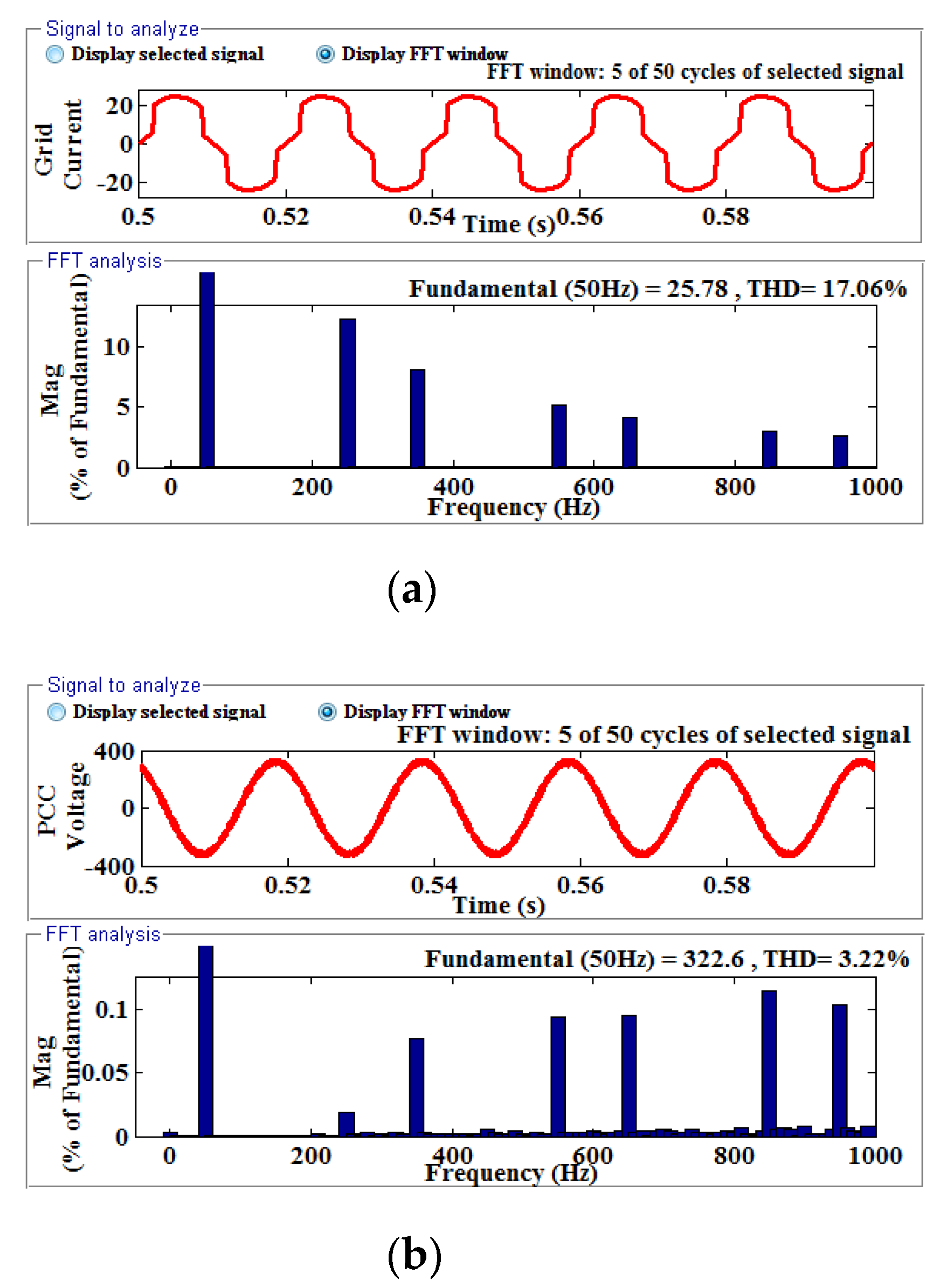
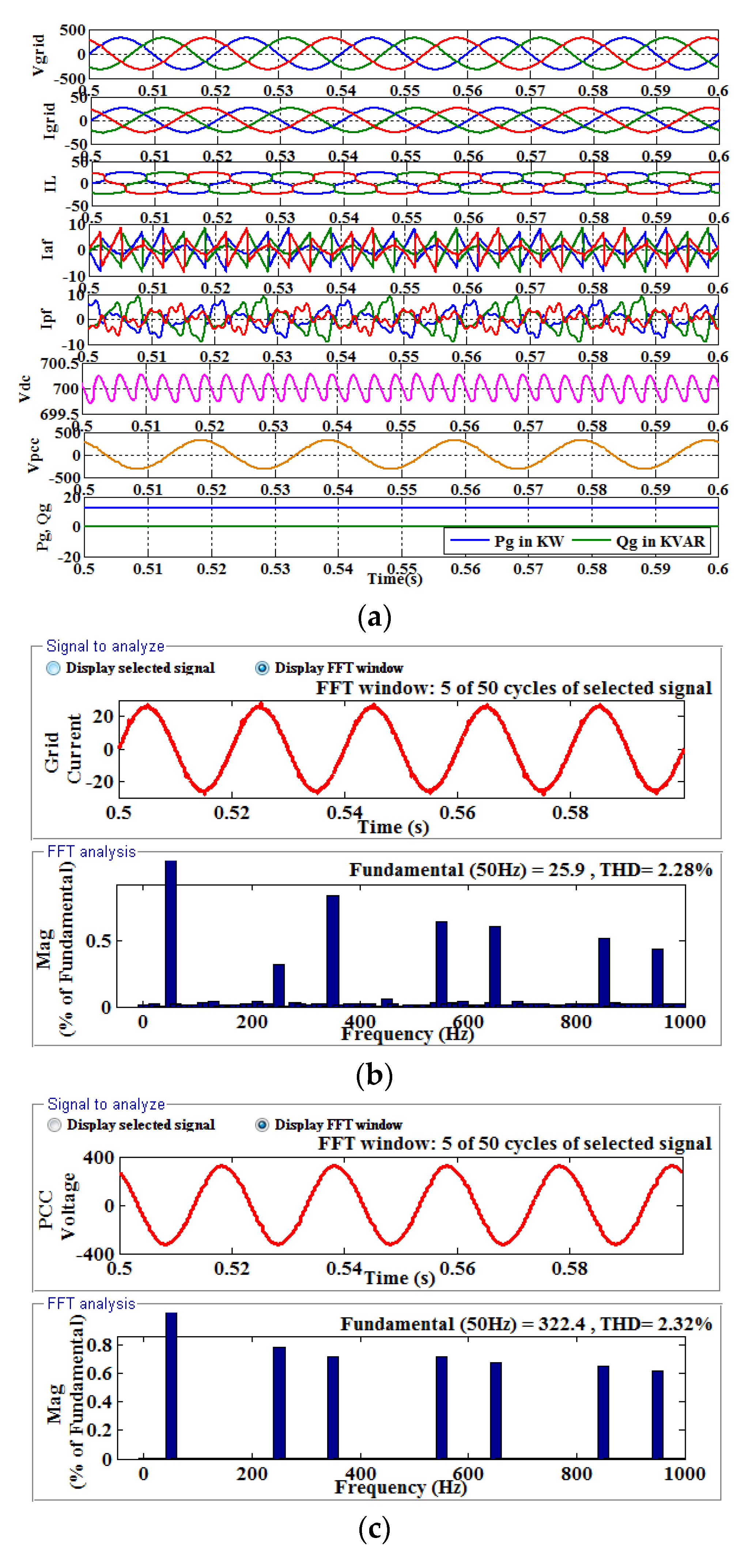
4.1.1. Steady State Analysis Using Inductive Load
In this section, the grid−connected AC/DC MG is used with a nonlinear inductive load without any filtering. The non-linear properties of the load are found to cause the load current to be distorted, and the calculated THD is 17.06%. Figure 4a,b demonstrates, respectively, the harmonic analysis of the PCC voltage and the distorted load current.
Figure 4.
(a) FFT analysis of distorted load current/grid current with inductive load, (b) FFT analysis of PCC voltage with inductive load.
The proposed HAPF is then connected to the system, and the AC/DC MG is configured to operate in grid-connected mode with an inductive load. Figure 5 depicts the grid voltage and current, load current, injected active filter current, injected passive filter current, DC link voltage, PCC voltage, active and reactive power drawn from the grid by an inductive load connected at PCC. According to the findings, the HAPF injects the necessary compensating current to improve grid current and PCC voltage. Figure 5a−c displays the different waveforms under inductive load, as well as the FFT analysis of grid current and PCC voltage. Grid current and PCC voltage THD are calculated to be 2.28% and 2.32%, respectively.
Figure 5.
(a) Grid voltage and current, Load current, Injected active filter current, Injected passive filter current, DC link voltage, PCC voltage, Active and Reactive power drawn from the grid by the load connected at PCC for inductive load in grid-connected mode, (b) FFT analysis of compensated grid current with inductive load, and s(c) FFT analysis of compensated PCC voltage with inductive load.
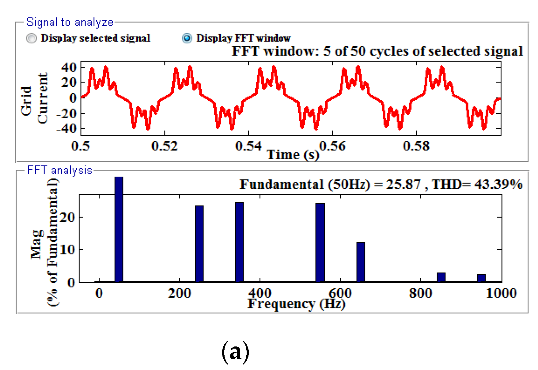
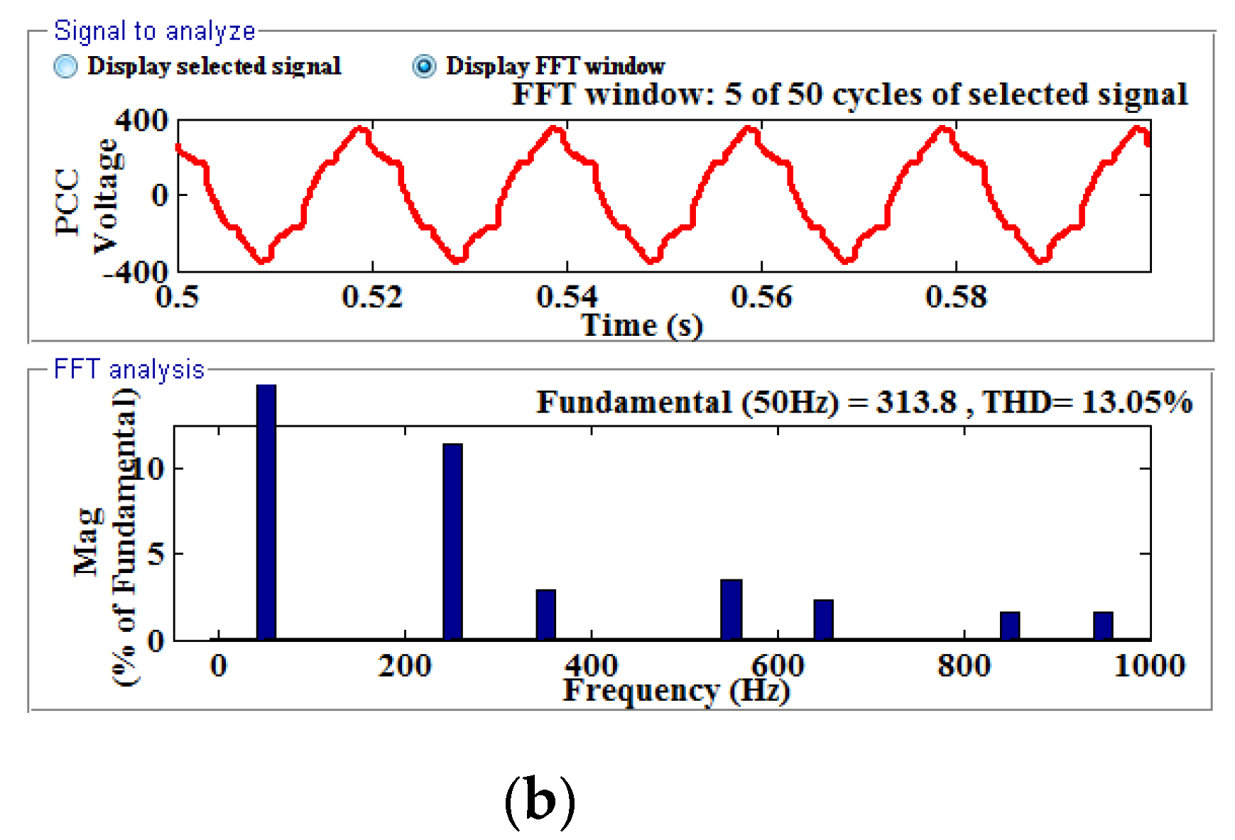
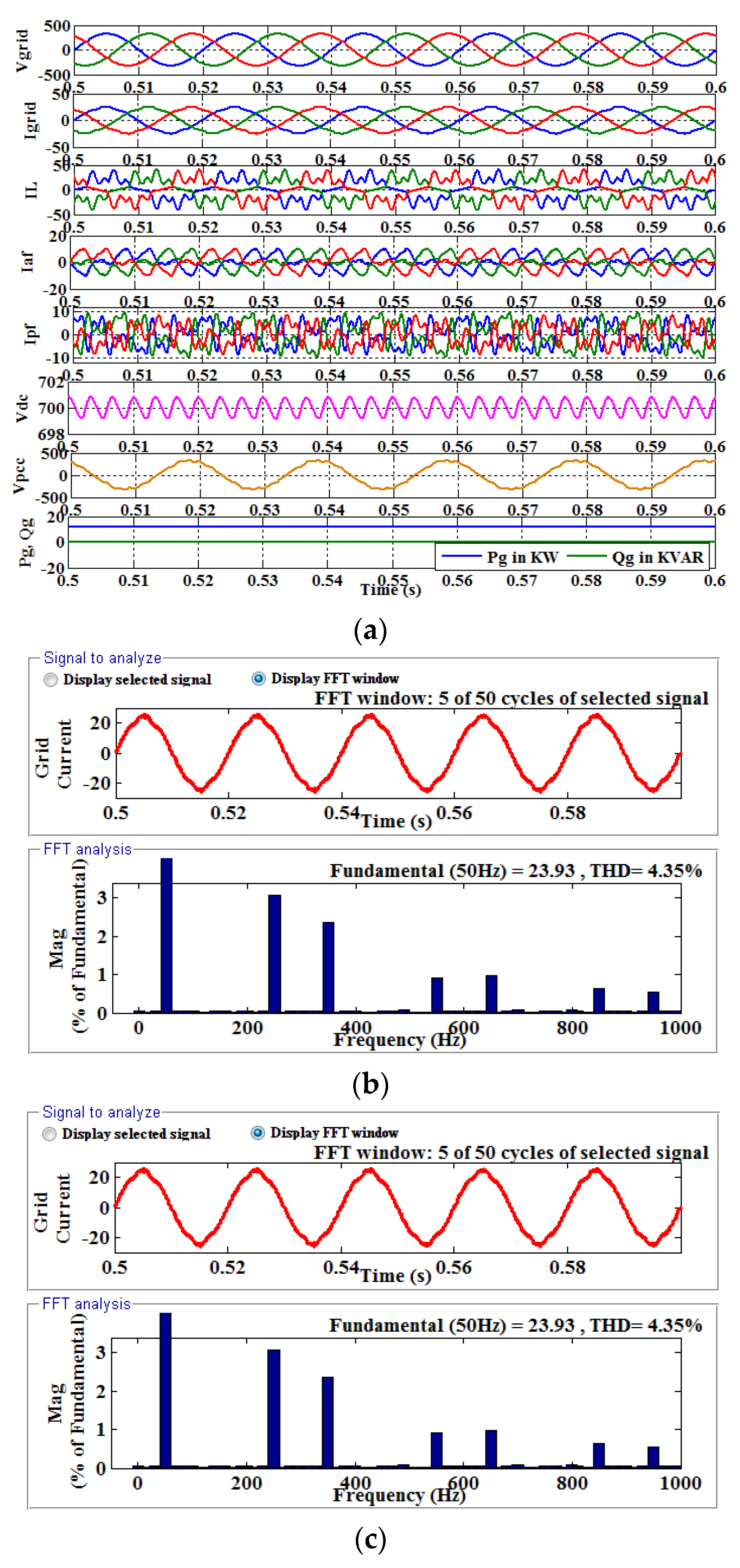
4.1.2. Steady State Analysis Using Capacitive Load
Under non−linear capacitive loading conditions, the AC/DC MG is operated in the grid-linked mode without any filters. The load current is found to be highly distorted because of the influence of non-linear load in this case. The THD is 43.39% because there is no filtering action. Figure 6a,b shows the harmonic analysis of the distorted load current and the PCC voltage.

Figure 6.
(a) FFT analysis of distorted load current/grid current with a capacitive load, and (b) FFT analysis of PCC voltage with capacitive load.
The proposed MRGNN−based HAPF is then connected to the system in grid-connected mode with a capacitive load, and the grid voltage, grid current, load current, injected active filter current, injected passive filter current, DC link voltage, PCC voltage, active and reactive power drawn from the grid by the load under capacitive load are revealed in Figure 7a. The HAPF significantly improves grid current and PCC voltage by injecting the required compensating current. Figure 7a,b show the FFT analysis of grid current and PCC voltage, respectively. Grid current THD and PCC voltage THD are calculated to be 4.35% and 4.86%, respectively.
Figure 7.
(a) Grid voltage and current, Load current, Injected active filter current, Injected passive filter current, DC link voltage, PCC voltage, Active and Reactive power drawn from the grid by the load connected at PCC for capacitive load in grid-connected mode, (b) FFT analysis of compensated grid current with a capacitive load, and (c) FFT analysis of compensated PCC voltage with capacitive load.
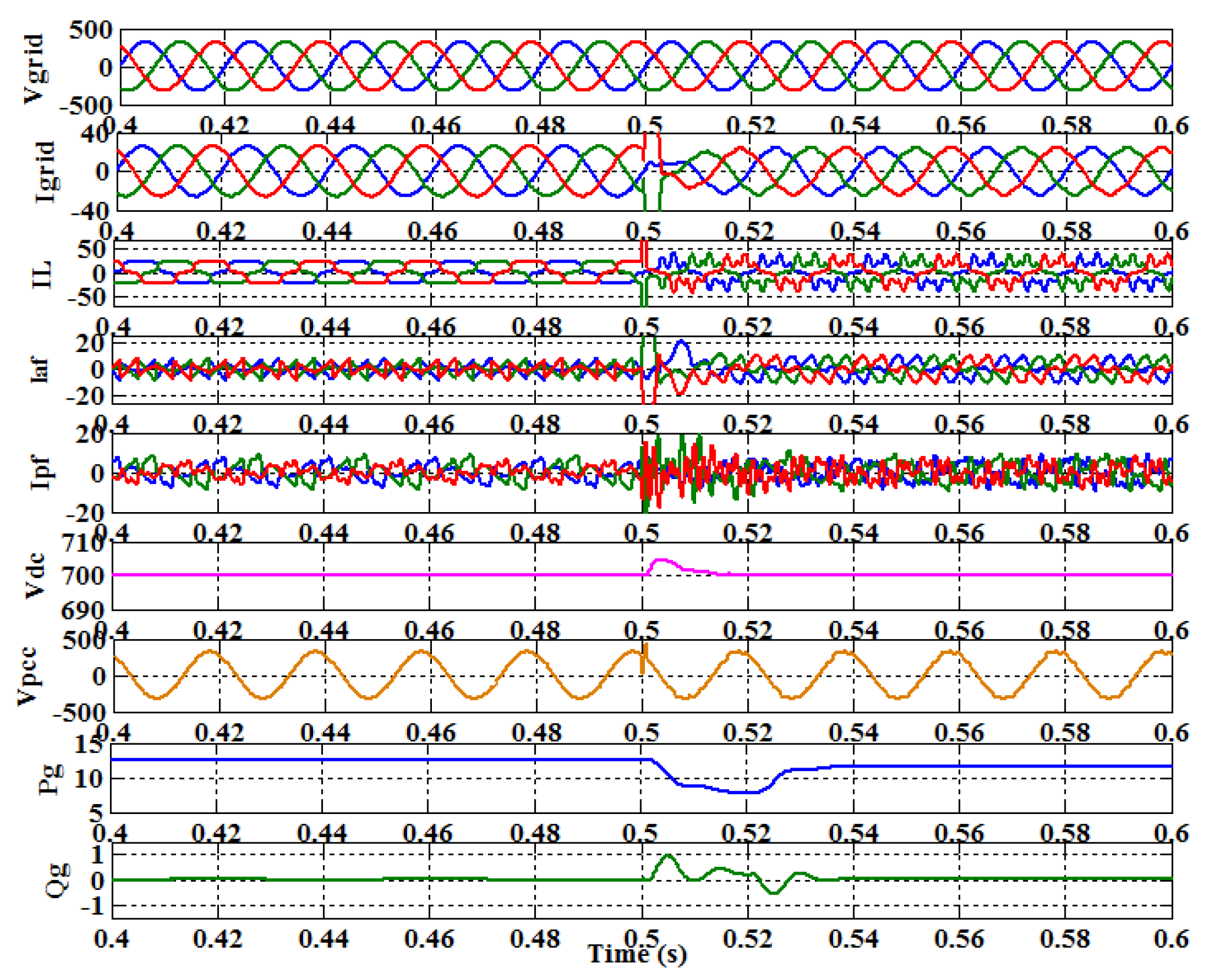
4.1.3. Transient Analysis
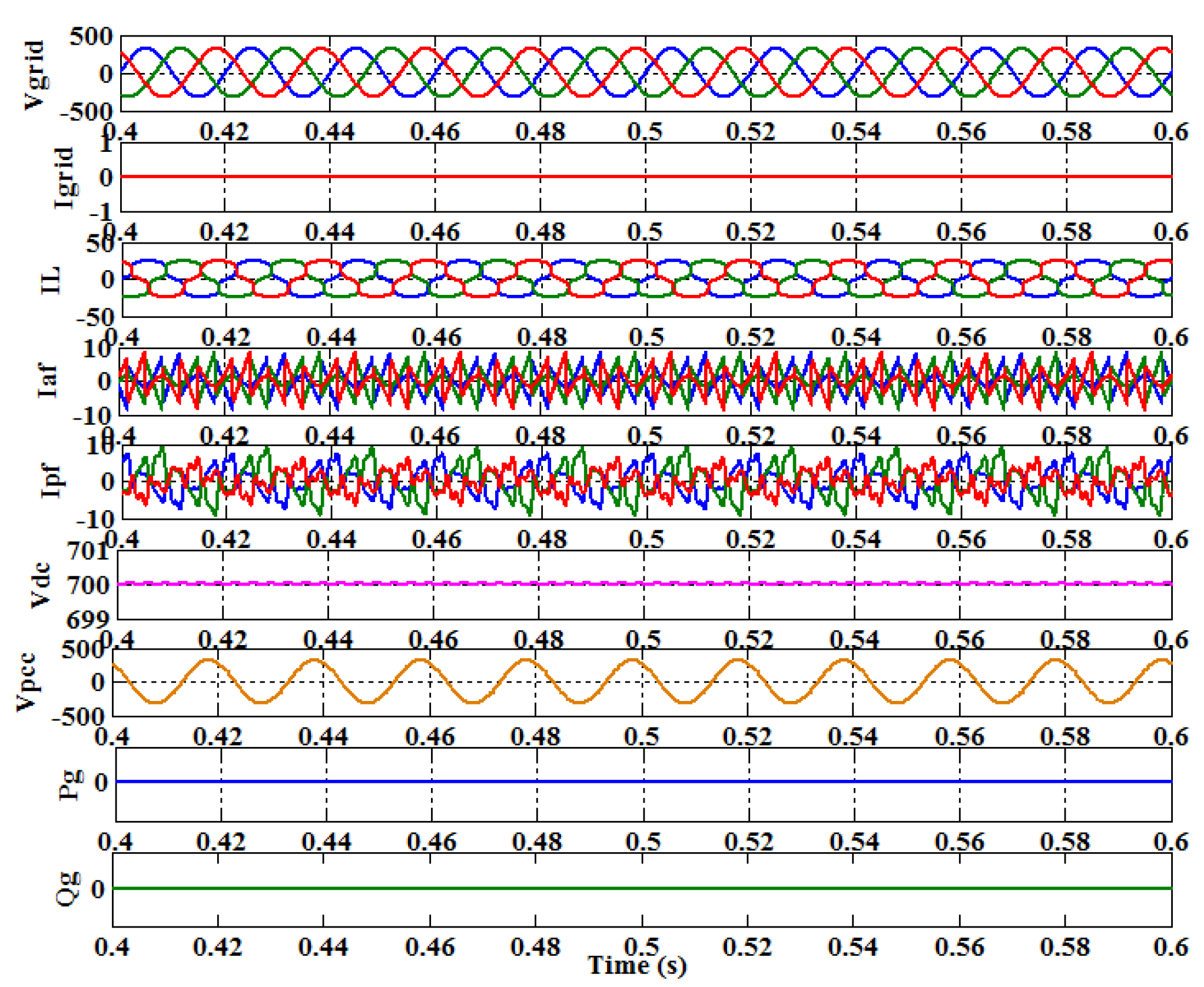
By switching from inductive to capacitive load at 0.5 s, the dynamic response of the system using the proposed HAPF is obtained. Figure 8 depicts various waveforms obtained during the transient analysis. When inductive to capacitive switching occurs, a reactive power exchange occurs between the grid and the load, as revealed in the diagram, and the DC link voltage rises during the transient period before settling at the reference value. When the transient period is over, the grid’s reactive power is zero, and the hybrid filter is the only source of reactive power.
Figure 8.
Grid voltage and current, Load current, Injected active filter current, Injected passive filter current, DC link voltage, PCC voltage, Active and Reactive power drawn from the grid by the load connected at PCC of the system when switching from inductive to capacitive load in grid-connected mode.
4.2. Islanded Mode
The main grid is isolated in this mode, and the grid interfacing inverter supplies both active and reactive power to the load coupled at the PCC, allowing the voltage at the PCC to be sinusoidal. The analysis is performed using a diode bridge rectifier (DBR) with R = 40 ohm and L = 100 mH under a non-linear inductive load. Because the grid is isolated in this mode, the inductive load draws no grid current. Again, no active or reactive power is drawn from the grid. Figure 9 depicts the load current, DC link voltage, filter currents, and PCC voltage under inductive load in islanded mode. The figure shows that even though the grid is isolated from the AC/DC MG, the harmonics in the PCC voltage are compensated by the HAPF. This demonstrates the performance of the proposed MRGN-based HAPF in both grid-connected and islanded modes with varying loading conditions.
Figure 9.
Grid voltage and current, Load current, Injected active filter current, Injected passive filter current, DC link voltage, PCC voltage, and Active and Reactive power drawn from the grid by the load connected at PCC for inductive load in islanded mode.
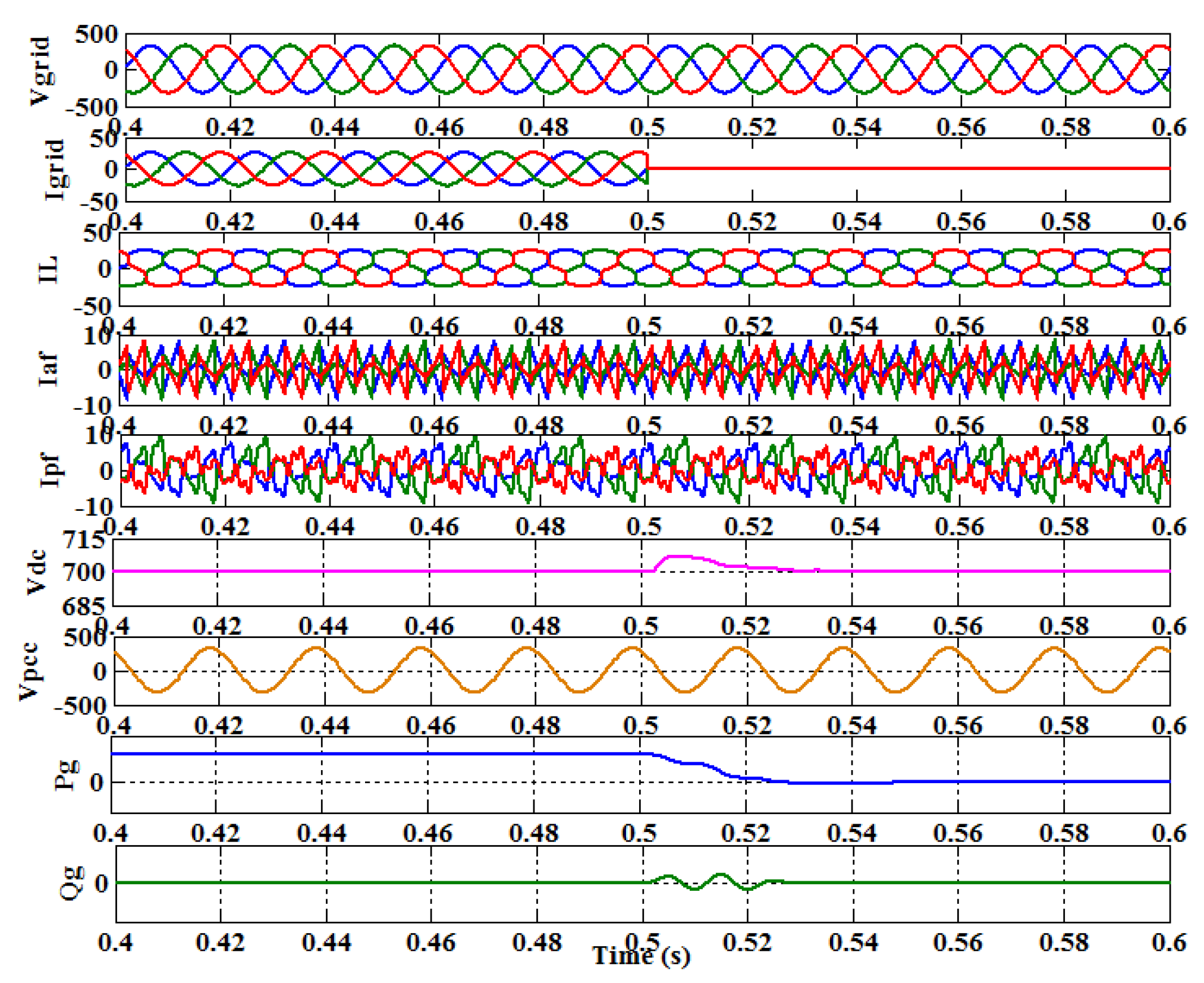
4.3. Operation from the Grid to Islanded Mode
The system is simulated to examine the performance of the proposed HAPF under nonlinear inductive loading conditions using a diode bridge rectifier (DBR) with R = 40 ohm and L = 100 mH. At 0.5 s, the main grid is intentionally isolated. Figure 10 depicts various waveforms of grid voltage and current, load current, injected active and passive filter currents, DC link voltage, PCC voltage, and active and reactive power received from the grid by the load. When switching from grid to islanded mode, the grid current is observed to be zero. The DC link voltage, active and reactive powers are affected during the switching process and are then established. Table 2 demonstrates the various parameters such as THD, real and reactive powers, and power factors with and without the proposed HAPF under various loading conditions. When the proposed HAPF is incorporated into the power system, the THD values and power factors are significantly improved.
Figure 10.
Grid voltage and current, Load current, Injected active filter current, Injected passive filter current, DC link voltage, PCC voltage, Active and Reactive power drawn from the grid by the load connected at PCC when switching from grid connected to islanded mode.
Table 2.
Performance parameters obtained in simulation in grid-connected mode.
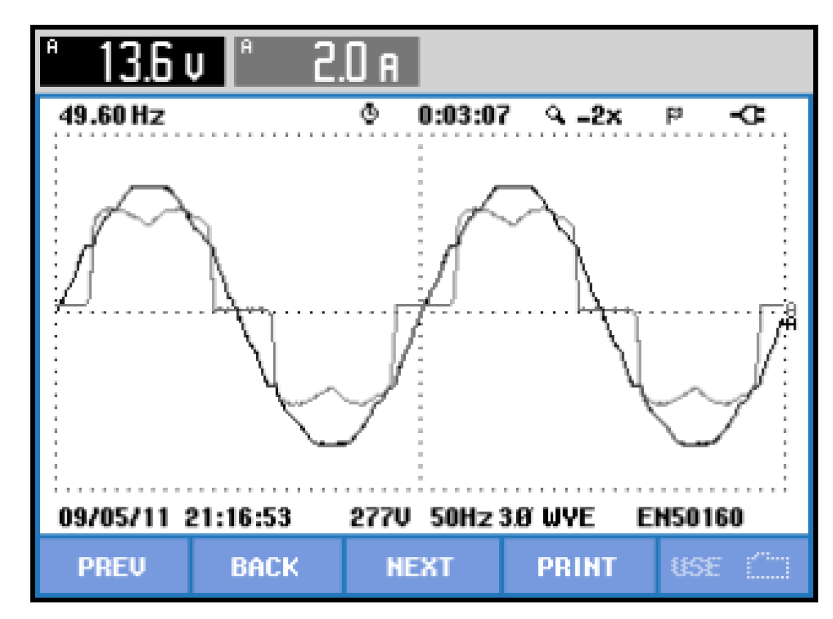
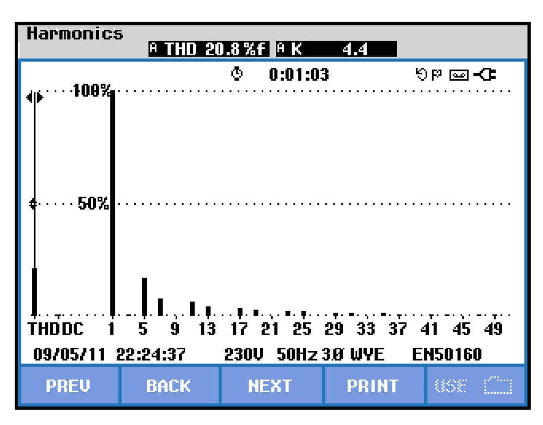
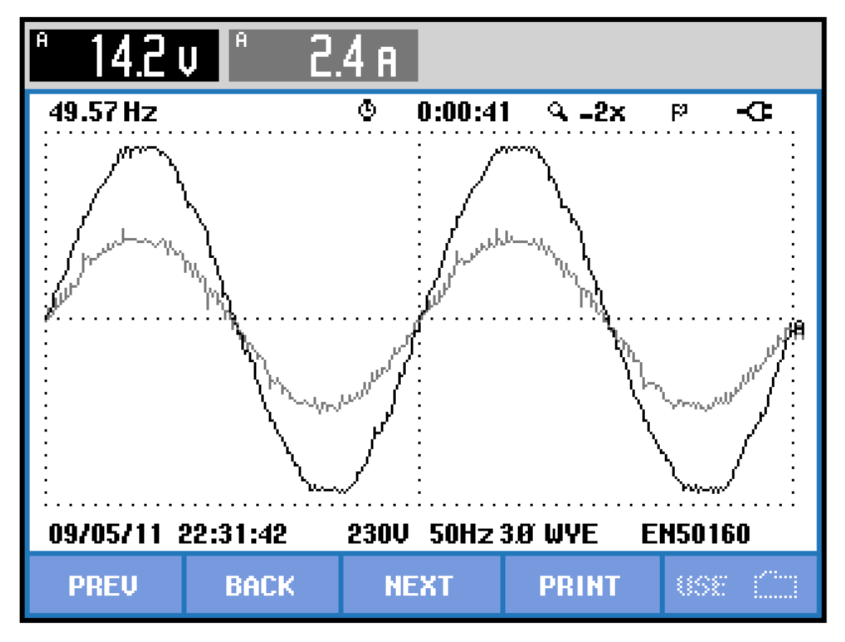
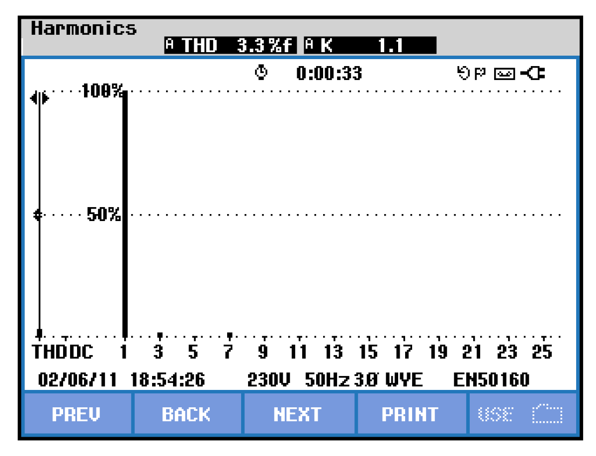
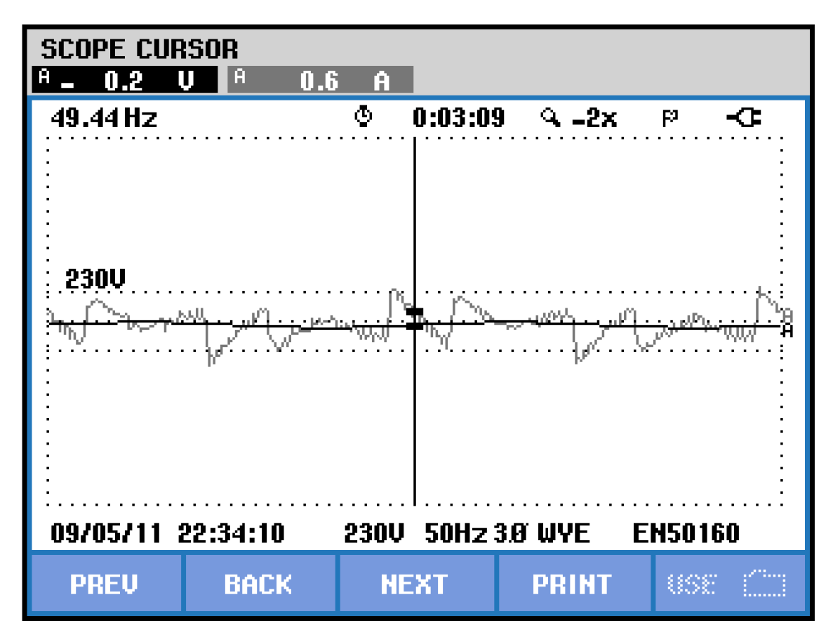
4.4. Real-Time Analysis
The performance of the proposed techniques with the hybrid microgrid system is analyzed with dSPACE (DS1202) platform kit with the same system parameters as in the simulation. For the real-time analysis, a programmable ac supply is employed to signify the source grid and is incorporated with an emulated microgrid. The real-time setup includes an uncontrolled diode bridge rectifier (acting as nonlinear load), Semikron power converter, Hall-Effect current (LA-55p), and voltage (LV-25) sensors are employed for detecting all signals and filter inductor. During the integration of renewable sources in AC form, a three-phase HAPF is employed. Additionally, for MPPT operation, AFL MPPT is employed, which runs the boost converter. For suppressing the harmonics and switching ripples, the RC filter and interfacing inductors are used. A multi-meter (Fluke-115) is engaged for measuring the voltage and current. PQ analyzers (Fluke-43B; Hioki-3100) are implemented for the detection of several harmonic spectra. The system is tested in different loading conditions. The performance of the grid voltage and current with inductive load and without any filtering action is shown in Figure 11. The FFT analysis of distorted grid current with inductive load and without any filtering action is illustrated in Figure 12. Using the proposed methodology the characteristics of voltage and current using non-linear inductive load is noticed in Figure 13. The FFT analysis of compensated grid current with inductive load is illustrated in Figure 14. Under grid-connected mode, the Injected filter current is illustrated in Figure 15.
Figure 11.
Grid voltage and current with inductive load and without any filtering action.
Figure 12.
FFT analysis of distorted grid current with inductive load and without any filtering action.
Figure 13.
Grid voltage and current for inductive load in grid-connected mode.
Figure 14.
FFT analysis of compensated grid current with inductive load.
Figure 15.
Injected filter current in grid-connected mode.
5. Conclusions
The proposed MRGN-based HAPF’s performance is assessed in an AC-DC MG integrated power system network under grid-connected, islanded and transition from the grid to the islanded modes of operation. The simulations are run under various loading conditions and inverter switching states. Under the aforementioned operating conditions, the DC MG efficiently stabilizes the DC link voltage of the proposed HAPF’s VSI. Under different operating scenarios, the compensating performance of the proposed MRGN-based HAPF improved significantly with the integration of AC and DC MGs.
Author Contributions
Conceptualization, S.R.D., A.K.M., S.R.S. and S.-C.K.; methodology, S.R.D., P.K.R. and S.R.S.; software, A.K.M., S.R.S. and P.K.R.; validation, S.R.D., S.R.S. and S.-C.K.; formal analysis, S.R.D., A.K.M. and S.-C.K.; investigation, S.R.D., P.K.R. and S.-C.K.; resources, P.K.R., S.R.S., S.-C.K.; data curation, S.R.D. and S.R.S.; writing—original draft preparation, S.R.D., A.K.M. and S.-C.K.; writing—review and editing, S.R.D., A.K.M. and S.-C.K.; visualization, S.R.S., P.K.R. and S.-C.K.; supervision, S.R.D., S.R.S.; project administration, A.K.M., S.-C.K. and S.R.S.; funding acquisition, S.R.S. and S.-C.K. All authors have read and agreed to the published version of the manuscript.
Funding
This research was funded by WOOSONG UNIVERSITY’s (Daejeon, Republic of Korea) Academic Research Funding—2022.
Data Availability Statement
Not applicable.
Conflicts of Interest
The authors declare no conflict of interest.
References
- Chawda, G.S.; Shaik, A.G.; Shaik, M.; Padmanaban, S.; Holm-Nielsen, J.B.; Mahela, O.P.; Kaliannan, P. Comprehensive Review on Detection and Classification of Power Quality Disturbances in Utility Grid With Renewable Energy Penetration. IEEE Access 2020, 8, 146807–146830. [Google Scholar] [CrossRef]
- Lakum, A.; Mahajan, V. Optimal placement and sizing of multiple active power filters in radial distribution system using grey wolf optimizer in presence of nonlinear distributed generation. Electr. Power Syst. Res. 2019, 173, 281–290. [Google Scholar] [CrossRef]
- Stanelyte, D.; Radziukynas, V. Review of Voltage and Reactive Power Control Algorithms in Electrical Distribution Networks. Energies 2019, 13, 58. [Google Scholar] [CrossRef]
- Oladeji, I.; Makolo, P.; Abdillah, M.; Shi, J.; Zamora, R. Security Impacts Assessment of Active Distribution Network on the Modern Grid Operation—A Review. Electronics 2021, 10, 2040. [Google Scholar] [CrossRef]
- Subramanian, V.; Indragandhi, V.; Kuppusamy, R.; Teekaraman, Y. Modeling and Analysis of PV System with Fuzzy Logic MPPT Technique for a DC Microgrid under Variable Atmospheric Conditions. Electronics 2021, 10, 2541. [Google Scholar] [CrossRef]
- Gholami, M.; Pilloni, A.; Pisano, A.; Usai, E. Robust Distributed Secondary Voltage Restoration Control of AC Microgrids under Multiple Communication Delays. Energies 2021, 14, 1165. [Google Scholar] [CrossRef]
- Tauqeer, H.A.; Saeed, F.; Yousuf, M.H.; Ahmed, H.; Idrees, A.; Khan, M.H.; Gelani, H.E. Proposed model of sustainable resource management for smart grid utilization. World Electr. Veh. J. 2021, 12, 70. [Google Scholar] [CrossRef]
- Bhagavathy, S.M.; Pillai, G. PV Microgrid Design for Rural Electrification. Designs 2018, 2, 33. [Google Scholar] [CrossRef]
- Liang, X.; Andalib-Bin-Karim, C. Harmonics and Mitigation Techniques Through Advanced Control in Grid-Connected Renewable Energy Sources: A Review. IEEE Trans. Ind. Appl. 2018, 54, 3100–3111. [Google Scholar] [CrossRef]
- Prabaharan, N.; Palanisamy, K. A comprehensive review on reduced switch multilevel inverter topologies, modulation techniques and applications. Renew. Sustain. Energy Rev. 2017, 76, 1248–1282. [Google Scholar] [CrossRef]
- El-Shahat, A.; Sumaiya, S. DC-microgrid system design, control, and analysis. Electronics 2019, 8, 124. [Google Scholar] [CrossRef]
- Das, S.R.; Ray, P.K.; Sahoo, A.K.; Ramasubbareddy, S.; Babu, T.S.; Kumar, N.M.; Alhelou, H.H.; Siano, P. Performance of Hybrid Filter in a Microgrid Integrated Power System Network Using Wavelet Techniques. Appl. Sci. 2020, 10, 6792. [Google Scholar] [CrossRef]
- Lotfi, H.; Khodaei, A. AC versus DC microgrid planning. IEEE Trans. Smart Grid 2015, 8, 296–304. [Google Scholar] [CrossRef]
- Beheshtaein, S.; Cuzner, R.M.; Forouzesh, M.; Savaghebi, M.; Guerrero, J.M. DC microgrid protection: A comprehensive review. IEEE J. Emerg. Sel. Top. Power Electron. 2019. [Google Scholar] [CrossRef]
- Mohammed, A.; Refaat, S.S.; Bayhan, S.; Abu-Rub, H. AC microgrid control and management strategies: Evaluation and review. IEEE Power Electron. Mag. 2019, 6, 18–31. [Google Scholar] [CrossRef]
- He, L.; Li, Y.; Guerrero, J.M.; Cao, Y. A Comprehensive Inertial Control Strategy for Hybrid AC/DC Microgrid With Distributed Generations. IEEE Trans. Smart Grid 2019, 11, 1737–1747. [Google Scholar] [CrossRef]
- Eghtedarpour, N.; Farjah, E. Power control and management in a hybrid AC/DC microgrid. IEEE Trans. Smart Grid 2014, 5, 1494–1505. [Google Scholar] [CrossRef]
- Rizvi, S.; Abu-Siada, A. Active Power Sharing in a Micro-Grid with Multiple Grid Connections. Designs 2022, 6, 24. [Google Scholar] [CrossRef]
- Moradzadeh, A.; Zakeri, S.; Shoaran, M.; Mohammadi-Ivatloo, B.; Mohammadi, F. Short-Term Load Forecasting of Microgrid via Hybrid Support Vector Regression and Long Short-Term Memory Algorithms. Sustainability 2020, 12, 7076. [Google Scholar] [CrossRef]
- Dawood, F.; Shafiullah, G.; Anda, M. Stand-Alone Microgrid with 100% Renewable Energy: A Case Study with Hybrid Solar PV-Battery-Hydrogen. Sustainability 2020, 12, 2047. [Google Scholar] [CrossRef]
- Ambia, M.N.; Al-Durra, A.; Caruana, C.; Muyeen, S. Power management of hybrid micro-grid system by a generic centralized supervisory control scheme. Sustain. Energy Technol. Assessments 2014, 8, 57–65. [Google Scholar] [CrossRef]
- Khatibzadeh, A.; Besmi, M.; Mahabadi, A.; Haghifam, M.R. Multi-Agent-Based Controller for Voltage Enhancement in AC/DC Hybrid Microgrid Using Energy Storages. Energies 2017, 10, 169. [Google Scholar] [CrossRef]
- Dey, B.; Márquez, F.P.G.; Basak, S.K. Smart Energy Management of Residential Microgrid System by a Novel Hybrid MGWOSCACSA Algorithm. Energies 2020, 13, 3500. [Google Scholar] [CrossRef]
- Nejabatkhah, F.; Li, Y.W.; Tian, H. Power Quality Control of Smart Hybrid AC/DC Microgrids: An Overview. IEEE Access 2019, 7, 52295–52318. [Google Scholar] [CrossRef]
- Oulis Rousis, A.; Tzelepis, D.; Konstantelos, I.; Booth, C.; Strbac, G. Design of a hybrid AC/DC microgrid using Homer Pro: Case study on an islanded residential application. Inventions 2018, 14, 55. [Google Scholar] [CrossRef]
- Latif, A.; Paul, M.; Das, D.C.; Hussain, S.S.; Ustun, T.S. Price based demand response for optimal frequency stabilization in ORC solar thermal based isolated hybrid microgrid under salp swarm technique. Electronics 2020, 9, 2209. [Google Scholar] [CrossRef]
- Guo, Q.; Xiao, F.; Tu, C.; Jiang, F.; Zhu, R.; Ye, J.; Gao, J. An overview of series-connected power electronic converter with function extension strategies in the context of high-penetration of power electronics and renewables. Renew. Sustain. Energy Rev. 2022, 156, 111934. [Google Scholar] [CrossRef]
- Kumar, M.; Uqaili, M.; Memon, Z.; Das, B. Experimental Harmonics Analysis of UPS (Uninterrupted Power Supply) System and Mitigation Using Single-Phase Half-Bridge HAPF (Hybrid Active Power Filter) Based on Novel Fuzzy Logic Current Controller (FLCC) for Reference Current Extraction (RCE). Adv. Fuzzy Syst. 2022, 2022, 1–18. [Google Scholar] [CrossRef]
- Ray, P.K.; Das, S.R.; Mohanty, A. Fuzzy-controller-designed-PV-based custom power device for power quality enhancement. IEEE Trans. Energy Convers. 2018, 34, 405–414. [Google Scholar] [CrossRef]
- Das, S.R.; Hota, A.P.; Pandey, H.M.; Sahoo, B.M. Industrial power quality enhancement using fuzzy logic based photovoltaic integrated with three phase shunt hybrid active filter and adaptive controller. Appl. Soft Comput. 2022, 121, 108762. [Google Scholar] [CrossRef]
- Ganjian-Aboukheili, M.; Shahabi, M.; Shafiee, Q.; Guerrero, J.M. Seamless Transition of Microgrids Operation From Grid-Connected to Islanded Mode. IEEE Trans. Smart Grid 2019, 11, 2106–2114. [Google Scholar] [CrossRef]
- Wang, Z.; Chen, B.; Wang, J. Decentralized energy management system for networked microgrids in grid-connected and islanded modes. IEEE Trans. Smart Grid 2015, 7, 1097–1105. [Google Scholar] [CrossRef]
- Talapur, G.G.; Suryawanshi, H.M.; Xu, L.; Shitole, A.B. A reliable microgrid with seamless transition between grid connected and islanded mode for residential community with enhanced power quality. IEEE Trans. Ind. Appl. 2018, 54, 5246–5255. [Google Scholar] [CrossRef]
- Martinek, R.; Rzidky, J.; Jaros, R.; Bilik, P.; Ladrova, M. Least Mean Squares and Recursive Least Squares Algorithms for Total Harmonic Distortion Reduction Using Shunt Active Power Filter Control. Energies 2019, 12, 1545. [Google Scholar] [CrossRef]
- Das, S.R.; Mishra, A.K.; Ray, P.K.; Mohanty, A.; Mishra, D.K.; Li, L.; Hossain, M.; Mallick, R.K. Advanced wavelet transform based shunt hybrid active filter in PV integrated power distribution system for power quality enhancement. IET Energy Syst. Integr. 2020, 2, 331–343. [Google Scholar]
- Dash, P.K.; Hasan, S. A fast recursive algorithm for the estimation of frequency, amplitude and phase of noisy sinusoid. IEEE Trans. Ind. Electron. 2011, 58, 4847–4856. [Google Scholar] [CrossRef]
- Chittora, P.; Singh, A.; Singh, M. Gauss–Newton-based fast and simple recursive algorithm for compensation using shunt active power filter. IET Gener. Transm. Distrib. 2017, 11, 1521–1530. [Google Scholar] [CrossRef]
- Asl, R.M.; Palm, R.; Wu, H.; Handroos, H. Fuzzy-based parameter optimization of adaptive unscented Kalman filter: Methodology and experimental validation. IEEE Access 2020, 8, 54887–54904. [Google Scholar] [CrossRef]
- Mishra, A.K.; Ray, P.K.; Mallick, R.K.; Mohanty, A.; Das, S.R. Adaptive fuzzy controlled hybrid shunt active power filter for power quality enhancement. Neural Comput. Appl. 2021, 33, 1435–1452. [Google Scholar] [CrossRef]
- Rezk, H.; Aly, M.; Al-Dhaifallah, M.; Shoyama, M. Design and hardware implementation of new adaptive fuzzy logic-based MPPT control method for photovoltaic applications. IEEE Access 2019, 7, 106427–106438. [Google Scholar] [CrossRef]
Publisher’s Note: MDPI stays neutral with regard to jurisdictional claims in published maps and institutional affiliations. |
© 2022 by the authors. Licensee MDPI, Basel, Switzerland. This article is an open access article distributed under the terms and conditions of the Creative Commons Attribution (CC BY) license (https://creativecommons.org/licenses/by/4.0/).