Review

A Road towards 6G Communication—A Review of 5G Antennas, Arrays, and Wearable Devices

by
Muhammad Ikram
1,*,
Kamel Sultan
1,
Muhammad Faisal Lateef
2 and
Abdulrahman S. M. Alqadami
1
1
School of Information Technology and Electrical Engineering, University of Queensland, Brisbane 4067, Australia
2
School of Science and Engineering, Khazar University, Baku AZ1096, Azerbaijan
*
Author to whom correspondence should be addressed.
Electronics 2022, 11(1), 169; https://doi.org/10.3390/electronics11010169
Submission received: 9 December 2021 / Revised: 1 January 2022 / Accepted: 3 January 2022 / Published: 5 January 2022
(This article belongs to the Special Issue Prospective Multiple Antenna Technologies for 5G and Beyond)

Abstract

:
Next-generation communication systems and wearable technologies aim to achieve high data rates, low energy consumption, and massive connections because of the extensive increase in the number of Internet-of-Things (IoT) and wearable devices. These devices will be employed for many services such as cellular, environment monitoring, telemedicine, biomedical, and smart traffic, etc. Therefore, it is challenging for the current communication devices to accommodate such a high number of services. This article summarizes the motivation and potential of the 6G communication system and discusses its key features. Afterward, the current state-of-the-art of 5G antenna technology, which includes existing 5G antennas and arrays and 5G wearable antennas, are summarized. The article also described the useful methods and techniques of exiting antenna design works that could mitigate the challenges and concerns of the emerging 5G and 6G applications. The key features and requirements of the wearable antennas for next-generation technology are also presented at the end of the paper.

1. Introduction

The global mobile data traffic has been increased dramatically in recent years due to high demand in secure, fast, and large data transmission rates in many recent and advanced applications, including broadcasting, Internet of Things (IoT), automobiles, smart cities, energy, emergencies communication, and wearable devices. This has put a lot of pressure on the current 3G/4G/WiFi wireless communication systems to upgrade their capacity and performance. Each generation of mobile and wireless communication systems has been established to meet those demands. Nevertheless, the data hungry devices used in the above-mentioned applications have increased a lot and require huge data rates [1,2].
One potential way of enhancing capacity and data rates in the current and future mobile and wireless generations is the bandwidth [3,4]. The data rates are directly proportional to the bandwidth. The higher bandwidth provides higher data rates [5,6]. However, current frequency bands, i.e., 1.7 GHz GSM band, 1.8 GHz 4G/LTE band, 2.0 GHz 4G/LTE band, 2.1 LTE band, and 2.6 GHz band, provide limited bandwidth. Recently, high-frequency bands including 24 GHz (n258), 28 GHz (n257 and n261), 37 GHz (n260), and 39 GHz (n260) in addition to some future recommended bands, i.e., 47 and 60 GHz, have been considered for 5G applications [7,8,9,10,11,12,13,14,15,16]. Those high-frequency bands, also called mm-wave bands, can provide significantly large bandwidth (more than 500 MHz). Nevertheless, the current 5G communication still uses the sub-6 GHz band, i.e., 3.3 GHz to 4.2 GHz (n77 and n78), and 4.4 GHz to 5 GHz (n79). The 5G frequency bands are listed in Figure 1. Although some advancements have been accomplished, i.e., use of a more advanced and larger number of multiple-input multiple-output (MIMO) antennas [17,18,19] to improve the wireless communication system, the data rates are still limited due to the narrow bandwidth at sub-6 GHz [6].
In the last few years, substantial work has been presented by considering massive MIMO and mm-wave bands for 5G. In massive-MIMO technology, the implementation of a large number of antennas at both the base station (1000′s of antennas) and handheld devices (10′s of antennas) is required [19,21,22,23]. Multiple antennas of wireless communication systems especially at mmWave and THz provide the ability to considerably improve service quality. However, because acquiring accurate instantaneous channel state information (CSI) can use a significant fraction of bandwidth, the systems that depend on statistical CSI are preferred [24,25].
However, the main challenge is the limited available space, especially in mobile, wearable, and other handheld devices. The current mobile terminals and wearable devices, which operate at several bands, i.e., 3G, 4G, WiFi, and GPS, are already congested and are becoming smarter and more compact. Hence, multiband and more compact antennas are desirable.
In mm-wave communication, the path loss is significantly high [26,27]. Thus, the used antenna should have high directive gain radiation patterns towards the direction of propagation of waves in order to mitigate that path loss. Another big challenge in many applications, i.e., in mobile communication at both microwave and mm-wave bands, is that the direction of communication is not consistent. In other words, the location and orientation of the mobile phone with respect to the base station are unknown. Thus, unprecedented and novel techniques that provide the full antenna beam coverage and stable radiation patterns with higher directive gain are needed. Moreover, in transition to mm-wave 5G communication, 3G/4G/WiFi and sub-6 GHz 5G still exist. Hence, integrated antenna modules using shared aperture antenna structures are also necessary.
Moreover, the coverage area is another important aspect of the recent and future communication system. The 5G systems are ground-based and still unable to provide full coverage with the same amount of data rates for outdoor communications, including air, ocean, and rural or remote areas. Thus, space communication systems, which are complementary to terrestrial communication systems, are expected to integrate with 5G systems to form a fully integrated 6G communication system [2,6,27,28,29], see Figure 2. From the previous mobile transitions where each generation takes almost one decade (i.e., 1G 1980s, 2G 1990s, 3G 2000s, 4G 2010s, 5G 2020s), it is expected that 6G will be applied by 2030 or before due to the development in the transition technologies. The details of an integrated 6G communication system are given in the next section. The structure of the paper is given in Table 1.
Currently, there are many speculations and health concerns related to 5G technology especially at mm-wave bands (>24 GHz). It can be noted that the mm-wave band technology already exists in current systems, i.e., security screening systems at airports, police radar guns, satellites, and remote sensors. Those systems do not cause any health issues. Similarly, in 5G/6G communication systems, there is no evidence available so far for causing any health issues. Nevertheless, the signal attenuation is the main restriction for the communication system at higher frequency bands. Therefore, the suggested solutions can be summarized by antenna systems with very high gain surrounding the handheld device (i.e., MIMO, phased array) or increasing the transmitted power. Therefore, in both scenarios, the impact of the signal on the human body should be a concern. In the previous mobile generations, the specific absorption rate was used to describe this impact. However, with this new frequency range, there is no SAR standard. Therefore, the power density is used to calculate this impact, and it is mentioned and calculated in our previous published paper in [30].

2. Towards 6G Communication System

The 6G communication is already obtaining its conceptual development and shape [1,2,6,27]. Huge demand for data rates has resulted in the transition and upgrade of already in use 5G technology to 6G communication systems with a focus on ultra-low latency, amazing capacity, ultra-high security, and wider coverage of broadcast and mobile within academia and industry. Based on the current literature, the envision communication system of 6G is shown in Figure 2. It typically targets all possible communication scenarios, including terrestrial wireless communication networks, GEO/LEO satellites, intelligent transportation, and massive IoT. It covers large geographical areas, including urban, rural, remote, ocean, and air. The key features of the 6G communication system are discussed in Section 2.1, while they are listed in Figure 3, along with their application scenarios.
It is understood from the current literature that the 6G communication system will be a mixture of sub-6 GHz, mm-wave, and THz bands [2,6,27]. It is further discussed in Section 2.1. Thus, from an antenna design perspective, multiband and shared aperture antennas, which reduce overall antenna footprint, especially in handheld and wearable devices, will be preferred to transmit and receive those wireless signals at those bands. Section 3 and Section 4 discuss the latest published papers targeting sub-6 GHz, mm-wave, and THz bands based on antennas, arrays, and wearable devices.

2.1. Key Features

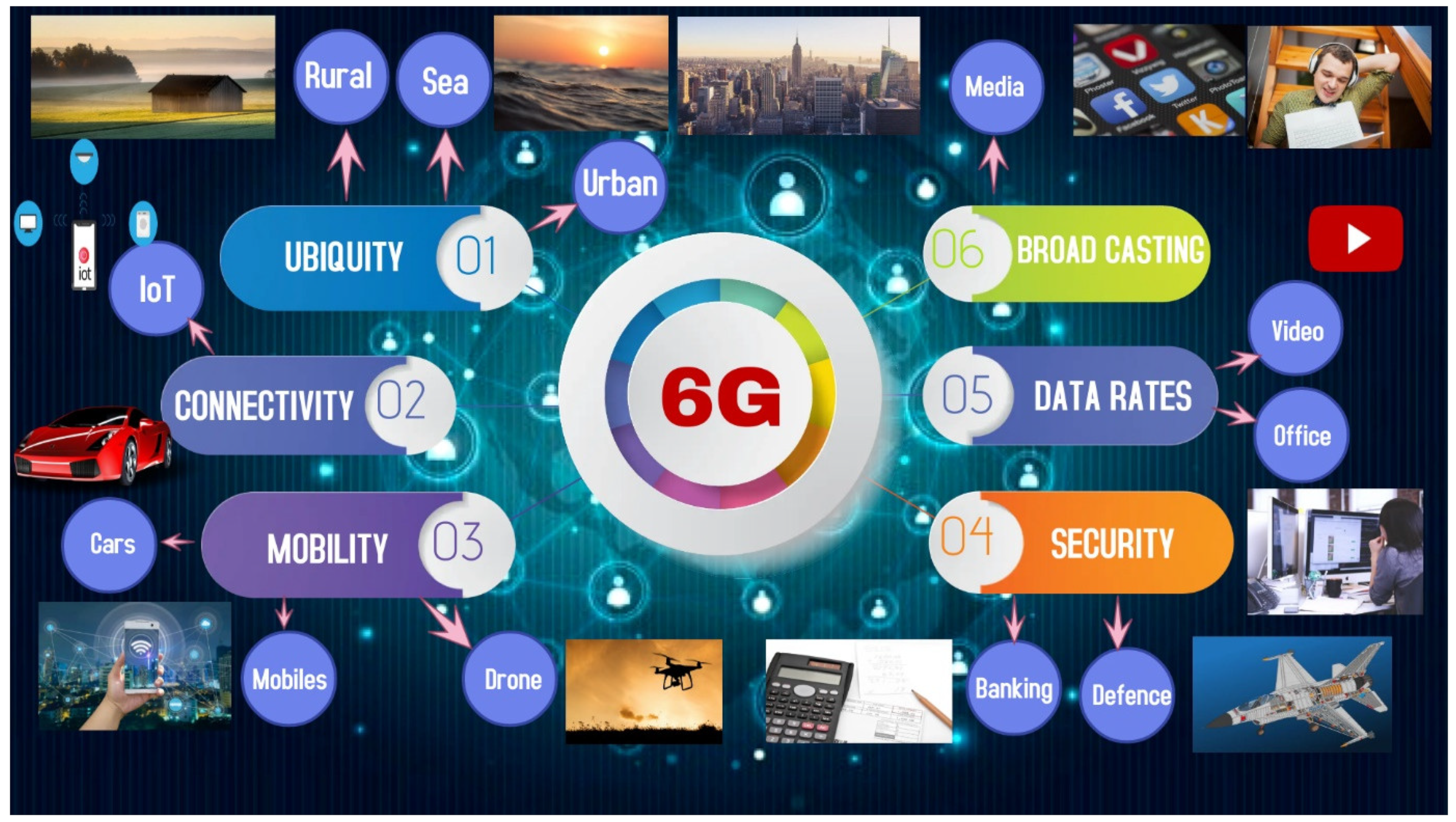
  • Connectivity: One of the key features of the transition from 5G to 6G is massive connectivity. A massive number of IoTs are expected to be connected with each other either in line of sight or non-line of sight scenarios. Uninterrupted connectivity will be achieved using artificial-intelligent-assisted reconfigurable meta-surfaces. Connectivity in large areas is expected to be achieved using integrated satellite and 5G networks.
  • Mobility: Intelligent transport systems with very high speed are expected. Ultra-low latency in data communication will improve the transportation system. The peak speed that is considered in 6G is 1000 Km/h for airline communication scenarios, which is much higher than 5G [31].
  • Security: Data privacy and security are essential aspects of any communication system, especially in the defense and banking sectors, as shown in Figure 3. By applying deep learning and artificial intelligence technologies in physical and network layers, the security will be improved in deceives, infrastructures, and assets in 6G networks.
  • Broadcasting: New multimedia services and infrastructures with the focus on ultra-high video streaming, live broadcasting, and entertainment will be available in 6G. That excellent quality of service will be achieved by a mixture of satellites, cables, and mobile technologies.
  • Ubiquity: The coverage area is expected to be larger compared to 5G systems. The 6G systems will include space and maritime communication along with ground-based communication to achieve large coverage and higher data rates. It will be available using a combination of GEO/LEO satellite and terrestrial networks. This is very important, especially for communication in aeroplanes, ships, and people living/working in remote areas.
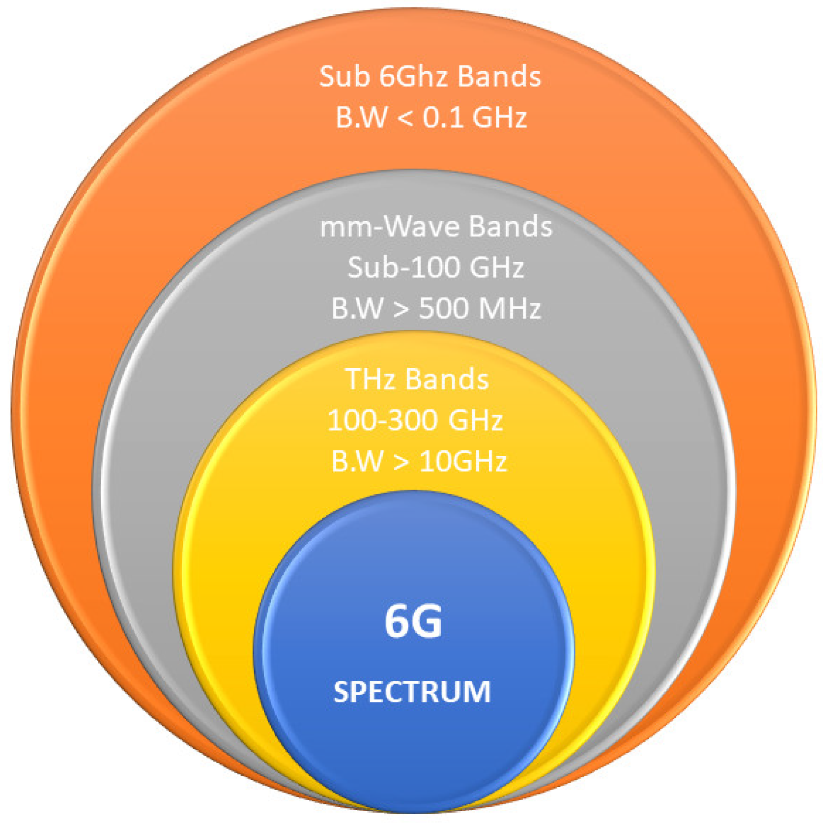
  • Data Rates: According to Shannon’s equation, the data rates directly proportional to capacity can be improved by enhancing bandwidth and the number of antennas. The mm-wave/THz bands provide significantly high bandwidth from 1 to 10 GHz. Hence, both techniques, a massive number of antennas and a Mm-wave/THz band, are direct methods to achieve a higher demand of data rates. It is expected to achieve 1 Tbps, which is higher than 5G in both up and downlinks [6,31]. The higher data rates are significant in almost all sectors, including ultra-high-definition video streaming, large data files in offices, etc.

2.2. The 6G Frequency Spectrums

In the transition to the 5G communication system, the 3G/4G/WiFi communication systems still exist. Thus, communication at sub-6 GHz will continue to function and will be part of 6G communication. The recent 5G communication, especially in mobile communication, has already been started and operates at sub-6 GHz bands. The sub-6 GHz bands for 5G are different in different countries, i.e., at 3100–3550 and 3700–4200 MHz in the United States, 3400–3800 MHz in Europe, 3300–3600 and 4800–5000 MHz in China and 3500 MHz in South Korea [32]. Broad bandwidth is expected at a higher frequency, which ultimately increases the data rates. Therefore, mm-wave bands from 30 to 100 GHz along with THz frequency bands from 100 GHz to 300 GHz are expected to be used in 6G communication [6]. Hence, the 6G communication system will be a combination of sub-6 GHz (BW < 0.1 GHz), mm-wave bands (BW > 0.5 GHz), and THz bands (BW > 10 GHz). The chart is also shown in Figure 4, showing expected frequency spectrums for 6G communication with their related bandwidth.

3. 5G Antennas, Arrays, and Wearable Devices

In order to design an effective antenna for a 5G handheld and mobile phone devices, several fundamental challenges need to be considered, especially at the mm-wave range. Two of those challenges are the free space loss (FSL) and atmospheric absorption (AA) that have high values due to the higher frequency of millimeter ranges [15]. Furthermore, FSL and AA allow for the reuse of the spectrum due to the limit of interference amount between adjacent cells. Although relatively lower losses and ease of technology can be achieved at lower microwave frequencies, these frequencies suffer from a lower data rate, high latency, and vice versa for the mm-wave range.
In addition, the 5G mm-wave antenna in wearable devices becomes even more challenging because the manufacturing process and tolerances at higher frequencies significantly affect its performance. Several aspects need to be taken into account when designing a wearable antenna for 5G applications for the utilization as an integrable part of worn devices. The details are given in the following sections.

3.1. Antennas for 5G Handheld Devices

As discussed in the introduction, the spectrum of the mobile communications systems below 3 GHz bands has been occupied through the last decade. This spectrum range suffers from high shortages and cannot keep up with the fast growth in the communications systems rate for the near future. A necessary solution for 5G wireless communication is the use of mm-wave bands to enhance communication quality [7,8,9,10,11,12,13,14,15,16]. However, communication systems at microwave frequencies still exist and will be part of future communication.
For the microwave range, small footprint, low cost, and stable radiation patterns are the main requirements, while at the mm-wave range, an antenna with wideband, stable radiation features and high gain (directive beam preferred) is desired to overcome high propagation loss at that frequency. The reported antennas in the literature can be classified according to two approaches: beam coverage concept and operational frequency concept. The 5G antennas are studied according to the beam coverage concept in the following parts.

3.1.1. 5G Antennas according to Operational Approach

Beam Steerable Antenna

The phased array antennas have significant challenges to implement inside the mobile handset because of size limitations [33]; the phased array is integrated with a phase shifter and digital beamforming to provide the same functions as a steerable antenna. Furthermore, many studies are introduced to solve this issue, which includes using patch [13], slot [34] and dipole antenna arrays [35]. These methods mainly use one-dimensional linear arrays, with a fan-shaped beam pattern, on separate substrates, positioned in the cellular handset to achieve a broad beam coverage and high gain within the restricted mobile size [36,37,38,39,40,41].
Bang et al. [7] introduced a dual-mode scenario of the proposed antenna arrays for the talking and data modes, as shown in Figure 5 and Figure 6. These two modes are introduced for beam-steering to provide high gain and wide coverage. The suggested antenna by the authors consists of two subarrays, each array with eight rotated slot antenna elements. The antenna is printed on the top of the upper frame and the handset’s back cover portion. According to the operating mode, the subarray is selected. The first subarray is positioned on the handset’s back cover to reduce the effect of the antenna on the user’s head and is operated when the handset is in talking mode. In contrast, the second antenna is placed on the front frame of the handset to operate in the browsing mode or data mode because the browsing mode needs a radiation pattern such as the hemispherical; this antenna is designed to operate at 28 GHz. In contrast, Zangh et al. [42] provided an antenna array consisting of two passive parasitic elements and one active element. Two switches are utilized in this design to control the steering beam. Two short circuit microstrip transmission lines with different lengths are connected with the switches. Two antenna arrays are printed on the sidewall of the mobile chassis to provide a 180° coverage angle. However, this antenna provides a good coverage angle with each state of switches but suffers from high complexity, 3D structures, and high loss in switches.

B. Switchable Phased Array

The phased array covers only 360°, so the switchable phased array is introduced to cover all angles using more than one antenna. Figure 7 shows the different radiation pattern shapes that can be used for 4G and 5G mobile phones. According to the shape of the radiation pattern and to cover all angles, at least three antennas will be needed for a 5G portable handset. Ojaroudiparchin et al. [13] introduced three printed antenna arrays in the mobile substrate’s three different sides, as shown in Figure 8. Each sub-array consists of eight rectangular patch antennas with a half-wavelength distance between the patches elements and fed by coaxial probes. This antenna operates from 21 to 22 GHz. To obtain the desired direction for the beam, the feed switches between the three sub-arrays. To select one from the three sub-arrays, a microwave switch kit is used to connect the feeding source to a power divider that connects to the phase shifter kit before each array.

Dual Polarized Antenna

Mastering the dual-polarized antennas to introduce a solution for enhancing the isolation and channel capacity makes these antennas a good candidate for MIMO smartphone designs [9,14,32,43,44,45,46,47,48]. In [49], Li et al., presented a dual-polarized antenna with eight elements for 5G smartphones, consisting of four C-shaped coupled fed elements and four L-shaped monopole slot elements to operate at sub-6 GHz. On a thick 1 mm FR-4 substrate, the four C-shaped elements are printed in the middle, while the four L-shaped elements are printed at the corners. Levels of 12.5 and 15 dB are achieved as the isolation and the cross-polarization, respectively. Zaho et al. [33] introduced an antenna for 5G/WLAN based on the integration between a cross bow-tie antenna and inverted cone monopole antenna for horizontal and vertical polarization. A separate power divider and phase shifter are created to be utilized as a feeding network where a 90° phase difference feeding network feeds the cross bow-tie antenna. In [50], Huang et al. proposed a dual-polarised antenna consisting of the main radiator, an annulus, and a reflector. The main radiator transmits energy to the coplanar patch through two pairs of differentially driven feedlines. For isolation and cross-polarization, this structure achieves 26 and 35 dB, respectively. In [51], an eight-port dual-polarized antenna array is reported, which is made up of four square loops, each of which is driven by two connected orthogonal feeding strips. Parchin et al. [14] employed a 4 square slot ring antenna to achieve dual-polarization, as shown in Figure 9. Each square ring slot is fed by two microstrip lines to achieve dual-polarization. The antennas are positioned at the four corners of the PCB to provide full coverage with dual-polarization. Two rings are printed with each antenna and operate as parasitic elements to provide isolation between the two ports of the antenna.
In [30], to fulfill the demands of 5G devices, a low-profile dual-polarized MIMO antenna with good isolation was developed. For a 28 GHz dual-polarized smartphone antenna, the integration of a vertically polarized slot and a horizontally polarized slot is applied. To achieve high gain, the antenna is paired with a meta-surface (MTS). The two-slot antennas feed the MTS. Two small slots are etched from the MTS and aligned with the antenna’s slots to increase the coupling between the antenna and the MTS. The proposed antenna’s arrangement with the MTS layer is depicted in Figure 10. With a dielectric constant of 3.38 and a thickness of 0.2 mm, the suggested antenna is printed on Rogers 4003C. The performance of MTS at 28 GHz is investigated using characteristic mode analysis. The antenna achieves high isolation coefficients of greater than 40 dB and cross-polarization of less than −40 dB based on simulated and actual data.
Table 2 presents a comparison between the proposed antenna and the referenced dual-polarized antennas, while Table 3 compares between MIMO antennas of smartphones. It is easy to note that the multi-layers and complex feeding structure are the two main aspects for achieving dual-polarization in [52,53,54,55,56]. Although the antenna in [48] is designed on a single layer, it has a highly complex feeding network to achieve dual-polarization. Compared to the other works, the dual-slot antenna in [30] features the benefits of high gain and wide bandwidth, high isolation, high cross-polarization, low profile, and compatibility with dual-polarization for 5G applications. On the other hand, the eight-element MIMO antennas for smartphones are reported in [32,55,56,57], but all those antennas have thick height except the antenna in [57] that has a thickness of 0.8 mm. The study of the antenna effect on the human body is not introduced in the aforementioned MIMO antennas. Furthermore, these papers achieve low efficiency and low isolation between its ports except the antenna that is introduced in [58], which achieves high efficiency (90%) and accepts isolation between its ports (20 dB). Otherwise, the antenna in [30] achieves high isolation between its ports, high gain, high efficiency, and very thin thickness compared to all antennas as mentioned above. The proposed work introduces a comprehensive study for all environments of smartphones and their effect on antenna performance and vice versa.

3.1.2. 5G Antennas according to the Operational Frequency Band

This part discusses 5G antennas based on the operating frequency, which includes sub-6 GHz band antennas, mm-wave band antennas, and dual-band antennas at sub-6 GHz and mm-wave band.

Sub-6 GHz 5G Antennas

Most of the reported antennas for lower 5G bands either integrate with previous 2G/3G/4G bands or work only for 5G sub-6 GHz, and they need a large radiator to resonate at the lower frequency bands mostly using a monopole antenna. During the last few years, some substantial studies have been carried out to address the requirements of 5G antennas only [30,61,62,63,64,65,66,67,68] or 4G/5G antennas [69,70,71,72,73,74,75,76,77,78]. The antennas in [61,62,63,64] are introduced to serve only the lower bands of 5G (sub-6-GHz) as shown in Figure 11a–c and Figure 12a–d. Such types of antennas that only serve lower 5G bands [61,69] are similar to those existing for previous mobile generations such as monopole [79,80,81], meander [82,83,84,85], open slot [86], slotted ground [87], PIFA [88], and loop [89].

mm-Wave Antennas

For the upper band of 5G, different antennas configurations are reported in the literature [30,65,66,90,91,92]. In [93], a dual-polarized frame integrated antenna is introduced to serve in the mobile handset at the mm-wave range. The antenna is shown in Figure 13, which has dual-polarized cavity-backed bow-tie slot arrays integrated on the frame of the mobile handset. Each array consists of a 4-bow-tie slot unit, which operates at 27.3–28.2 GHz and achieves a gain of 12.8 dBi. The orthogonal orientation of the antennas successfully reduces the mutual coupling between the adjacent element to be 13 dB. In comparison, Paola et al. [65] used the concept of the planar Yagi-uda antennas, which are printed on a small portion of the mobile PCB, as shown in Figure 14. Five antennas are printed on the shortage edge of the board and pointing in different directions to achieve wide beam steering. This antenna achieves a wide impedance bandwidth from 26 to 40 GHz with a maximum gain of 8 dBi.

Sub 6 GHz and mm-Wave Antennas

A connected slot antenna array (CSAA) is introduced in [10,73,92,94,95,96,97] to operate at microwave bands and mm-wave bands. In the CSAA, the small length slots are connected in series to offer a large slot for microwave range. The distance between successive feeders is the main parameter to control the resonant frequency equal to the half-guided wavelength. Figure 15 illustrates the CSAA configuration, consisting of eight feeders for mm-wave and a single feeder for lower frequency. In order to enhance the inherent property of the narrow bandwidth of a slot antenna at a lower frequency, a tuning varactor is applied.
The hybrid approach is another solution to achieve dual bands; each band is achieved by different radiators in such antennas, but the main challenge is the size limitation. In order to reduce the size of the antenna, Ikram et al. [74] as shown in Figure 16 introduced a compact size antenna based on a ground slot to integrate lower and upper bands of 5G by exciting different radiating modes. The mm-wave antenna is embedded inside the footprint of the microwave antenna to compromise the antenna structure. The large rectangular slot is utilized to operate at 0.8 and 2 GHz by exciting two different modes. At the same time, the mm-wave band is covered using four Vivaldi elements that are connected in a parallel configuration to achieve a high directive pattern at 28 GHz. The concept of MIMO is applied to achieve diversity of radiation patterns. The full configuration is shown in Figure 16.
On the other hand, a triple-band antenna is reported in [98] for dual-band operation in the mm-wave frequencies (28 and 38 GHz); the suggested antenna consists of a microstrip patch radiator with an inverted U-shaped slot. A compact microstrip resonant cell (CMRC) low pass filter (LPF) connects a meandering radiating structure to a microstrip patch radiator, allowing these structures to be integrated and operate at 3.5 GHz. By adding the radiator slot, an LPF, the truncated ground, and a meandering line structure, the suggested antenna achieves a compact dimension of 22 by 10 by 0.508 mm as shown in Figure 17. The proposed MIMO antenna demonstrates wide impedance bandwidth (at −10 dB) of 12.9%, 5.8%, and 2.4% at 3.5, 28, and 38 GHz, respectively, without using an external decoupling structure.

3.2. Antennas for 5G Access Points

Zhang et al. [99] utilized a cavity-backed slot antenna (CBSA) integrated with a bandpass frequency selective service (FSS) to operate at around 25 GHz, see Figure 18a,b. The FSS is reused as radiator patches at the lower frequency band to cover the lower 5G band at 2.6 GHz. The whole structure consists of 4 × 4 CBSA and covers a band from 23.4 to 26.1 GHz, and the FSS is used to enhance the antenna performance and increase the gain to be about 15 dBi on average along with covering the lower band from 2.48 to 2.66 GHz with a gain of 8 dBi as shown in Figure 18c,d.
While in [97], the concept of shared aperture cavity slot antenna based on thick patch is reported, a large cavity is designed to operate at the lower frequency (S-band) with large dimensions. It is divided into 16 small cavities served at the Ka-band. Eight of these Ka-band antenna elements emit a + 45 ° slanted polarisation (SP) wave, while the other half emits a 45 ° SP wave. Coaxial cables feed these units, which are organized in a checkerboard pattern. The S-band feeding structure is a microstrip-fed slot that runs the thick patches in S-band as a T M 010 mode. The antenna demonstrates good performance in terms of impedance bandwidth over the S-band (3.44–3.56 GHz) and the Ka-band (27.54–28.46 GHz); the measurement findings reveal realized gains of 4.06–5.35 and 12.0–14.5 dBi, respectively, see Figure 19. Table 4 summarizes the features of the aforementioned antennas and others reported in the literature to make it easy for the readers to compare between them in terms of operating frequency (lower and upper band), MIMO implementation, number of ports, isolation, gain and board size.

3.3. Antennas at THz Frequency Bands

As discussed before, THz frequency bands from 100 to 300 GHz are considered for 6G communication. Antenna design complexity increases at such higher frequencies, which in return creates more challenges in terms of material selection, design process, fabrication techniques, and experimental validations. Hence, this section presents an overview of recently published 6G antenna designs.
Some antenna types in the recent existing literature have been considered for 6G THz bands [106,107,108,109]. In [106], a conical horn antenna is presented at a 300 GHz band. The horn antenna provides directive high gain radiation patterns, which are desirable at 300 GHz, with a very large bandwidth from 270 to 330 GHz. This is an extraordinary performance satisfying the 6G requirements. The antenna is realized using the electrical discharge machining technique. Another antenna design is presented in [107] at the 60 GHz band. A printed circuit board technology was used to develop an antenna in a package. Antenna in a package technology is low cost and very useful for high-frequency applications. The whole antenna design with its design evolution steps is shown in Figure 20. Another low-profile fully metallic antenna with a high gain performance at 292 GHz is published in [108]. The antenna provides a 5 GHz bandwidth from 292 to 297 GHz. The antenna fabrication process is realized by laser technology. On the other hand, a dielectric waveguide is used for different techniques to achieve high gain, directive, compact size, and high-efficiency antennas in the sub-THz range [110,111] and CMOS technologies [112,113].

3.4. 5G Wearable Antennas

The demand for wearable devices has grown tremendously in the last decade. The number of connected wearable electronic devices has increased by more than 100% in the last 4 years, rising from 325 million in 2016 to about 720 million in the year 2019 [114,115,116,117,118]. As technology continues growing at a high rate, these devices are expected to reach 1.1 billion by 2022 [116]. A wearable antenna is one of the essential elements of the wearable electronics that are utilized for several wearable applications ranging from medical to military to entertainment and other daily-use wearable devices [117], as can be seen in Figure 21. A few examples that include wearable antennas are medical devices and monitoring patient health, smartwatches with incorporated small antennas, military tracking and navigation systems, body-worn camera with WiFi and Bluetooth, and wearable athletic devices, etc. [119,120,121,122,123,124]. Nevertheless, the design of the wearable antenna is critical, particularly for 5G mm-Wave and IoT applications in which the manufacturing process and tolerances at higher frequencies have a huge effect on its performance. There are also several aspects that need to be taken into account when designing a wearable antenna for 5G applications for the utilization as an integrable part of worn devices [117]. They need to be conformal/flexible, robust, and operate with minimum performance degradation in close vicinity with the human body. It is well-known that the human body tends to degrade antenna efficiency and gain due to the natural losses of the body tissues, and thus the implementation environment needs to be considered during the design process to achieve a highly stable and robust 5G wearable antenna [125]. The wearable antenna should also effectively operate under different bending conditions as part of the important requirements for such devices. On the other hand, the utilized materials as substrates and conductive parts for the wearable antennas are very important [126]. They must be chosen carefully to provide the required mechanical/physical features such as bending, wrapping, and sometimes washing while maintaining minimal influence on the performance [127].
In the following subsections, we go through the state-of-the-art of 5G wearable antennas, which includes a summary of the presented structures, techniques, materials substrates, and performances. In fact, there are a plethora of different kinds of wearable antennas that have been utilized for numerous wearable electronic devices, as can be found in the literature [125,128,129,130,131]. However, these antennas are mainly proposed for 4G, 3G, and older technologies. The recent progress on wearable antennas for 5G applications is limited to a few works. This is due to the fact that the 5G and future 6G technologies are still recent and the classical optimization methods of wearable antennas are not always suitable to achieve the requirements of these advanced technologies.

3.4.1. Sub-6 GHz 5G Wearable Antennas

A conventional modified microstrip patch antenna is designed on a thin (0.125 mm) layer of polyethylene terephthalate (PET) substrate for 5G applications [132]. The conductive part of the antenna was made of silver nanoparticles using inkjet printer technology. The overall dimensions of the reported antenna are 60 × 75 mm2, and the final fabricated prototype is shown in Figure 22. The antenna operates at around 5 GHz and over the X-band region and demonstrated a maximum gain of 5dBi and about 38% radiation efficiency. The utilized polymer substrate and silver nanoparticles conductive ink technologies with the presented antenna in [132] is of great interest for wearable antennas as it is compatible for wearing and has sufficient flexibility, efficiency, and robustness. However, the antenna dimensions are quite large for integration with compact wearable devices, and further optimization techniques to miniaturize the overall size of the antenna are demanded.
A conformal dielectric resonator wristwatch-like wearable antenna for sub-6 GHz 5G and IoT applications is described in [133]. The 3D structure of the dielectric resonator antenna allows the excitation of various operating modes in one antenna and thus makes it feasible to suit different applications. The other advantages of the dielectric resonator techniques are also the operating wideband and high gain and efficiency characteristics. However, the 3D structure and commonly high-profile features of this type of antenna are not favorable for flexible/wearable antennas. A modified coplanar feeding technique has been utilized in [133] to provide good isolation between the radiating aperture and the platform. The isolation is achieved by a metal plane that acts as a barrier and hence minimizes the unfavorable interferences from the platform and users. It can be noticed that the presented conformal dielectric resonator antenna demonstrated a significant alteration in its performance, including radiation patterns and realized gain, under different bending angles and when it was placed on different parts of the body. These results explain the less existing conformal dielectric resonator antennas for wearable applications in the literature.
In [134], a multiband textile-based rectangular microstrip patch antenna for sub-6 GHz 5G communication application is presented. The antenna is employed with annular and U-Shaped slots etched on the center and edge of the patch, respectively, to achieve the multiband operating frequencies at 0.85, 2.2, and 3.5 GHz. The desired surface current distributions and bandwidth enhancement are obtained by utilizing a meandering ground plane on the rear side of the antenna. While the work did not include measured results for verification, the utilized algorithm of the Coral Reef’s optimization technique has demonstrated promising numerical results, which encourage the antenna designers to use such algorithms and artificial intelligence (AI) [135] optimization techniques to tune and optimize 5G wearable antennas for obtaining an efficient and high-performance wearable antenna.
A conductive graphene-based conformal and low-profile dual-band Vivaldi antenna is reported in [136] for 5G WiFi applications. The antenna configuration is shown in Figure 23a,b, which comprises an open circuit half-wave and split-ring-resonator to obtain the dual-band operating frequencies at 2.4–2.45 and 5.51–7 GHz. The antenna achieved a maximum measured gain of 6.8 dBi, as can be seen in Figure 23c. As mentioned earlier, the important features of the wearable antenna are the stable performance with minimum degradation of operating frequency and radiation patterns when the antenna is bent or twisted. This antenna demonstrated a similar operating frequency with minimal shift and stable radiation patterns under different bending conditions, as can be seen from the measured results in Figure 23d,e.
A transparent polymer-based and compact multiple-input multiple-output (MIMO) antenna is presented in [137] for 5G smart wearable and remote devices. The antenna has utilized new promising nanotechnology of Nickel metallic mesh as a conductor. The antenna featured a compact size with a transparent look, high conductivity of nano-nickel metallic mesh, and high mechanical stability. The antenna has achieved 93% efficiency and below −20 dB isolation over the operating frequency band of 4.4–5 GHz. The utilization of such new flexible conductive materials at nanoscale particles and flexible transparent dielectrics are encouraging and could lead to highly efficient wearable smart antennas for next-generation technologies. There are a few other antennas that are based on transparent polymer substrates that were reported in [138,139,140].

3.4.2. mm-Wave 5G Wearable Antennas

The limitation of the spectrum at the lower microwave frequencies calls for the utilization of the available spectrum at higher mm-wave frequencies for 5G technology, including 5G wearable antennas [117]. Nevertheless, the utilization of such high frequencies will result in greater propagation losses. Therefore, 5G wearable antennas are required to be highly directive with higher gain to minimize this issue and to ensure the mm-wave wearable antennas have the required operating competence. In this subsection, an overview of exiting mm-wave 5G wearable antennas is presented.
An early work on mm-wave antenna for off-body 5G application is described in [141]. The 60-GHz mm-wave band was selected to investigate the electromagnetic exposure of body-mounted antennas and their effect on the human body. The work includes the analysis of antenna array with three different feeding structures on the human body and compared their performances and user exposure. It concluded that the presence of a metal ground plane reduced the electromagnetic exposure by 70 and 8 times in terms of peak and averaged levels. It also helps to reduce the sensitivity of the reflection coefficient when the antenna is mounted on a human body. Though this investigation utilized a conventional rigid antenna, it has emphasized several important factors that need to be considered when designing a highly sensitive mm-wave wearable antenna. These include safety aspects and limitations of some traditional techniques due to the higher sensitivity of the mm-wave antennas to the human body. A flexible reconfigurable MIMO mm-wave wearable antenna that can be controlled to operate at selected frequencies between 26.5–40 GHz is introduced in [142]. The presented antenna is comprised of a T-shape radiating element fixed in a rectangular cut aperture on the ground plane, as can be seen in Figure 24a–c. The radiating element is incorporated with two slots on each side and electronic switches. The antenna was manufactured using inkjet printing technology on a thin flexible polyethylene-terephthalate film. The free-space measured results of the described mm-wave MIMO antenna showed a stable reflection coefficient and a radiation pattern with peak gain of 6.2 dBi and isolation below −20 dB between the two elements. Despite the stable performance on the free-space environment, the performance of the antenna was not tested in close vicinity of a human body to verify the antenna performance stability for actual implementation.
S. Jilani et al. [143] introduced a wideband mm-wave liquid crystal polymer-based flexible antenna array for 5G wireless network application. The antenna comprised two-element arrays of rectangular side-tapered patches fed using coplanar-waveguide-fed (CPW) and corporate transmission line techniques. To achieve appropriate coupling and attain good impedance matching, two additional small stubs were introduced on the CP. The antenna was manufactured using an advanced method of laser-milling and inkjet printing technologies on a thin flexible polymer film. The measurement result of reflection coefficients shows that the antenna exhibits a wideband over 26–40 GHz with a maximum gain of 11 dBi at 35 GHz. However, there are no verifications on the performance of the antenna in close vicinity with the human body. A similar fabrication inkjet printing technology is utilized with a conventional structure dipole array antenna for emerging 5G medical applications and is described in [144]. The reported antenna operates at 23–30 GHz. Though there was obvious variation between simulated and measured results due to the fabrication tolerances as mentioned by the authors, the performance of the antenna in terms of gain, radiation patterns and reflection coefficient is satisfactory. Further investigation and analysis of the safety aspect and bending and twisting when the antenna is close to the human body is required.
EL Wissem et al. [145] reported a conformal mm-wave textile-based antenna operating at 26 GHz for 5G cellular applications. The antenna was incorporated with an electromagnetic bandgap (EBG) structure that was placed around the patch. The EBG has improved the gain and efficiency of the antenna by 2.5 dB and 7% compared to without EBG. The EBG structure also reduced the specific absorption rate (SAR) by 70% to within the acceptable safe level exposure.
A circularly polarized mm-wave wearable antenna for 5G wearable application is introduced by Ubaid et al. [146] (see Figure 25). The antenna was based on a straight microstrip transmission line printed on one side, and the EM energy is coupled to a square patch on the other side through a V-shape slot aperture. The circular polarization feature is achieved by parallel alignment of the patch edges to each arm of the V-shape slots with orthogonal arms. This configuration results in a compact size antenna with a wideband and high gain CP antenna operating at the frequency band of 27.2–30.5 GHz. The antenna also achieved a stable 3-dB axial ratio bandwidth over 27.3–29.7 with a maximum gain of 11 dBi and 90% efficiency. The antenna also attained stable and directional electromagnetic radiations. Despite the compact topology and good performance, this work is missing an SAR analysis to evaluate the energy exposure for safety purposes.
More recently, a textile-based mm-wave wearable antenna was introduced in [147]. The antenna operates at higher-order mode covering the frequency band of 24.9–31 GHz. The antenna demonstrated a measured gain of 8.2 dBi. An array of 13 × 13 elements was also evaluated to explore the efficacy of receiving power, and the numerical results illustrated the potential for up to six times higher power reception compared to a conventional patch. Overall, the existing wearable antennas for 5G applications that are described in this review show the advancements and efforts that were put forward by researchers in this field to address most of the challenges of wearable antennas for the emerging technologies of the 5G and 6G eras.

4. Conclusions

In this article, the potential 6G communication system and its key features have been summarized. It has been presented that the next generations (5G/B5G/6G) of communication systems and wearable technologies will aim to achieve high data rates, ultra-high security, low-energy consumption, broadband internet everywhere, and massive connections of IoT. Since those systems will be a mixture of many services employing many frequency spectrums (Sub- 6 GHz, mm-wave, and THz), it is challenging to accommodate a greater number of antennas into a single device. Thus, the current state-of-the-art 5G antennas and arrays are summarized to show a way forward to upcoming communication systems. At the end of the article, the key features and requirements of the wearable antennas for next-generation technology were also presented.

Author Contributions

Conceptualization, M.I.; methodology, M.I. and A.S.M.A.; writing—original draft preparation, M.I. and A.S.M.A.; writing—review and editing, M.I., M.F.L., K.S. and A.S.M.A.; visualization, M.I. and M.F.L. All authors have read and agreed to the published version of the manuscript.

Funding

This research received no external funding.

Institutional Review Board Statement

Not applicable.

Informed Consent Statement

Not applicable.

Data Availability Statement

Not applicable.

Acknowledgments

This work was undertaken during post-doctoral research fellowships at the School of ITEE, the University of Queensland, Australia.

Conflicts of Interest

The authors declare no conflict of interest.

References

  1. Giordani, M.; Polese, M.; Mezzavilla, M.; Rangan, S.; Zorzi, M. Toward 6G Networks: Use Cases and Technologies. IEEE Commun. Mag. 2020, 58, 55–61. [Google Scholar] [CrossRef]
  2. Gui, G.; Liu, M.; Tang, F.; Kato, N.; Adachi, F. 6G: Opening new horizons for integration of comfort, security, and intelligence. IEEE Wirel. Commun. 2020, 27, 126–132. [Google Scholar] [CrossRef]
  3. Ikram, M. Multi-Functional Antenna Structures for 4G/5G Wireless Communication Devices. Ph.D. Thesis, The University of Queensland, Brisbane, Australia, 2021. [Google Scholar]
  4. Hong, W. Solving the 5G Mobile Antenna Puzzle: Assessing Future Directions for the 5G Mobile Antenna Paradigm Shift. IEEE Microw. Mag. 2017, 18, 86–102. [Google Scholar] [CrossRef]
  5. Jornet, J.M.; Akyildiz, I.F. Channel Modeling and Capacity Analysis for Electromagnetic Wireless Nanonetworks in the Terahertz Band. IEEE Trans. Wirel. Commun. 2011, 10, 3211–3221. [Google Scholar] [CrossRef] [Green Version]
  6. Rajatheva, N.; Atzeni, I.; Bjornson, E.; Bourdoux, A.; Buzzi, S.; Dore, J.B.; Erkucuk, S.; Fuentes, M.; Guan, K.; Hu, Y.; et al. White paper on broadband connectivity in 6G. arXiv 2020, arXiv:2004.14247. [Google Scholar]
  7. Bang, J.; Choi, J. A SAR Reduced mm-Wave Beam-Steerable Array Antenna With Dual-Mode Operation for Fully Metal-Covered 5G Cellular Handsets. IEEE Antennas Wirel. Propag. Lett. 2018, 17, 1118–1122. [Google Scholar] [CrossRef]
  8. Buey, C. Design and Measurement of Multi-Antenna Systems toward Future 5G Technologies. Ph.D. Thesis, Université Côte d’Azur, Nice, France, 2018. [Google Scholar]
  9. Deckmyn, T.; Cauwe, M.; Ginste, D.V.; Rogier, H.; Agneessens, S. Dual-band (28,38) GHz coupled quarter-mode sub-strate-integrated waveguide antenna array for next-generation wireless systems. IEEE Trans. Antennas Propag. 2019, 67, 2405–2412. [Google Scholar] [CrossRef] [Green Version]
  10. Ikram, M.; Hussain, R.; Sharawi, M.S. 4G/5G antenna system with dual function planar connected array. IET Microw. Antennas Propag. 2017, 11, 1760–1764. [Google Scholar] [CrossRef]
  11. Krishna, S. Design and Development of 5G Spectrum Massive MIMO Array Antennas for Base Station and Access Point Applications. Ph.D. Thesis, San Diego State University, San Diego, CA, USA, 2018. [Google Scholar]
  12. Løvaas, H.G.D. Multiband UWB Antenna Design for WiFi, LTE and 5G. Master’s Thesis, The Norwegian University of Science and Technology, Trondheim, Norway, 2017. [Google Scholar]
  13. Ojaroudiparchin, N.; Shen, M.; Zhang, S.; Pedersen, G.F. A Switchable 3-D-Coverage-Phased Array Antenna Package for 5G Mobile Terminals. IEEE Antennas Wirel. Propag. Lett. 2016, 15, 1747–1750. [Google Scholar] [CrossRef] [Green Version]
  14. Parchin, N.O.; Al-Yasir, Y.; Ali, A.H.; Elfergani, I.; Noras, J.M.; Rodriguez, J.; Abd-Alhameed, R.A. Eight-Element Dual-Polarized MIMO Slot Antenna System for 5G Smartphone Applications. IEEE Access 2019, 7, 15612–15622. [Google Scholar] [CrossRef]
  15. Salous, S.; Degli Esposti, V.; Fuschini, F.; Thomae, R.S.; Mueller, R.; Dupleich, D.; Haneda, K.; Garcia-Pardo, J.M.M.; Garcia, J.P.; Gaillot, D.P.; et al. Millimeter-wave propagation: Characterization and modeling toward fifth-generation systems. IEEE Antennas Propag. Mag. 2016, 58, 115–127. [Google Scholar] [CrossRef] [Green Version]
  16. Zhao, A.; Ren, Z. Size Reduction of Self-Isolated MIMO Antenna System for 5G Mobile Phone Applications. IEEE Antennas Wirel. Propag. Lett. 2018, 18, 152–156. [Google Scholar] [CrossRef]
  17. Chataut, R.; Akl, R. Massive MIMO systems for 5G and beyond networks—Overview, recent trends, challenges, and future research direction. Sensors 2020, 20, 2753. [Google Scholar] [CrossRef] [PubMed]
  18. You, L.; Li, K.X.; Wang, J.; Gao, X.; Xia, X.G.; Ottersten, B. Massive MIMO transmission for LEO satellite communications. IEEE J. Sel. Areas Commun. 2020, 38, 1851–1865. [Google Scholar] [CrossRef]
  19. Liu, P.; Li, Y.; Cheng, W.; Gao, X.; Zhang, W. Multi-Beam NOMA for Millimeter-Wave Massive MIMO with Lens Antenna Array. IEEE Trans. Veh. Technol. 2020, 69, 11570–11583. [Google Scholar] [CrossRef]
  20. Basenese, L. 5 Reasons to Let It Ride on 5G. Available online: https://www.smarteranalyst.com/bloggers-corner/resonant-resn-5-reasons-to-let-it-ride-on-5g/ (accessed on 1 March 2019).
  21. Björnson, E.; Sanguinetti, L.; Wymeersch, H.; Hoydis, J.; Marzetta, T.L. Massive MIMO is a reality—What is next?: Five promising research directions for antenna arrays. Digit. Signal Process. 2019, 94, 3–20. [Google Scholar] [CrossRef]
  22. Yon, H.; Rahman, N.H.A.; Aris, M.A.; Jamaluddin, M.H.; Lin, I.K.C.; Jumaat, H.; Redzwan, F.N.M.; Yamada, Y. Development of C-Shaped Parasitic MIMO Antennas for Mutual Coupling Reduction. Electronics 2021, 10, 2431. [Google Scholar] [CrossRef]
  23. Farasat, M.; Thalakotuna, D.N.; Hu, Z.; Yang, Y. A Review on 5G Sub-6 GHz Base Station Antenna Design Challenges. Electronics 2021, 10, 2000. [Google Scholar] [CrossRef]
  24. Hassan, A.K.; Moinuddin, M.; Al-Saggaf, U.M.; Aldayel, O.; Davidson, T.N.; Al-Naffouri, T.Y. Performance Analysis and Joint Statistical Beamformer Design for Multi-User MIMO Systems. IEEE Commun. Lett. 2020, 24, 2152–2156. [Google Scholar] [CrossRef]
  25. Hassan, A.K.; Moinuddin, M.; Al-Saggaf, U.M.; Al-Naffouri, T.Y. Performance Analysis of Beamforming in MU-MIMO Systems for Rayleigh Fading Channels. IEEE Access 2017, 5, 3709–3720. [Google Scholar] [CrossRef] [Green Version]
  26. Siddique, U.; Tabassum, H.; Hossain, E.; Kim, D.I. Wireless backhauling of 5G small cells: Challenges and solution approaches. IEEE Wirel. Commun. 2015, 22, 22–31. [Google Scholar] [CrossRef]
  27. Bariah, L.; Mohjazi, L.; Muhaidat, S.; Sofotasios, P.C.; Kurt, G.K.; Yanikomeroglu, H.; Dobre, O.A. A Prospective Look: Key Enabling Technologies, Applications and Open Research Topics in 6G Networks. IEEE Access 2020, 8, 174792–174820. [Google Scholar] [CrossRef]
  28. Giambene, G.; Kota, S.; Pillai, P. Satellite-5G Integration: A Network Perspective. IEEE Netw. 2018, 32, 25–31. [Google Scholar] [CrossRef]
  29. Schwarz, R.T.; Delamotte, T.; Storek, K.-U.; Knopp, A. MIMO Applications for Multibeam Satellites. IEEE Trans. Broadcast. 2019, 65, 664–681. [Google Scholar] [CrossRef] [Green Version]
  30. Sultan, K.S.; Abdullah, H.H.; Abdallah, E.A.; El-Hennawy, H.S. Metasurface-Based Dual Polarized MIMO Antenna for 5G Smartphones Using CMA. IEEE Access 2020, 8, 37250–37264. [Google Scholar] [CrossRef]
  31. Jiang, W.; Han, B.; Habibi, M.A.; Schotten, H.D. The Road Towards 6G: A Comprehensive Survey. IEEE Open J. Commun. Soc. 2021, 2, 334–366. [Google Scholar] [CrossRef]
  32. Li, A.; Luk, K.-M.; Li, Y. A Dual Linearly Polarized End-Fire Antenna Array for the 5G Applications. IEEE Access 2018, 6, 78276–78285. [Google Scholar] [CrossRef]
  33. Alhalabi, R.A.; Rebeiz, G.M. High-Efficiency Angled-Dipole Antennas for Millimeter-Wave Phased Array Applications. IEEE Trans. Antennas Propag. 2008, 56, 3136–3142. [Google Scholar] [CrossRef]
  34. Hussain, R.; Alreshaid, A.T.; Podilchak, S.K.; Sharawi, M.S. Compact 4G MIMO antenna integrated with a 5G array for current and future mobile handsets. IET Microw. Antennas Propag. 2017, 11, 271–279. [Google Scholar] [CrossRef] [Green Version]
  35. Ta, S.X.; Choo, H.; Park, I. Broadband Printed-Dipole Antenna and Its Arrays for 5G Applications. IEEE Antennas Wirel. Propag. Lett. 2017, 16, 2183–2186. [Google Scholar] [CrossRef]
  36. Ala-Laurinaho, J.; Aurinsalo, J.; Karttunen, A.; Kaunisto, M.; Lamminen, A.; Nurmiharju, J.; Raisanen, A.V.; Saily, J.; Wainio, P. 2D Beam-Steerable Integrated Lens Antenna System for 5G E-Band Access and Backhaul. IEEE Trans. Microw. Theory Tech. 2016, 64, 2244–2255. [Google Scholar] [CrossRef]
  37. Taheri, M.M.S.; Abdipour, A.; Zhang, S.; Pedersen, G.F. Integrated Millimeter-Wave Wideband End-Fire 5G Beam Steerable Array and Low-Frequency 4G LTE Antenna in Mobile Terminals. IEEE Trans. Veh. Technol. 2019, 68, 4042–4046. [Google Scholar] [CrossRef] [Green Version]
  38. Tanaka, H.; Ohira, T. Beam-steerable planar array antennas using varactor diodes for 60-GHz-band applications. In Proceedings of the 33rd European Microwave Conference Proceedings (IEEE Cat. No.03EX723C), Munich, Germany, 7 October 2003; Volume 3, pp. 1067–1070. [Google Scholar]
  39. Tanaka, H.; Ohira, T. A single-planar integrated self-heterodyne receiver with a built-in beam-steerable array antenna for 60-GHz-band video transmission systems. In Proceedings of the IEEE MTT-S International Microwave Symposium Digest (IEEE Cat. No.04CH37535), Fort Worth, TX, USA, 6–11 June 2004; Volume 2, pp. 735–738. [Google Scholar]
  40. Wu, P.; Chen, S. Design of beam-steerable dual-beam reflectarray. In Proceedings of the 2017 IEEE International Symposium on Antennas and Propagation & USNC/URSI National Radio Science Meeting, San Diego, CA, USA, 9–14 July 2017; pp. 2081–2082. [Google Scholar]
  41. Yazid, Y.; Xun, G. Beam-steerable patch antenna array using parasitic coupling and reactive loading. In Proceedings of the 2007 IEEE Antennas and Propagation Society International Symposium, Honolulu, HI, USA, 9–15 June 2007; pp. 4693–4696. [Google Scholar]
  42. Zhang, S.; Syrytsin, I.; Pedersen, G.F. Compact Beam-Steerable Antenna Array with Two Passive Parasitic Elements for 5G Mobile Terminals at 28 GHz. IEEE Trans. Antennas Propag. 2018, 66, 5193–5203. [Google Scholar] [CrossRef] [Green Version]
  43. Chen, Q.; Zhang, H. Dual-Patch Polarization Conversion Metasurface-Based Wideband Circular Polarization Slot Antenna. IEEE Access 2018, 6, 74772–74777. [Google Scholar] [CrossRef]
  44. Chu, H.-L. Investigations and Design of Wideband Dual Linear Polarized Massive MIMO Panel Array Antenna for 5G Communication Applications. Ph.D. Thesis, San Diego State University, San Diego, CA, USA, 2018. [Google Scholar]
  45. Hu, X.; Yan, S.; VandenBosch, G.A.E. Compact Circularly Polarized Wearable Button Antenna with Broadside Pattern for U-NII Worldwide Band Applications. IEEE Trans. Antennas Propag. 2018, 67, 1341–1345. [Google Scholar] [CrossRef]
  46. Li, A.; Luk, K. Millimeter-wave dual linearly polarized end-fire antenna fed by 180-degree hybrid coupler. IEEE Antennas Wirel. Propag. Lett. 2019, 18, 1390–1394. [Google Scholar] [CrossRef]
  47. Li, H.; Kang, L.; Wei, F.; Cai, Y.-M.; Yin, Y.-Z. A Low-Profile Dual-Polarized Microstrip Antenna Array for Dual-Mode OAM Applications. IEEE Antennas Wirel. Propag. Lett. 2017, 16, 3022–3025. [Google Scholar] [CrossRef]
  48. Wang, C.; Chen, Y.; Yang, S. Bandwidth Enhancement of a Dual-Polarized Slot Antenna Using Characteristic Modes. IEEE Antennas Wirel. Propag. Lett. 2018, 17, 988–992. [Google Scholar] [CrossRef]
  49. Li, M.Y.; Ban, Y.L.; Xu, Z.Q.; Wu, G.; Kang, K.; Yu, Z.F. Eight-port orthogonally dual-polarized antenna array for 5G smartphone applications. IEEE Trans. Antennas Propag. 2016, 64, 3820–3830. [Google Scholar] [CrossRef]
  50. Huang, H.; Li, X.; Liu, Y. A Low-Profile, Dual-Polarized Patch Antenna for 5G MIMO Application. IEEE Trans. Antennas Propag. 2018, 67, 1275–1279. [Google Scholar] [CrossRef]
  51. Li, M.; Xu, Z.; Ban, Y.; Sim, C.; Yu, Z. Eight-port orthogonally dual-polarised MIMO antennas using loop structures for 5G smartphone. IET Microw. Antennas Propag. 2017, 11, 1810–1816. [Google Scholar] [CrossRef]
  52. Wang, J.; Wang, W.; Liu, A.; Guo, M.; Wei, Z. Cross-Polarization Suppression of a Dual-Polarized Microstrip Antenna Using Enclosed Substrate-Integrated Cavities. IEEE Antennas Wirel. Propag. Lett. 2019, 19, 64–68. [Google Scholar] [CrossRef]
  53. Liu, D.; Gu, X.; Baks, C.W.; Valdes-Garcia, A. Antenna-in-package design considerations for Ka-band 5G communication ap-plications. IEEE Trans. Antennas Propag. 2017, 65, 6372–6379. [Google Scholar] [CrossRef]
  54. Wu, C.; Lu, C.; Cao, W. Wideband Dual Polarization Slot Antenna with High Isolation by Using Microstrip Line Balun Feed. IEEE Antennas Wirel. Propag. Lett. 2017, 16, 1759–1762. [Google Scholar] [CrossRef]
  55. Zhang, J.; Zhao, K.; Wang, L.; Zhang, S.; Pedersen, G.F. Dual-Polarized Phased Array with End-Fire Radiation for 5G Handset Applications. IEEE Trans. Antennas Propag. 2019, 68, 3277–3282. [Google Scholar] [CrossRef]
  56. Zhang, J.; Lin, X.Q.; Nie, L.Y.; Yu, J.W.; Fan, Y. Wideband Dual-Polarization Patch Antenna Array with Parallel Strip Line Balun Feeding. IEEE Antennas Wirel. Propag. Lett. 2016, 15, 1499–1501. [Google Scholar] [CrossRef]
  57. Li, Y.; Sim, C.-Y.; Luo, Y.; Yang, G. High-Isolation 3.5 GHz Eight-Antenna MIMO Array Using Balanced Open-Slot Antenna Element for 5G Smartphones. IEEE Trans. Antennas Propag. 2019, 67, 3820–3830. [Google Scholar] [CrossRef]
  58. Hsu, Y.W.; Huang, T.C.; Lin, H.S.; Lin, Y.C. Dual-polarized quasi yagiuda antennas with endfire radiation for millimeter-wave MIMO terminals. IEEE Trans. Antennas Propag. 2017, 65, 6282–6289. [Google Scholar] [CrossRef]
  59. Guo, J.; Cui, L.; Li, C.; Sun, B. Side-Edge Frame Printed Eight-Port Dual-Band Antenna Array for 5G Smartphone Applications. IEEE Trans. Antennas Propag. 2018, 66, 7412–7417. [Google Scholar] [CrossRef]
  60. Al Abbas, E.; Ikram, M.; Mobashsher, A.T.; Abbosh, A. MIMO Antenna System for Multi-Band Millimeter-Wave 5G and Wideband 4G Mobile Communications. IEEE Access 2019, 7, 181916–181923. [Google Scholar] [CrossRef]
  61. Zhang, X.; Li, Y.; Wang, W.; Shen, W. Ultra-Wideband 8-Port MIMO Antenna Array for 5G Metal-Frame Smartphones. IEEE Access 2019, 7, 72273–72282. [Google Scholar] [CrossRef]
  62. Zhao, A.; Ren, Z. Wideband MIMO Antenna Systems Based on Coupled-Loop Antenna for 5G N77/N78/N79 Applications in Mobile Terminals. IEEE Access 2019, 7, 93761–93771. [Google Scholar] [CrossRef]
  63. Zhao, X.; Yeo, S.P.; Ong, L.C. Decoupling of Inverted-F Antennas with High-Order Modes of Ground Plane for 5G Mobile MIMO Platform. IEEE Trans. Antennas Propag. 2018, 66, 4485–4495. [Google Scholar] [CrossRef]
  64. Ren, A.; Liu, Y.; Sim, C.-Y. A Compact Building Block with Two Shared-Aperture Antennas for Eight-Antenna MIMO Array in Metal-Rimmed Smartphone. IEEE Trans. Antennas Propag. 2019, 67, 6430–6438. [Google Scholar] [CrossRef]
  65. Di Paola, C.; Zhang, S.; Zhao, K.; Ying, Z.; Bolin, T.; Pedersen, G.F. Wideband Beam-Switchable 28 GHz Quasi-Yagi Array for Mobile Devices. IEEE Trans. Antennas Propag. 2019, 67, 6870–6882. [Google Scholar] [CrossRef]
  66. Zhu, S.; Liu, H.; Chen, Z.; Wen, P. A Compact Gain-Enhanced Vivaldi Antenna Array with Suppressed Mutual Coupling for 5G mmWave Application. IEEE Antennas Wirel. Propag. Lett. 2018, 17, 776–779. [Google Scholar] [CrossRef]
  67. Kulkarni, J.; Alharbi, A.G.; Desai, A.; Sim, C.-Y.; Poddar, A. Design and Analysis of Wideband Flexible Self-Isolating MIMO Antennas for Sub-6 GHz 5G and WLAN Smartphone Terminals. Electronics 2021, 10, 3031. [Google Scholar] [CrossRef]
  68. Ali, H.; Ren, X.-C.; Hashmi, A.M.; Anjum, M.R.; Bari, I.; Majid, S.I.; Jan, N.; Tareen, W.U.K.; Iqbal, A.; Khan, M.A. An Eight Element Dual Band Antenna for Future 5G Smartphones. Electronics 2021, 10, 3022. [Google Scholar] [CrossRef]
  69. Ban, Y.-L.; Li, C.; Sim, C.-Y.-D.; Wu, G.; Wong, K.-L. 4G/5G Multiple Antennas for Future Multi-Mode Smartphone Applications. IEEE Access 2016, 4, 2981–2988. [Google Scholar] [CrossRef]
  70. Chen, Q.; Lin, H.; Wang, J.; Ge, L.; Li, Y.; Pei, T.; Sim, C.-Y. Single Ring Slot-Based Antennas for Metal-Rimmed 4G/5G Smartphones. IEEE Trans. Antennas Propag. 2018, 67, 1476–1487. [Google Scholar] [CrossRef]
  71. Fakih, M.A.; Diallo, A.; Le Thuc, P.; Staraj, R.; Mourad, O.; Rachid, E.A. Optimization of Efficient Dual Band PIFA System for MIMO Half-Duplex 4G/LTE and Full-Duplex 5G Communications. IEEE Access 2019, 7, 128881–128895. [Google Scholar] [CrossRef]
  72. Huang, D.; Du, Z.; Wang, Y. A Quad-Antenna System for 4G/5G/GPS Metal Frame Mobile Phones. IEEE Antennas Wirel. Propag. Lett. 2019, 18, 1586–1590. [Google Scholar] [CrossRef]
  73. Ikram, M.; Al Abbas, E.; Nguyen-Trong, N.; Sayidmarie, K.H.; Abbosh, A. Integrated Frequency-Reconfigurable Slot Antenna and Connected Slot Antenna Array for 4G and 5G Mobile Handsets. IEEE Trans. Antennas Propag. 2019, 67, 7225–7233. [Google Scholar] [CrossRef]
  74. Ikram, M.; Nguyen-Trong, N.; Abbosh, A. Hybrid Antenna Using Open-Ended Slot for Integrated 4G/5G Mobile Application. IEEE Antennas Wirel. Propag. Lett. 2020, 19, 710–714. [Google Scholar] [CrossRef]
  75. Liu, Y.; Li, Y.; Ge, L.; Wang, J.; Ai, B. A Compact Hepta-Band Mode-Composite Antenna for Sub (6, 28, and 38) GHz Applications. IEEE Trans. Antennas Propag. 2020, 68, 2593–2602. [Google Scholar] [CrossRef]
  76. Naqvi, S.I.; Naqvi, A.H.; Arshad, F.; Riaz, M.A.; Azam, M.A.; Khan, M.; Amin, Y.; Loo, J.; Tenhunen, H. An Integrated Antenna System for 4G and Millimeter-Wave 5G Future Handheld Devices. IEEE Access 2019, 7, 116555–116566. [Google Scholar] [CrossRef]
  77. Yassin, M.E.; Mohamed, H.A.; Abdallah, E.A.; El-Hennawy, H.S. Single-fed 4G/5G multiband 2.4/5.5/28 GHz antenna. IET Microw. Antennas Propag. 2019, 13, 286–290. [Google Scholar] [CrossRef]
  78. Singh, H.; Mittal, N.; Gupta, A.; Kumar, Y.; Woźniak, M.; Waheed, A. Metamaterial Integrated Folded Dipole Antenna with Low SAR for 4G, 5G and NB-IoT Applications. Electronics 2021, 10, 2612. [Google Scholar] [CrossRef]
  79. Sultan, K.S.; Abdullah, H.H.; Abdallah, E.A. Comprehensive study of printed antenna with the handset modeling. Microw. Opt. Technol. Lett. 2016, 58, 974–980. [Google Scholar] [CrossRef]
  80. Chen, A.; Sun, M.; Zhang, Z.; Fu, X. Planar Monopole Antenna with a Parasitic Shorted Strip for Multistandard Handheld Terminals. IEEE Access 2020, 8, 51647–51652. [Google Scholar] [CrossRef]
  81. Mohamed, H.A.; Sultan, K. Quad band monopole antenna for IoT applications. In Proceedings of the 2018 IEEE International Symposium on Antennas and Propagation & USNC/URSI National Radio Science Meeting, Boston, MA, USA, 8–13 July 2018; pp. 1015–1016. [Google Scholar]
  82. Sultan, K.S.; Abdullah, H.H.; Abdallah, E.A.; Hashish, E.A. Low-SAR, miniaturized printed antenna for mobile, ISM, and WLAN services. IEEE Antennas Wirel. Propag. Lett. 2013, 12, 1106–1109. [Google Scholar] [CrossRef]
  83. Zuo, S.; Zhang, Z.; Yang, J. Planar Meander Monopole Antenna with Parasitic Strips and Sleeve Feed for DVB-H/LTE/GSM850/900 Operation in the Mobile Phone. IEEE Antennas Wirel. Propag. Lett. 2013, 12, 27–30. [Google Scholar] [CrossRef]
  84. Sultan, K.S.; Abdullah, H.H.; Abdallah, E.A.; Hashish, E.A. Low SAR, Compact and Multiband Antenna. In Proceedings of the Progress in Electromagnetics Research Symposium Proceedings, Taipei, Taiwan, 25–28 March 2013; pp. 748–751. [Google Scholar]
  85. Sultan, K.S.; Abdullah, H.H.; Abdallah, E.A.; Hashish, E.A. Low SAR, compact and multiband antenna for mobile and wireless communication. In Proceedings of the 2nd Middle East Conference on Antennas and Propagation, Cairo, Egypt, 29–31 December 2012; pp. 1–5. [Google Scholar]
  86. Sultan, K.S.; Abdullah, H.H.; Abdallah, E.A. Low SAR, Simple Printed Compact Multiband Antenna for Mobile and Wireless Communication Applications. Int. J. Antennas Propag. 2014, 2014, 1–8. [Google Scholar] [CrossRef]
  87. Dardeer, O.M.; Elsadek, H.A.; Elhennawy, H.M.; Abdallah, E.A. Single-fed dual wideband filtenna for 4G/5G mobile applications. Int. J. RF Microw. Comput.-Aided Eng. 2021, 31, e22616. [Google Scholar] [CrossRef]
  88. Shruthi, G.; Yogesh Kumar, C. Dual-band frequency-reconfigurable MIMO PIFA for LTE applications in mobile hand-held devices. IET Microw. Antennas Propag. 2020, 14, 419–427. [Google Scholar] [CrossRef]
  89. Zhang, H.-B.; Ban, Y.-L.; Qiang, Y.-F.; Guo, J.; Yu, Z.-F. Reconfigurable Loop Antenna with Two Parasitic Grounded Strips for WWAN/LTE Unbroken-Metal-Rimmed Smartphones. IEEE Access 2017, 5, 4853–4858. [Google Scholar] [CrossRef]
  90. Hazdra, P.; Kracek, J.; Lonsky, T.; Kabourek, V.; Hradecky, Z. Shared-Aperture 24–28 GHz Waveguide Antenna Array. Electronics 2021, 10, 2976. [Google Scholar] [CrossRef]
  91. Zahra, H.; Hussain, M.; Naqvi, S.I.; Abbas, S.M.; Mukhopadhyay, S. A Simple Monopole Antenna with a Switchable Beam for 5G Millimeter-Wave Communication Systems. Electronics 2021, 10, 2870. [Google Scholar] [CrossRef]
  92. Hussain, M.; Jarchavi, S.M.R.; Naqvi, S.I.; Gulzar, U.; Khan, S.; Alibakhshikenari, M.; Huynen, I. Design and Fabrication of a Printed Tri-Band Antenna for 5G Applications Operating across Ka-, and V-Band Spectrums. Electronics 2021, 10, 2674. [Google Scholar] [CrossRef]
  93. Li, H.; Cheng, Y.; Mei, L.; Wu, F. Dual-Polarized Frame-Integrated Slot Arrays for 5G Mobile Handsets. IEEE Antennas Wirel. Propag. Lett. 2020, 19, 1953–1957. [Google Scholar] [CrossRef]
  94. Sharawi, M.S.; Ikram, M.; Shamim, A. A Two Concentric Slot Loop Based Connected Array MIMO Antenna System for 4G/5G Terminals. IEEE Trans. Antennas Propag. 2017, 65, 6679–6686. [Google Scholar] [CrossRef] [Green Version]
  95. Cavallo, D.; Syed, W.H.; Neto, A. Connected-Slot Array with Artificial Dielectrics: A 6 to 15 GHz Dual-Pol Wide-Scan Pro-totype. IEEE Trans. Antennas Propag. 2018, 66, 3201–3206. [Google Scholar] [CrossRef] [Green Version]
  96. Ikram, M.; Sharawi, M.S.; Klionovski, K.; Shamim, A. A switched-beam millimeter-wave array with MIMO configuration for 5G applications. Microw. Opt. Technol. Lett. 2018, 60, 915–920. [Google Scholar] [CrossRef]
  97. Bae, J.H.; Yoon, Y.J. 5G Dual (S-/Ka-) Band Antenna Using Thick Patch Containing Slotted Cavity Array. IEEE Antennas Wirel. Propag. Lett. 2021, 20, 1008–1012. [Google Scholar] [CrossRef]
  98. Islam, S.; Zada, M.; Yoo, H. Low-Pass Filter Based Integrated 5G Smartphone Antenna for Sub-6-GHz and mm-Wave Bands. IEEE Trans. Antennas Propag. 2021, 69, 5424–5436. [Google Scholar] [CrossRef]
  99. Zhang, J.; Zhang, S.; Pedersen, G.F. Dual-Band Structure Reused Antenna Based on Quasi-Elliptic Bandpass Frequency Selective Surface for 5G Application. IEEE Trans. Antennas Propag. 2020, 68, 7612–7617. [Google Scholar] [CrossRef]
  100. Ikram, M.; Nguyen-Trong, N.; Abbosh, A. Multiband MIMO Microwave and Millimeter Antenna System Employing Dual-Function Tapered Slot Structure. IEEE Trans. Antennas Propag. 2019, 67, 5705–5710. [Google Scholar] [CrossRef]
  101. Shoaib, N.; Shoaib, S.; Khattak, R.Y.; Shoaib, I.; Chen, X.; Perwaiz, A. MIMO Antennas for Smart 5G Devices. IEEE Access 2018, 6, 77014–77021. [Google Scholar] [CrossRef]
  102. Sun, Y.-X.; Leung, K.W. Substrate-Integrated Two-Port Dual-Frequency Antenna. IEEE Trans. Antennas Propag. 2016, 64, 3692–3697. [Google Scholar] [CrossRef]
  103. Zhihong, T.; Zhang, Y.P.; Luxey, C.; Bisognin, A.; Titz, D.; Ferrero, F. A Ceramic Antenna for Tri-Band Radio Devices. IEEE Trans. Antennas Propag. 2013, 61, 5776–5780. [Google Scholar] [CrossRef]
  104. Wang, D.; Chan, C.H. Multiband Antenna for WiFi and WiGig Communications. IEEE Antennas Wirel. Propag. Lett. 2015, 15, 309–312. [Google Scholar] [CrossRef]
  105. Ikram, M.; Sharawi, M.S.; Shamim, A. Compact circular connected monopole antenna arrays for wideband MIMO applications. IET Microw. Antennas Propag. 2018, 12, 2122–2127. [Google Scholar] [CrossRef]
  106. Aqlan, B.; Himdi, M.; Le Coq, L.; Vettikalladi, H. Sub-THz Circularly Polarized Horn Antenna Using Wire Electrical Discharge Machining for 6G Wireless Communications. IEEE Access 2020, 8, 117245–117252. [Google Scholar] [CrossRef]
  107. Chi, L.; Weng, Z.; Qi, Y.; Drewniak, J.L. A 60 GHz PCB Wideband Antenna-in-Package for 5G/6G Applications. IEEE Antennas Wirel. Propag. Lett. 2020, 19, 1968–1972. [Google Scholar] [CrossRef]
  108. Aqlan, B.; Himdi, M.; Vettikalladi, H.; Le-Coq, L. A Circularly Polarized Sub-Terahertz Antenna with Low-Profile and High-Gain for 6G Wireless Communication Systems. IEEE Access 2021, 9, 122607–122617. [Google Scholar] [CrossRef]
  109. Pinchera, D.; Migliore, M.D.; Schettino, F. Optimizing Antenna Arrays for Spatial Multiplexing: Towards 6G Systems. IEEE Access 2021, 9, 53276–53291. [Google Scholar] [CrossRef]
  110. Sultan, K.S.; Basha, M.A.; Safavi-Naeini, S. High gain disc resonator antenna array with CPW coupled for THz applications. In Proceedings of the 2018 IEEE International Symposium on Antennas and Propagation & USNC/URSI National Radio Science Meeting, Boston, MA, USA, 8–13 July 2018; pp. 603–604. [Google Scholar]
  111. Sultan, K.S.; Basha, M.A. High gain CPW coupled disc resonator antenna for THz applications. In Proceedings of the 2016 IEEE International Symposium on Antennas and Propagation (APSURSI), Fajardo, PR, USA, 26 June–1 July 2016; pp. 263–264. [Google Scholar]
  112. Sultan, K.S.; Basha, M.A.; Abdullah, H.H.; Abdallah, E.A.; El-Hennawy, H. A 60-GHz CMOS Quasi-Yagi antenna with enhanced radiation properties. In Proceedings of the 12th European Conference on Antennas and Propagation (EuCAP 2018), London, UK, 9–13 April 2018; pp. 1–3. [Google Scholar]
  113. Sultan, K.; Basha, M.; Abdullah, H.; Abdallah, E.; El-Hennawy, H. A 60-GHz gain enhanced Vivaldi antenna on-chip. In Proceedings of the 2018 IEEE International Symposium on Antennas and Propagation & USNC/URSI National Radio Science Meeting, Boston, MA, USA, 8–13 July 2018; pp. 1821–1822. [Google Scholar]
  114. Wearable Technology Market Size Analysis Report 2028. Available online: https://www.grandviewresearch.com/industry-analysis/wearable-technology-market (accessed on 3 December 2021).
  115. Gartner Forecasts Global Spending on Wearable Devices to Total $81.5 Billion in 2021. Available online: https://www.gartner.com/en/newsroom/press-releases/2021-01-11-gartner-forecasts-global-spending-on-wearable-devices-to-total-81-5-billion-in-2021 (accessed on 3 December 2021).
  116. Global Connected Wearable Devices 2016–2022|Statista. Available online: https://www.statista.com/statistics/487291/global-connected-wearable-devices/ (accessed on 2 December 2021).
  117. Aun, N.F.M.; Soh, P.J.; Al-Hadi, A.A.; Jamlos, M.F.; Vandenbosch, G.A.; Schreurs, D. Revolutionizing Wearables for 5G: 5G Technologies: Recent Developments and Future Perspectives for Wearable Devices and Antennas. IEEE Microw. Mag. 2017, 18, 108–124. [Google Scholar] [CrossRef]
  118. Wang, G.; Hou, C.; Wang, H. Flexible and Wearable Electronics for Smart Clothing; Wiley: Hoboken, NJ, USA, 2020. [Google Scholar]
  119. Soh, P.J.; Vandenbosch, G.A.; Mercuri, M.; Schreurs, D.M.P. Wearable Wireless Health Monitoring: Current Develop-ments, Challenges, and Future Trends. IEEE Microw. Mag. 2015, 16, 55–70. [Google Scholar] [CrossRef]
  120. Sultan, K.; Mahmoud, A.; Abbosh, A.M. Textile Electromagnetic Brace for Knee Imaging. IEEE Trans. Biomed. Circuits Syst. 2021, 15, 522–536. [Google Scholar] [CrossRef]
  121. Alqadami, A.S.M.; Zamani, A.; Trakic, A.; Abbosh, A. Flexible Electromagnetic Cap for Three-Dimensional Electromagnetic Head Imaging. IEEE Trans. Biomed. Eng. 2021, 68, 2880–2891. [Google Scholar] [CrossRef]
  122. Alqadami, A.S.M.; Stancombe, A.E.; Bialkowski, K.S.; Abbosh, A. Flexible Meander-Line Antenna Array for Wearable Electromagnetic Head Imaging. IEEE Trans. Antennas Propag. 2020, 69, 4206–4211. [Google Scholar] [CrossRef]
  123. Alqadami, A.S.M.; Nguyen-Trong, N.; Stancombe, A.E.; Bialkowski, K.; Abbosh, A. Compact Flexible Wideband Antenna for On-Body Electromagnetic Medical Diagnostic Systems. IEEE Trans. Antennas Propag. 2020, 68, 8180–8185. [Google Scholar] [CrossRef]
  124. Alqadami, A.S.; Nguyen-Trong, N.; Mohammed, B.; Stancombe, A.E.; Heitzmann, M.T.; Abbosh, A. Compact Unidirectional Conformal Antenna Based on Flexible High-Permittivity Custom-Made Substrate for Wearable Wideband Electromagnetic Head Imaging System. IEEE Trans. Antennas Propag. 2020, 68, 183–194. [Google Scholar] [CrossRef]
  125. Mahmood, S.N.; Ishak, A.J.; Saeidi, T.; Alsariera, H.; Alani, S.; Ismail, A.; Soh, A.C. Recent Advances in Wearable Antenna Technologies: A Review. Prog. Electromagn. Res. B 2020, 89, 1–27. [Google Scholar] [CrossRef]
  126. Karim, R.; Iftikhar, A.; Ijaz, B.; Mabrouk, I.B. The Potentials, Challenges, and Future Directions of On-Chip-Antennas for Emerging Wireless Applications—A Comprehensive Survey. IEEE Access 2019, 7, 173897–173934. [Google Scholar] [CrossRef]
  127. Tsolis, A.; Whittow, W.G.; Alexandridis, A.A.; Vardaxoglou, J.C. Embroidery and Related Manufacturing Techniques for Wearable Antennas: Challenges and Opportunities. Electronics 2014, 3, 314–338. [Google Scholar] [CrossRef] [Green Version]
  128. Yan, S.; Soh, P.J.; Vandenbosch, G.A. Wearable Ultrawideband Technology—A Review of Ultrawideband Antennas, Propagation Channels, and Applications in Wireless Body Area Networks. IEEE Access 2018, 6, 42177–42185. [Google Scholar] [CrossRef]
  129. Zhu, H.; Shen, Y.; Li, Y.; Tang, J. Recent advances in flexible and wearable organic optoelectronic devices. J. Semicond. 2018, 39, 11011. [Google Scholar] [CrossRef]
  130. El Gharbi, M.; Fernández-García, R.; Ahyoud, S.; Gil, I. A Review of Flexible Wearable Antenna Sensors: Design, Fabrication Methods, and Applications. Materials 2020, 13, 3781. [Google Scholar] [CrossRef]
  131. Chandravanshi, A.; Rai, A.; Chaitanya, G. Wearable antenna: A critical review. In Proceedings of the 11th International Conference on Industrial and Information Systems, ICIIS 2016, Roorkee, India, 3–4 December 2016. [Google Scholar]
  132. Tighezza, M.; Rahim, S.K.A.; Islam, M.T. Flexible wideband antenna for 5G applications. Microw. Opt. Technol. Lett. 2017, 60, 38–44. [Google Scholar] [CrossRef]
  133. Boyuan, M.; Pan, J.; Wang, E.; Yang, D. Wristwatch-Style Wearable Dielectric Resonator Antennas for Applications on Limps. IEEE Access 2020, 8, 59837–59844. [Google Scholar] [CrossRef]
  134. Camacho-Gomez, C.; Sanchez-Montero, R.; Martinez-Villanueva, D.; Lopez-Espi, P.L.; Salcedo-Sanz, S. Design of a Multi-Band Microstrip Textile Patch Antenna for LTE and 5G Services with the CRO-SL Ensemble. Appl. Sci. 2020, 10, 1168. [Google Scholar] [CrossRef] [Green Version]
  135. Nakmouche, M.F.; Allam, A.M.; Fawzy, D.E.; Lin, A.D.-B. Development of A High Gain fss Reflector Backed Monopole Antenna using Machine Learning For 5G Applications. Prog. Electromagn. Res. M 2021, 105, 183–194. [Google Scholar] [CrossRef]
  136. Hu, Z.; Xiao, Z.; Jiang, S.; Song, R.; He, D. A Dual-Band Conformal Antenna Based on Highly Conductive Graphene-Assembled Films for 5G WLAN Applications. Materials 2021, 14, 5087. [Google Scholar] [CrossRef]
  137. Qiu, H.; Liu, H.; Jia, X.; Jiang, Z.-Y.; Liu, Y.-H.; Xu, J.; Lu, T.; Shao, M.; Ren, T.-L.; Chen, K.J. Compact, Flexible, and Transparent Antennas Based on Embedded Metallic Mesh for Wearable Devices in 5G Wireless Network. IEEE Trans. Antennas Propag. 2020, 69, 1864–1873. [Google Scholar] [CrossRef]
  138. Yu, B.-Y.; Wang, Z.-H.; Ju, L.; Zhang, C.; Liu, Z.-G.; Tao, L.; Lu, W.-B. Flexible and Wearable Hybrid RF and Solar Energy Harvesting System. IEEE Trans. Antennas Propag. 2021. [Google Scholar] [CrossRef]
  139. Shakhirul, M.S.; Ain, M.F.; Ahmad, Z.; Abidin, I.S.Z.; Ali, M.Z. Stretch analysis of polydimethylsiloxane composite microstrip patch antenna for 5G application. AIP Conf. Proc. 2021, 2339, 020117. [Google Scholar] [CrossRef]
  140. Du, C.; Li, X.; Zhong, S. Compact Liquid Crystal Polymer Based Tri-Band Flexible Antenna for WLAN/WiMAX/5G Applications. IEEE Access 2019. [Google Scholar] [CrossRef]
  141. LeDuc, C.; Zhadobov, M. Impact of Antenna Topology and Feeding Technique on Coupling with Human Body: Application to 60-GHz Antenna Arrays. IEEE Trans. Antennas Propag. 2017, 65, 6779–6787. [Google Scholar] [CrossRef]
  142. Jilani, S.F.; Rahimian, A.; Alfadhl, Y.; Alomainy, A. Low-profile flexible frequency-reconfigurable millimetre-wave antenna for 5G applications. Flex. Print. Electron. 2018, 3, 035003. [Google Scholar] [CrossRef]
  143. Jilani, S.F.; Munoz, M.O.; Abbasi, Q.H.; Alomainy, A. Millimeter-Wave Liquid Crystal Polymer Based Conformal Antenna Array for 5G Applications. IEEE Antennas Wirel. Propag. Lett. 2018, 18, 84–88. [Google Scholar] [CrossRef] [Green Version]
  144. Li, E.; Li, X.J.; Seet, B.-C.; Lin, X. Ink-printed flexible wideband dipole array antenna for 5G applications. Phys. Commun. 2020, 43, 101193. [Google Scholar] [CrossRef]
  145. Wissem, E.M.; Sfar, I.; Osman, L.; Ribero, J.M. A Textile EBG-Based Antenna for Future 5G-IoT Millimeter-Wave Applications. Electronics 2021, 10, 154. [Google Scholar] [CrossRef]
  146. Ullah, U.; Al-Hasan, M.; Koziel, S.; Ben Mabrouk, I. A Series Inclined Slot-Fed Circularly Polarized Antenna for 5G 28 GHz Applications. IEEE Antennas Wirel. Propag. Lett. 2021, 20, 351–355. [Google Scholar] [CrossRef]
  147. Mohamed, M.; Hilton, G.S.; Weddell, A.; Beeby, S. Millimeter Wave Power Transmission for Compact and Large-Area Wearable IoT Devices based on a Higher-Order Mode Wearable Antenna. IEEE Internet Things J. 2021. [Google Scholar] [CrossRef]
Figure 1. 5G allocated bands, the concept has been obtained from [20].
Electronics 11 00169 g001
Figure 2. Diagram of integrated 5G/satellite 6G communication system vision.
Electronics 11 00169 g002
Figure 3. The key features of the 6G communication system.
Electronics 11 00169 g003
Figure 4. The frequency spectrum in 6G communication.
Electronics 11 00169 g004
Figure 5. Beam steering idea for talking and browsing modes; the idea behind the figure has been brought from [7].
Electronics 11 00169 g005
Figure 6. Steerable antenna array with full board (a) metallic frame view of the mobile handset (b) feeding details; the idea behind this figure brought from [7]. L t = 67.1 ,   w t = 17.28 ,   h t = 7.1 ,   h s = 1 ,   α = 600 ,   L s = 5.43 ,   d = 5.45 ,   w s = 0.26 ,   L f = 0.5 ,   L g = 1   (units (mm)).
Electronics 11 00169 g006
Figure 7. Proposed radiation pattern of mobile phone; (a) 4G and (b) 5G, concept taken from [13].
Electronics 11 00169 g007
Figure 8. Switchable phased arrays (a) side view with full PCB, (b) 3 antenna arrays, and (c) top and bottom view of one array [13].
Electronics 11 00169 g008
Figure 9. Dual-polarized square ring slot antenna [14]. (a) 3-D view, (b) Front view, (c) Back view.
Electronics 11 00169 g009
Figure 10. Configuration of the MIMO antenna with the MTS [30]; (a) 3D structure, (b) top view, and (c) view of the antenna inside mobile housing.
Electronics 11 00169 g010aElectronics 11 00169 g010b
Figure 11. Eight−element MIMO antenna: [61] (a) configuration of the whole antenna, (b) detailed structure of slot antenna, and (c) measured reflection coefficient.
Electronics 11 00169 g011
Figure 12. Configuration of MIMO antenna [69], (a) whole structure, (b) 4G and 5G modules, and (c,d) simulated and measured S−parameters.
Electronics 11 00169 g012
Figure 13. Dual−polarized frame integrated slot array [93] (a) configuration of the antenna array, (b) photo of the fabricated antenna, and (c) simulated and measured S−parameters.
Electronics 11 00169 g013
Figure 14. The proposed planar quasi−yagi−uda antenna in [65]: (a) geometry of the proposed antenna, (b) photo of the fabricated prototype, and (c) simulated and measured S−parameters.
Electronics 11 00169 g014
Figure 15. CSAA consists of 8 feeders for the mm−wave band and one feeder for the low band, (a) CSAA configuration, (b) reflection coefficient at lower band, and (c) reflection coefficient at the upper band.
Electronics 11 00169 g015
Figure 16. (a) Configuration of MIMO antenna, (b,c) are top and bottom views of the proposed antenna, and (df) simulated and measured S−parameters of the MIMO antenna [74].
Electronics 11 00169 g016
Figure 17. Structure of MIMO antenna that consists of 8 elements [98].
Electronics 11 00169 g017
Figure 18. (a) Cavity−backed antenna integrated with FSS, (b) prototype of the antenna, (c,d) are simulated and measured S−parameters and gain at the lower and upper band [99].
Electronics 11 00169 g018
Figure 19. Configuration and results of the antenna from [97]: (a) antenna structure, (b) photo of the fabricated prototype (c) measured results at the mm−wave range, and (d) simulated and measured reflection coefficient and gain at the lower band.
Electronics 11 00169 g019aElectronics 11 00169 g019b
Figure 20. Design evolution of antenna in a package at 60 GHz presented in [107].
Electronics 11 00169 g020
Figure 21. Illustration of wearable antenna applications.
Electronics 11 00169 g021
Figure 22. Fabricated prototype of the modified microstrip patch antenna (reused with permission) [132].
Electronics 11 00169 g022
Figure 23. (a,b) Fabricated prototype and (ce) some results of the conductive graphene-based conformal dual-band Vivaldi antenna [136].
Electronics 11 00169 g023
Figure 24. (a) The geometry and (b,c) prototype of the introduced mm-wave MIMO antenna in [142].
Electronics 11 00169 g024
Figure 25. (a) Geometry and fabricated photo of the antenna, and (b) axial ratio results of the introduced circularly polarized mm-wave wearable antenna for 5G wearable application [146].
Electronics 11 00169 g025
Table 1. The structure of the paper.
Towards 6G Communication: 5G Antennas, Arrays, and Wearable Devices
1. Introduction
2. Towards 6G Communication2.1. Key Features
2.2. 6G Frequency Spectrum
3. 5G Antennas, Arrays and Wearable Devices3.1. Antennas For 5G Handhold Devices3.1.1. 5G Antennas According to Operational ApproachBeam Steerable Antenna
Switchable Phase Array
Dual Polarized Antenna
3.1.2. 5G Antennas According to The Operational Frequency BandSub- 6 GHz 5G Antennas
mm-wave Antennas
Sub-6GHz and mm-wave Antennas
3.2. Antenna for Access Points
3.3. Antennas at THz Frequency Bands
3.4. 5G Wearable Antennas3.4.1. Sub-6GHz 5G Wearable Antennas
3.4.2. mm-wave 5G Wearable Antennas
4. Conclusions
Table 2. Dual-polarized antennas for 5G handheld devices.
RefFreq. (GHz) Size   ( λ 0 3 ) Gain (dBi)Isolation (dB)X-Pol (dB)ComplicatedRemarks
[52]8.16–11.151.37 × 1.37 × 0.222133942High
  • Based on an integrated cavity
  • Six layers.
[53]30.1–30.93.2 × 3.2 × 0.13.82025High
  • Multilayer organic buildup substrates
[54]2.4–4.121.75 × 1.75 × 0.028.63520Medium
  • Two substrates
  • Dual-pol
  • Circular dipole
  • Microstrip line Balun feed
[55]27.5–29.52.7 × 2.54 × 0.107.481810High
  • SIW horn antenna
  • 3 layers
[56]1.88–2.91.73 × 1.03 × 0.1449.43020High
  • Fed by parallel strip line balun.
  • Bulk structure
  • 3 layers
[48]1.86–2.970.93 × 0.93 × 0.0044.52628High
  • H-shaped slot antenna
  • 90° phase shift feeding network.
[30]25.5–300.83 × 0.83 × 0.03 11 40 40 Low
  • Low profile
  • Two orthogonal slots
  • Dual feed
Table 3. MIMO antenna for 5G smartphones.
Ref.MIMO OrderPhone Board (mm2)Thickness (mm)ECCDual-Pol. (X.P)Isolation (dB)Gain (dBi)Eff. (%)Remarks
[49]8136 × 6850.15yes (15)12.5NA55
  • L-shaped monopole slot with C-shaped coupled-fed
[59]8150 × 756.20.08No11NA42
  • Dual band @3.5 GHz, and 5 GHz
  • 3D folded monopole
[57]8150 × 800.80.05No17.5NA62
  • Open slot antenna
[58]8NA1.93NAYes (18.3)20790
  • Yagi-uda
  • 3 layers structure
  • Endfire radiation
[30]8100 × 600.40.001Yes (40)4011 90
  • Two orthogonal slots
  • Dual feed lines
  • Low profile
[60]8158 × 77.80.380.001No16/252/7
  • Dual-band 2 GHz and 28 GHz
  • Tapered slot antenna
Table 4. Comparison between 5G antennas according to the operating frequency.
Ref.Size of Board mm3Freq. (GHz)MIMOSupporting mmWaveNo. of PortsGain at mmWaveIsolation (dB)
[100]104 × 104 × 0.512.45, 2.6, 5.2, 24, 28YesYes4-LB
4-UB
1116
[101]31.2 × 31.2 × 1.75724YesYes8-UB6.415
[102]40 × 25 × 1.5245.2, 24NoYes1-LB
1-UB
735
[103]15 × 15 × 0.482.4, 5.2, 60NoYes1-LB
1-UB
15NA
[104]35 × 33 × 0.242.45, 5.2, 5.8, 60NoYes1-LB
1-UB
620
[99]90 × 90 × 9.52.6, 26YesYes1-LB
4-UB
1615
[97]40 × 40 × 3.83.5, 28NoYes1-LB
16-UB
13NA
[74]150 × 75 × 0.510.8, 1.9–2.6, 28YesYes4-LB
4-UB
9.510
[69]140 × 70 × 5.80.9, 1.8, 2.1, 2.3, 2.5, 3.5YesNo8-LB--10
[105]64 × 64 × 1.522.45, 5.2, 2.3–3.8YesNo8-LB--9
[65]130 × 70 × 0.7826–40YesYes4-UB820
LB is the lower band and UB is the upper band.
Publisher’s Note: MDPI stays neutral with regard to jurisdictional claims in published maps and institutional affiliations.

