Article

High-Frequency Core Loss Analysis of High-Speed Flux-Switching Permanent Magnet Machines

School of Electrical Engineering, Southeast University, Nanjing 210096, China
*
Author to whom correspondence should be addressed.
Electronics 2021, 10(9), 1076; https://doi.org/10.3390/electronics10091076
Submission received: 2 April 2021 / Revised: 23 April 2021 / Accepted: 26 April 2021 / Published: 2 May 2021

Abstract

:
Accurate prediction of core losses plays an important role in the design and analysis of flux-switching permanent magnet (FSPM) machines, especially during high-speed and high-frequency operation. Firstly, based on the numerical method, a high-frequency core loss prediction method considering a DC-bias magnetization component and local hysteresis loops as well as the harmonic effect is proposed. Secondly, the magnetizing characteristics of the silicon steel sheet and, consequently, the core loss of the electrical steel used as the core lamination are measured. Then, the loss coefficient of each core loss component is obtained by the data fitting tool. Based on the proposed method, the stator and rotor core losses of a three-phase, 12-stator-slot, and 10-rotor-pole (12/10) FSPM machine with different soft iron materials and driving modes are calculated. Finally, the results of the numerical method are verified by conventional finite element analysis.

1. Introduction

In recent years, considerable attention has been paid to high-speed electrical machine-based drives for a wide range of applications, such as flywheel energy storage, aircraft electrical starter–generator systems, and electric vehicles [1]. However, with the ever-growing increase in the fundamental frequency of the armature current due to mechanical speed, the proportion of core loss among the total losses is increasing, and, consequently, accurate prediction of core loss at high frequencies has become a challenge for topology design, thermal management, control strategies, and the safe operation of high-speed permanent magnet (PM) machines.
Previously, C.P. Steinmetz employed an empirical equation to evaluate the loss of ferromagnetic materials [2], which is mostly used for low-frequency machines (e.g., 50 Hz) with a sinusoidal air-gap magnetic field. Subsequently, more models for core loss calculation were proposed, including the core loss separation model [3], the orthogonal decomposition model [4], and the flux density trajectory method [5]. The core loss separation model only takes into account the losses caused by alternating magnetization and neglects the effects of rotating magnetization, resulting in a simple and an easy implementation, but with a large deviation. The orthogonal decomposition model has higher accuracy due to the consideration of the elliptical rotational magnetization, but the loss calculation coefficients of ferromagnetic materials under alternating magnetization and circularly rotating magnetization need to be obtained by two-dimensional (2D) core loss testing equipment before calculation. The flux density trajectory method accounts for both harmonic and rotating magnetic fields, and the loss coefficients can be obtained by fitting the loss curves directly from the alternating magnetization method provided by the silicon steel sheet manufacturer. In [6], the core loss of silicon steel sheets with different materials at different frequencies and flux densities was measured by the Epstein method and a magnetism measuring instrument, respectively. In [7], the loss data of a silicon steel sheet was measured by TPS-500M equipment, and the machine core loss was separated by an experiment, which verified the results of the finite element calculation. A method for calculating eddy currents and corresponding losses in a laminated transformer core using the finite element method is developed in [8]. The method is based on the transformation of the 3D model into the corresponding 2D model. By using the 2D mesh, the number of finite elements is drastically reduced.
In addition, the influence of processing factors on core loss is also studied. In [9], the core loss of a silicon steel sheet with a different thickness after different processing processes, such as insulation, cutting, and heat treatment, was tested by the experimental method, and the additional factor of iron loss and the additional loss caused by magnetic, thermal, and mechanical coupling was evaluated by combining it with the finite element method. The loss coefficient of the core material caused by the manufacturing process was tested in [10], and the loss of unprocessed silicon steel sheets and processed silicon steel sheets was compared by the finite element method. The results showed that the loss of core material increased by 23.5% after processing. The no-load and load core losses of a surface-mounted PMSM made of amorphous alloy were studied based on the finite element method and verified by experiments in [11]. Based on the analytical method, the influence of different split ratios on the loss and performance of the stator and rotor with limited loss was studied in [12], and the analysis results were verified by the finite element method. Four models are used to investigate the lightweight structure applied in stators [13], and the adoption of a high-performance soft magnetic alloy core can improve the power density of a PMSM. In [14], the iron loss of amorphous alloy and silicon steel sheets was compared by the finite element method. Through experimental verification, it was found that although the loss of amorphous alloy increased after manufacturing, it was still lower than that of silicon steel sheets. The electromagnetic energy formula under 3D magnetization considering permeability and permittivity tensors was studied in [15], and a modified average total core loss formula was presented.
On the other hand, due to the robust rotor structure and favorable thermal dissipation ability, the flux-switching permanent magnet (FSPM) machine, having both magnets and armature windings in the stator, is regarded as a promising candidate. However, unlike conventional rotor-PM brushless machines where the core loss in the rotor is relatively small, the rotor core loss of FSPM machines is also large. A.S. Thomas found that the core losses in the stator and rotor make up 60% of the total losses of a 50 kW/4000 rpm FSPM machine, and the winding copper loss and magnet eddy current loss is 25% and 15%, respectively [16]. L. Mo obtained the distributions of core loss of a double-rotor FSPM machine by both an analytical method and the finite element method (FEM) in the hybrid driving mode [17]. J. Yuan conducted both simulations and experiments on a FSPM machine under different driving methods [18], but the effect on core loss was neglected. S. Zhu found an inherent phenomenon in FSPM machines that a magnetic DC bias component exists in both the stator and rotor cores, and hence a modified loss calculation method was proposed to calculate the iron loss more accurately [19]. However, all these analyses are mostly based on theoretical and simulated results, and an experimental investigation of a FSPM machine with a speed higher than 10,000 rpm is unavailable.
In this paper, a high-frequency core loss prediction method based on the FEM and the numerical calculation method (NCM) is proposed and implemented for high-speed FSPM machines, where the radial and tangential flux density waveforms at critical positions of the stator and rotor cores are extracted, and consequently the variations in flux density versus rotor positions are obtained. Thus, a core loss model is built considering a DC-bias magnetization component and local hysteresis loops as well as the harmonic effect. Based on the flux density of each element of the stator and rotor cores, a NCM is used to calculate the accumulated core loss. This paper is organized as follows. The machine parameters and core loss prediction model are given in Section 2. In Section 3, a square frame experiment is set up and the loss coefficients of silicon steel are given. In Section 4, based on the NCM, the effects of different materials, working conditions, and driving methods on core loss are obtained. Finally, the predicted results from the FEM verify the feasibility of the core loss prediction method.

2. Machine Parameters and Core Loss Calculation

2.1. Machine Parameters

The object is a three-phase, 12-stator-slot, and 10-rotor-pole (12/10) FSPM machine with double salient stator and rotor cores. The fractional-slot concentrated windings (FSCWs) and permanent magnets (PMs) are located on the stator as shown in Figure 1. The main dimensions and performance specifications are shown in Table 1.
It is known that the core loss of an electrical machine is directly related to the flux density variation in the core. Therefore, before analyzing and calculating the core loss, eight representative points in the stator and rotor cores were selected to obtain the flux density waveforms within one electrical cycle as shown in Figure 1. Points 1–4 are located at the centers of the rotor yoke, the junction between the rotor teeth and yoke, rotor teeth, and rotor teeth near the air gap, respectively. Points 5–8 are located at the stator tooth near the air gap, the stator tooth center, the stator tooth root near the notch, and the stator yoke center, respectively.
The corresponding variations in PM flux density waveforms of the eight key points are shown in Figure 2. Obviously, for Point 1 the tangential component Bt changes significantly whilst the radial one Br remains unchanged, which is totally reversed for Point 3, where Bt remains unchanged and Br varies considerably. For Points 2 and 4, both Br and Bt vary versus rotor positions but with the same and double the frequencies, respectively. However, for Points 5–8 in the stator, a significant DC-biased component can be found in the component of Br of Points 5 and 6. In Point 7, a phase-shift of nearly 90° exists between Br and Bt. However, for Point 8, Br is almost zero within a period of two rotor pitches (72°).
Figure 3 shows the trajectories of the radial and tangential flux density changes at eight key points when the machine is in no-load operation. There is not only an alternating magnetic field but also a rotating magnetic field in the stator and rotor cores. It can be seen that the change regularity of the flux density at each point on the stator side is completely different from the change regularity of each point on the rotor side. The flux density in the stator yoke and stator teeth changes in a single direction. The flux density in the stator yoke center is mainly a tangential component, while the stator tooth center is mainly a radial component. The stator tooth tip near the air gap has an obvious DC-biased magnetization component. The radial flux density and tangential flux density components at the junction of the stator teeth and the yoke are relatively large. The flux density of the rotor tooth tip has an obvious local hysteresis loop. The radial flux density and tangential flux density components at other points of the rotor are relatively large.
Based on the results above, for the stator core, the period of flux density changes is Ts = 60/(n × Pr), where n is the rotor speed (rpm) and Pr is the number of rotor pole pairs (being the same as the rotor tooth number), and the mechanical angle corresponding to one electrical cycle is 360°/Pr = 36°. For the rotor core, it should be rotated through at least two stator teeth before its radial and tangential flux density coincides with its initial position. So, the period of flux density variation on the rotor core is Tr = 60/(n × Ps/2), where Ps is the number of stator slots, and the mechanical angle corresponding to one electrical cycle is 360°/(Ps/2) = 60°.

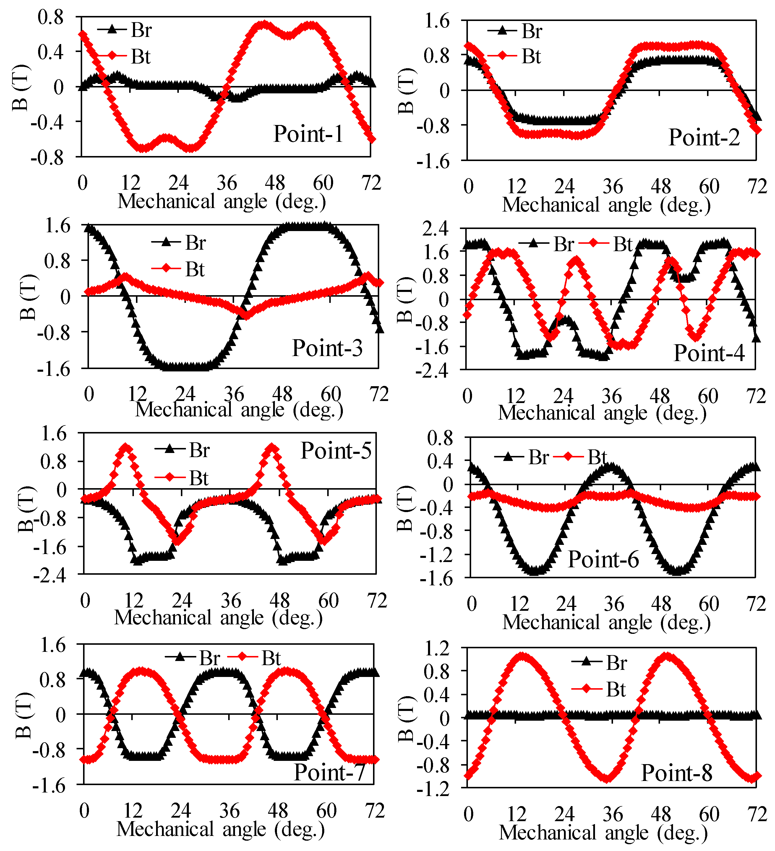
2.2. Core Loss Calculation Model

To consider the effect of rotational magnetization on core loss, the core flux density is decomposed in the radial and tangential directions, namely Br and Bt. Since at any moment the core flux density can be regarded as the vector sum of Br and Bt [20], the core loss is the sum of two components due to alternating magnetizations in the radial and tangential directions:
P f = k h f ( B r m β + B t m β ) + 2 π 2 k c f 2 ( B r m 2 + B t m 2 ) + 8.76 k e f 1.5 ( B r m 1.5 + B t m 1.5 )
where kh, kc, and ke are the coefficient of hysteresis loss, additional loss, and eddy current loss, respectively; f is the alternating current frequency; and Brm and Btm are the maximum values of the radial and tangential components of the flux density, respectively.
It should be noted that the hysteresis loss Ph is mainly affected by the local hysteresis loop, whereas the eddy current losses Pe and the additional losses Pc are mainly influenced by the harmonic components [19,21]. After taking into account the local hysteresis loop and the impact of the harmonic components on the core loss, the equation for the calculation of hysteresis loss should be modified to (2), and the equation for the calculation of unit volume eddy current losses and additional losses should be modified to (3).
P h = k h f ( j = 1 N p r B r m j 2 + j = 1 N p t B t m j 2 )
P c + P e = 2 π 2 k c f 2 k = 0 k 2 ( B r m k 2 + B t m k 2 ) + 8.76 k e f 1.5 k = 0 k 1.5 ( B r m k 1.5 + B t m k 1.5 )
where Npr and Npt are the number of hysteresis loops within one cycle of Br and Bt, respectively; Brmj and Btmj are the hysteresis amplitude of the jth hysteresis loops in the radial and tangential directions, respectively; and Brmk and Btmk are the amplitude of the kth harmonic component in the radial and tangential directions, respectively.
A mathematical model proposed to consider the effect of the DC magnetization component on hysteresis loss is shown in Equation (4) [22], where kdc and α are constants with the average values of kdc = 0.65 and α = 2.1, respectively, by numerically fitting five silicon steel sheet materials in [23], Phdc and Ph are the hysteresis loss considering the DC magnetization component or not, respectively, and Bdc is the value of the DC magnetization component.
P h d c = P h ( k d   c B d c α + 1 )
By the time-step FEM, the calculation procedure of core loss is follows: firstly, the stator and rotor cores are divided into small elements by the FEM. Secondly, the flux density of each element within one magnetization cycle is obtained. Thirdly, based on MATLAB, the core loss of each element is obtained. Finally, the total core loss of all elements is obtained by adding together the core loss of each element.

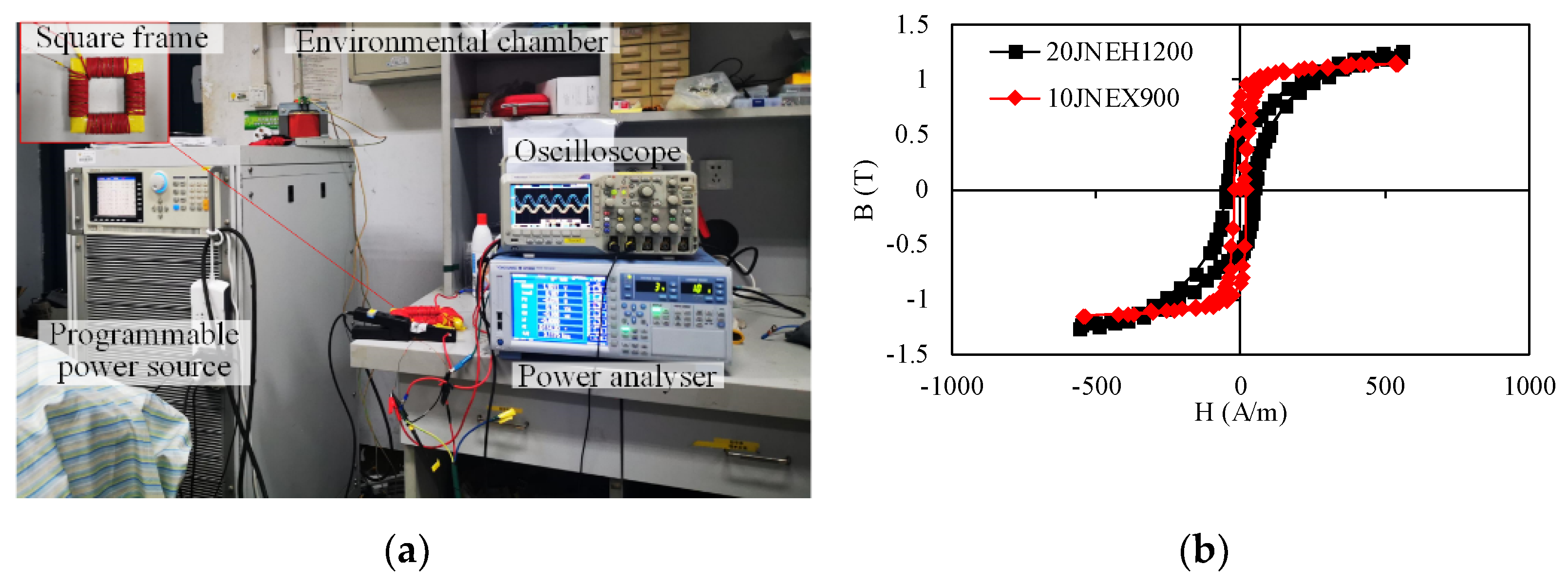
3. Calculation of Core Loss Coefficients

In this section, the core loss coefficients of each loss component are determined by tests on a sample module using an AC measurement system for soft magnetic materials used in the prototyped FSPM machine. The experimental setup consists of a programmable AC power supply (Chroma 61512), which can output AC/AC+DC voltages directly, a power analyzer, an oscilloscope, and voltage and current probes as shown in Figure 4a. The sample module is made of two silicon steel sheets, namely 10JNEX900 (0.1 mm) and 20JNEH1200 (0.2 mm). The cross-section of the test object is a silicon steel square frame with a primary winding N1 and a secondary winding N2 wrapped around the core in turn. The number of turns for both the primary and secondary windings is 80.
The flux density B and the effective field strength He can be calculated as [19,24]
ϕ ( t ) = 1 N 2 0 t e 2 ( t ) d t
ϕ m ( t ) = ϕ ( t ) 1 T 0 T ϕ ( t ) d t
where T is the time period, e2 is the instance voltage waveform of the measuring coil, i(t) is the current waveform measured in the excitation coil, and Le is the effective length of the silicon steel sheets.
The iron loss can be calculated as
B ( t ) = ϕ m ( t ) S
H e ( t ) = N 1 i ( t ) L e
P s e = 1 ρ V T 0 T i ( t ) e 2 ( t ) d t
where ρ and V are the density and volume of the silicon steel sheets, respectively, and S is the equivalent cross-sectional area.
The tested B-H magnetization curves of the silicon steel sheets are shown in Figure 4b. The loss coefficients can be obtained by
P s c = k h M f B m 2 + k e M f 2 B m 2 + k c M f 1.5 B m 1.5
where M is the mass of a silicon steel square frame.
Based on the MATLAB platform, the magnetic specific loss obtained from the test at each frequency was fitted using the least-squares method (LSM) with the following objective function.
B = B 1 B m [ P s c P s e P s e ] 2 = min
where Psc and Pse are the calculated and measured specific loss, respectively.
As a result, the loss coefficients kh, ke, and kc of 20JNEH1200 are 188, 0.079, and 2.01, and for 10JNEX900 they are 143, 0.0154, and 1.3, respectively.

4. Soft Iron Material and Driver Harmonics Effects

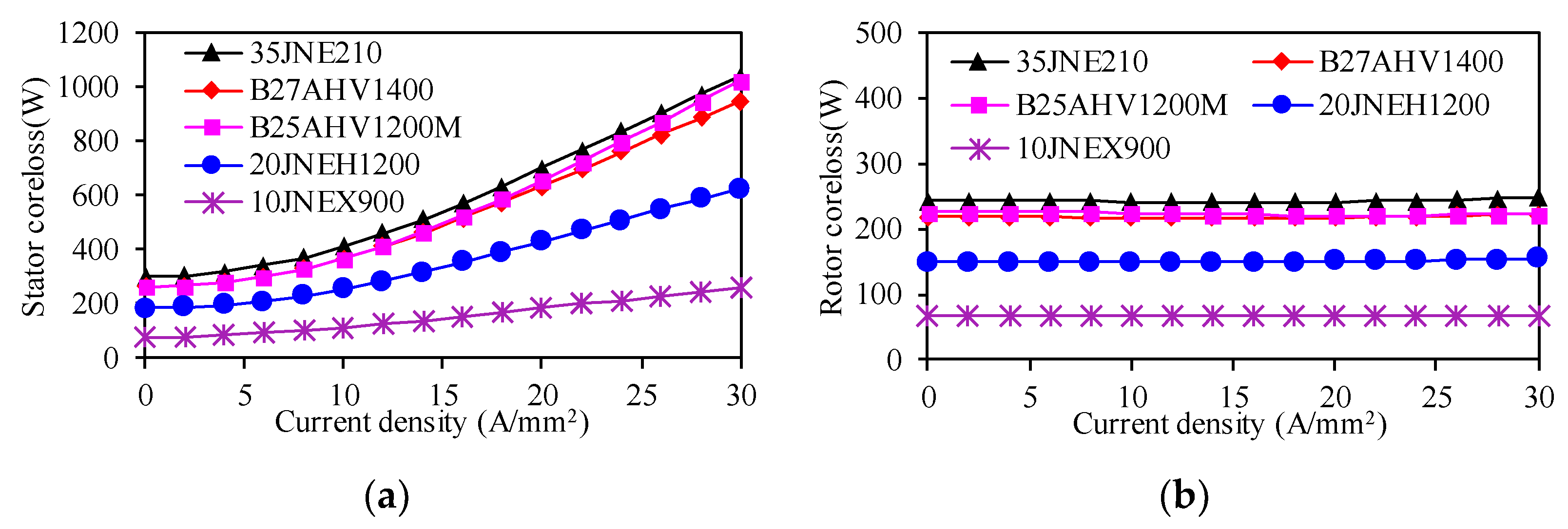
4.1. Effects of Soft Iron Materials on Core Loss

Under a sinusoidal current as the power supply excitation, Figure 5 shows the effects of different soft iron materials on stator and rotor core losses, respectively. As the armature’s current density increases, the stator core loss shows a nonlinear increasing trend. However, the core loss of the rotor is almost unaffected. On the other hand, as the thickness of the silicon steel sheet decreases, both the stator and rotor core losses gradually reduce. For machines with a high fundamental frequency, choosing the proper silicon steel sheet can help improve the efficiency of the machine.

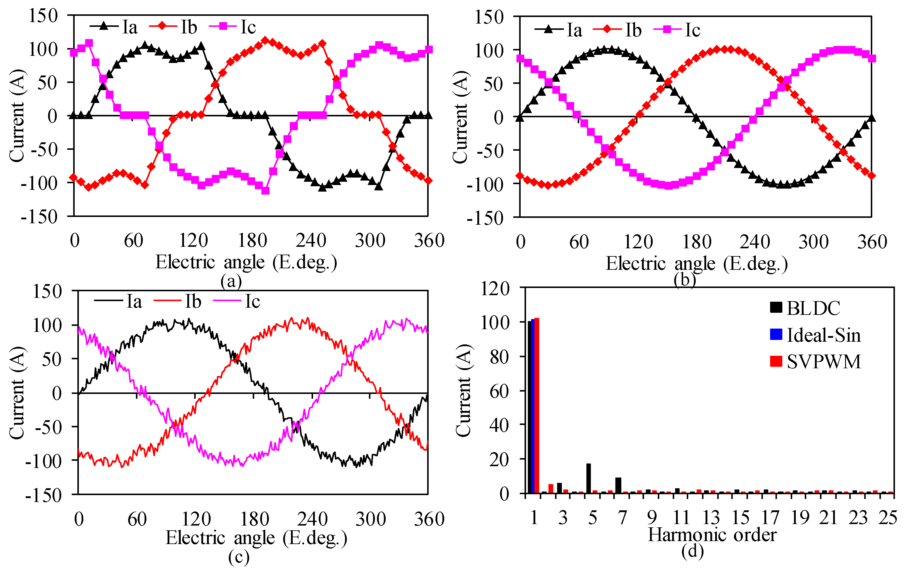
4.2. Effect of Driving Modes on Core Loss

By reference to the ideal sinusoidal current, a coupled magnetic field–circuit method was used to study the variation in core loss under two classical drive methods, namely BLDC (PWM_ON) and BLAC (SVPWM). The waveform and harmonic content of the phase current under rated operation conditions with different driving methods are shown in Figure 6. It was found that the THD (total harmonic distortion) of the current is 19.87% and 6.95% under the BLDC and BLAC driving methods, respectively, where the switching frequency of SVPWM is 40 kHz.
The effects of different frequencies on the stator and rotor core losses are shown in Figure 7. It can be seen that the core loss shows an obvious tendency to increase with the higher frequency. When the ideal sinusoidal current source is used to drive the machine, the calculated core loss is lower than those driven by the BLDC or BLAC methods. Obviously, the effect of different driving methods on the stator core loss is more pronounced than on the rotor core loss, and the stator core loss is dominant.

5. Verification

Since the prototype machine is still being processed, the core loss calculated using commercial FEA software was compared with and used to verify the numerical calculation of the core loss values used in this paper, as shown in Figure 8. Figure 8a,b show the core loss of the stator and rotor calculated by different calculating methods. The loss data in the left figure were calculated by commercial finite element software (ANSYS EM). The loss data in the right figure were calculated by the NCM. It can be seen that the results of the two methods of calculating losses are in the same trend, and the loss at low frequencies is very close to that obtained using the commercial FEM. However, at high frequencies, due to the consideration of DC bias and hysteresis loops, the calculated core loss is larger, which is ignored in the FEM.

6. Conclusions

A numerical method for calculating the core losses of a FSPM machine is proposed and implemented in this paper, where the DC-bias magnetization component and the local hysteresis loops as well as harmonic effects are considered simultaneously. Compared with commercial FEM software, the validity of the proposed analysis method is verified. Through this research, the following conclusions were drawn.
1. Based on the NCM method, the core loss of different stator and rotor materials was compared. It was found that the core loss of the stator and rotor gradually decreases with the decrease in the silicon steel sheet’s thickness. When the current density is 20 A/mm2, the core loss of a 0.1 mm thickness silicon steel sheet is 73.6%, 70.9%, and 71.8% lower than that of the 0.35 mm, 0.27 mm, 0.25 mm, and 0.2 mm thickness silicon steel sheets, respectively. The variation in rotor loss is similar to that of the stator.
2. Compared with the ideal sine wave power supply, the stator iron loss of the BLDC driving mode and the SVPWM driving mode increases by 20% and 16% during rated operation, respectively, while the rotor iron loss increases by 3.7% and 5.3%, respectively. It was found that the rotor core loss was less affected by the current amplitude and driving method at the same frequency, whereas the stator core loss was greatly affected by the current amplitude and the driving method.

Author Contributions

Conceptualization, W.Y. and W.H.; methodology, W.Y.; software, W.Y.; validation, W.Y. and Z.Z.; formal analysis, W.Y.; investigation, W.Y.; resources, W.Y.; data curation, W.Y.; writing—original draft preparation, W.Y.; writing—review and editing, W.Y., W.H. and Z.Z.; supervision, W.H.; project administration, W.H.; funding acquisition, W.H. All authors have read and agreed to the published version of the manuscript.

Funding

This work was supported in part by the National Natural Science Foundation of China under Grant 51777032, and the Key R&D Program of Jiangsu Province under Grant BE2020015.

Conflicts of Interest

The authors declare no conflict of interest.

References

  1. Gerada, D.; Zhang, H.; Xu, Z.; Calzo, G.L.; Gerada, C. Electrical machine type selection for high speed supercharger automotive applications. In Proceedings of the 19th International Conference on Electrical Machines and Systems (ICEMS), Chiba, Japan, 13–16 November 2016; pp. 1–6. [Google Scholar]
  2. Steinmetz, C.P. On the law of hysteresis. Proc. IEEE 1984, 72, 196–221. [Google Scholar] [CrossRef]
  3. Bertotti, G.; Boglietti, A.; Chiampi, M. An improved estimation of core losses in rotating electrical machines. IEEE Trans. Magn. 1991, 27, 5007–5009. [Google Scholar] [CrossRef]
  4. Zhu, J.G.; Ramsden, V. Improved formulations for rotational core losses in rotating electrical machines. IEEE Trans. Magn. 1998, 34, 2234–2242. [Google Scholar] [CrossRef]
  5. Štumberger, B.; Hamler, A.; Goričan, V. Accuracy of core loss estimation in induction motors by using different core loss models. J. Magn. Magn. Mater. 2004, 272, 1723–1725. [Google Scholar] [CrossRef]
  6. Pei, R.; Zhang, X.; Zeng, L.; Li, S. Studies of high-frequency iron core loss for synchronous electric machines used in electric vehicles. In Proceedings of the 2017 20th International Conference on Electrical Machines and Systems (ICEMS), Sydney, Australia, 11–14 August 2017; pp. 1–4. [Google Scholar]
  7. Liu, X.; Liu, G.; Han, B. A Loss separation method of a high-speed magnetic levitated PMSM Based on drag system experiment without torque meter. IEEE Trans. Ind. Electron. 2018, 66, 2976–2986. [Google Scholar] [CrossRef]
  8. Frljić, S.; Trkulja, B. Two-step method for calculation of eddy current losses in a laminated transformer core. IET Electr. Power Appl. 2020, 14, 1577–1583. [Google Scholar] [CrossRef]
  9. Boubaker, N.; Matt, D.; Enrici, P.; Nierlich, F.; Durand, G. Measurements Of Iron Loss in PMSM stator cores based on cofe and sife lamination sheets and stemmed from different manufacturing processes. IEEE Trans. Magn. 2018, 55, 1–9. [Google Scholar] [CrossRef]
  10. Al-Timimy, A.; Giangrande, P.; Degano, M.; Xu, Z.; Galea, M.; Gerada, C.; Calzo, G.L.; Zhang, H.; Xia, L. Design and losses analysis of a high power density machine for flooded pump applications. IEEE Trans. Ind. Appl. 2018, 54, 3260–3270. [Google Scholar] [CrossRef]
  11. Tong, W.; Sun, R.; Zhang, C.; Wu, S.; Tang, R. Loss and thermal analysis of a high-speed surface-mounted PMSM with amorphous metal stator core and titanium alloy rotor sleeve. IEEE Trans. Magn. 2019, 55, 1–4. [Google Scholar] [CrossRef]
  12. Ma, J.; Zhu, Z.Q. Optimal split ratio in small high speed PM machines considering both stator and rotor loss limitations. CES Trans. Electr. Mach. Syst. 2019, 3, 3–11. [Google Scholar] [CrossRef]
  13. Fang, S.; Liu, H.; Wang, H.; Yang, H.; Lin, H. High power density PMSM with lightweight structure and high-performance soft magnetic alloy core. IEEE Trans. Appl. Supercond. 2019, 29, 1–5. [Google Scholar] [CrossRef]
  14. Tong, W.; Dai, S.; Wu, S.; Tang, R. Performance comparison between an amorphous metal PMSM and a silicon steel PMSM. IEEE Trans. Magn. 2019, 55, 1–5. [Google Scholar] [CrossRef]
  15. Li, Y.; Cheng, H.; Lin, Z.; Deng, K.; Yang, M. A modified characterization method for core loss calculation under rotational magnetization. IEEE Trans. Magn. 2021, 57, 1–6. [Google Scholar] [CrossRef]
  16. Thomas, A.S.; Zhu, Z.Q.; Li, G.J. Electromagnetic loss investigation and mitigation in switched flux permanent magnet machines. In Proceedings of the 2014 International Conference on Electrical Machines, Berlin, Germany, 2–5 September 2014; pp. 1146–1152. [Google Scholar]
  17. Mo, L.; Quan, L.; Zhu, X.; Chen, Y.; Qiu, H.; Chau, K.T. Comparison and analysis of flux-switching permanent-magnet double-rotor machine with 4QT used for HEV. IEEE Trans. Magn. 2014, 50, 1–4. [Google Scholar] [CrossRef]
  18. Yuan, J.; Meng, D.; Lian, G.; Zhang, J.; Li, H.; Ban, F. The stator slot-type optimization of electrical excitation flux-switching motor and its maximum torque/copper loss control. IEEE Trans. Appl. Supercond. 2019, 29, 1–5. [Google Scholar] [CrossRef]
  19. Zhu, S.; Cheng, M.; Dong, J.; Du, J. Core loss analysis and calculation of stator permanent-magnet machine considering DC-biased magnetic induction. IEEE Trans. Ind. Electron. 2014, 61, 5203–5212. [Google Scholar] [CrossRef]
  20. Tong, W.; Li, S.; Sun, R.; Sun, L.; Tang, R. Modified core loss calculation for high-speed PMSMs with amorphous metal stator cores. IEEE Trans. Energy Conver. 2021, 36, 560–569. [Google Scholar] [CrossRef]
  21. Zhu, S.; Wang, H.; Zhang, J.; Lu, Z.; Cheng, M. Fast calculation of carrier harmonic loss in permanent magnet of IPMSM under PWM VSI supply over entire working range. IEEE Trans. Energy Conver. 2019, 34, 1581–1592. [Google Scholar] [CrossRef]
  22. Simao, C.; Sadowski, N.; Batistela, N.; Bastos, J. evaluation of hysteresis losses in iron sheets under DC-biased inductions. IEEE Trans. Magn. 2009, 45, 1158–1161. [Google Scholar] [CrossRef]
  23. Zhu, S.; Cheng, M.; Hua, W.; Cai, X.; Tong, M. Finite element analysis of flux-switching PM machine considering oversaturation and irreversible demagnetization. IEEE Trans. Magn. 2015, 51, 1–4. [Google Scholar] [CrossRef]
  24. Wang, J.; Hu, Y.; Cheng, M.; Li, B.; Chen, B. Bidirectional coupling model of electromagnetic field and thermal field applied to the thermal analysis of the FSPM machine. Energies 2020, 13, 3079. [Google Scholar] [CrossRef]
Figure 1. Cross-section of a 12/10 FSPM machine and eight key points. (a) 2D machine cross-section, (b) eight key points.
Electronics 10 01076 g001
Figure 2. Radial and tangential flux density waveforms of eight key points due to PMs.
Electronics 10 01076 g002
Figure 3. Flux density vector trajectories of the key eight points in the rotor and stator cores.
Electronics 10 01076 g003
Figure 4. AC measurement system for soft magnetic materials. (a) Test platform and (b) magnetizing characteristics of the silicon steel sheet.
Electronics 10 01076 g004
Figure 5. Effect of soft iron materials on core loss. (a) Stator core loss and (b) rotor core loss.
Electronics 10 01076 g005
Figure 6. The current and harmonic content of different driving methods. (a) BLDC, (b) Ideal-Sin, (c) SVPWM, (d) Current THD.
Electronics 10 01076 g006
Figure 7. Core losses of the stator and rotor under three driving methods.
Electronics 10 01076 g007
Figure 8. Comparison of core losses by FEM and NCM. (a) Stator core loss and (b) rotor core loss.
Electronics 10 01076 g008
Table 1. Main parameters of the 12/10 FSPM machine.
ParametersValues
Number of stator slots, Ps12
Number of rotor pole pairs, Pr10
Stator outer diameter, mm173
Stator inner diameter, mm112
Axial iron core length, mm43
Number of turns/slot18
Winding layers2
Peak power, kW54.7
Rated speed, rpm10,000
Rated torque, Nm26.52
Rated power, kW27.7
Rated current, A100
Current density, A/mm210
Rated frequency, Hz1666.7
Silicon steel sheet material20JNEH1200
Permanent magnet materialN35UH
Publisher’s Note: MDPI stays neutral with regard to jurisdictional claims in published maps and institutional affiliations.

