Article

Multiple Sensor Fault Detection Algorithm for Fault Tolerant Control of BLDC Motor

Department of Electrical Engineering, Incheon National University, Incheon 22012, Korea
*
Author to whom correspondence should be addressed.
Senior Member, IEEE.
Electronics 2021, 10(9), 1038; https://doi.org/10.3390/electronics10091038
Submission received: 6 April 2021 / Revised: 19 April 2021 / Accepted: 26 April 2021 / Published: 27 April 2021

Abstract

:
A direct redundancy-based fault tolerant control system (FTCS) is proposed for the operation of a brushless DC (BLDC) motor in the case of multiple sensor failures. The presented method expands on the previously published work that dealt with the failure of a single Hall-effect sensor. In this paper, a novel algorithm is developed along with the new experimental scheme and the FTCS can deal with the failure of up to two Hall-effect sensors. The fault tolerant control (FTC) algorithm is based on three conditions and is designed to deal with any scenario of the sensor faults. Simulation was performed and presented experimental results show effectiveness and validation of the method. The method can be implemented with ease, is fast and does not require high end processors.

1. Introduction

Nowadays, there is increased drive towards more and more electric transportation and initiatives are taking place around the globe. In a modern electric vehicle, there are numerous electric motors [1], however, permanent magnet synchronous motor (PMSM) used for propulsion of the vehicle is very important. A propulsion motor needs to be highly reliable and robust [2]. Furthermore, PMSMs find application in aerospace industry [3], automotive industry [4], and consumer appliances [5]. Higher efficiency, high power density, low maintenance costs, wide speed range, robustness and high reliability are a few of the features a PMSM offers [1,6,7]. For high reliability, robustness and applications where human safety is crucial, these require intelligent systems such as a fault tolerant control system (FTCS). Therefore, recently, there has been increased focus towards FTCS for PMSM faults [2,8,9].
Brushless DC (BLDC) is a type of PMSM, and for the control of motor, often discrete Hall-effect sensors provide the required rotor position. The Hall-effect sensor position feedback information is used for electronic 120° commutation of the BLDC motor phases [10]. As a position sensing element, a Hall-effect sensor may fail any time during the life of the motor. Therefore, when one of the Hall-effect sensors becomes faulty or damaged, motor operation is severely affected and after two sensor failures, the motor comes to a complete stop. Such a scenario may result in very dangerous and life-threatening situations in the aerospace or automotive industries and such situations must be avoided at all costs. In order to maintain the motor operation with the damaged sensor, FTCS is required. The FTCS keeps the motor operating and functional till the maintenance can be performed or the damaged part can be replaced [11].
A BLDC motor system may suffer from various types of faults such as winding-related, inverter-related or position sensor-related faults. For the winding- and inverter- related faults, often motor design or inverter design is augmented. However, position sensor fault can completely be remedied using intelligent control system. For that purpose, there are several articles on FTC of position sensor fault. In the study of [12], a combinational circuit is designed for fault diagnosis and identification of one Hall-effect sensor. A BLDC motor start-up algorithm is also suggested with one of the three Hall-effect sensors damaged. Furthermore, limitations and shortcomings of the methods are discussed as well and experiments are performed to support the theory. The presented method deals with only one of the three Hall-effect sensor faults while increasing the component count, which may be an issue in terms of overall system reliability and the associated increased costs. The startup algorithm does work most of the time; however, it also fails in certain specific situations. A direct redundant Hall-effect sensor fault tolerant control is explained in [13]. Aqil and Jin Hur claim that the method is fast, however, only one of the three sensors can be considered faulty. Jun Cai et al. [14] describe diagnosis, identification and remedy of the Hall-effect sensor fault for a synchronous reluctance motor (SRM). Synthetic hybrid-integral-threshold logic is explained for diagnosis of the Hall-effect sensor faults. Each sensor fault is diagnosed and identified independently of the other sensors. The FTCS can coup with the damage of up to two Hall-effect sensors. Jun Cai et al. claim that their method is fast and can work efficiently during the transients as well. However, double sensor fault cases are not discussed and furthermore, the time taken by the FTC process is also not discussed. A double redundant fault tolerant control system is proposed to respond to inverter faults, Hall-effect sensor position sensor fault and motor winding faults for a UAV steering gear system [15]. A dual redundant BLDC motor is used as the main part of the system. The motor has redundant windings and redundant set of position sensors as well. Two sets of motors are used and operated independently in the UAV steering gear system. Hall-effect sensor faults are detected by the presence of zero vectors. Inverter faults are divided into two categories: (1) short circuit arm of the bridge, and (2) open circuit of the bridge arm. Upon detection of any of the faults, the system falls back to single redundancy mode and normal system operation continues. Nonetheless, Wei Dai et al. did not mention the range of the angles the system takes from fault diagnosis to fault identification and compensation, during which the drive executes incorrect motor phase currents. A single Hall-effect sensor fault is dealt with in [16]. An improved all pass filter is designed to add phase to the healthy sensor signals and therefore, compensate the faulty sensor signal. It is claimed that to avoid the current ripple in the transition to fault tolerant control, this improved circuit is proposed; nonetheless, the presented method only can deal with a single sensor fault. The authors in [17] explain the method for Hall-effect sensor faults of up to two sensors out of the three sensors. There are three rules which detect the Hall-effect sensor faults: (1) detection of the wrong sequence of the Hall-effect sensors, (2) a sector maximum limit is exceeded and, (3) a sector is shorter than the minimum limit. After the fault detection, the control system shifts to either two sensors or a one sensor operation. The method is supported with experimental results. Nonetheless, it is not explained how the method may work during acceleration or deceleration, and furthermore, the time the system takes to diagnose and identify the sensor faults is not discussed.
Effects of the failure of the Hall-effect sensor on a BLDC motor drive are discussed, where, value-based fault detection, Fast Fourier Transform (FFT) and Spectral Energy Density (SED) are used for fault identification. Since the method uses FFT and SED, therefore, the recommended scheme takes 113 ms to diagnose and identify the fault [18]. The authors in [19] explain fast fault diagnosis technique, where the Hall-effect sensor signals are sampled at high frequency and the sampling instants are considered as a fast counter. Therefore, whenever the counter exceeds a certain limit or falls short of the threshold values, that raises a fault flag. The suggested method offers quick fault diagnosis; however, there are acceleration constraints. A combination of signal injection technique and Hall-effect sensor is suggested along with a fault robust speed estimation. Such a system can be used where it conforms to Automotive Safety Integrity Level (ASIL) and Safety Integrity Level (SIL) [20]. Nonetheless, the combined approach can only be used for motors with saliency and at speeds more than 0.1 p.u. The authors in [21,22] describe a FTC method, which, in some situations can take up to electrical 360° to identify the fault and furthermore, has high computation cost because it uses Vector Tracking Observer (VTO) and Fourier series, for which calculation of the Fourier coefficients is necessary. Furthermore, in case of a multiple sensor fault, it is not possible to start the motor in a known direction, hence the method cannot be used for the applications where frequent stops are required, such as electric scooters. The authors in [23] describe Hall-effect sensor faults by stating three different approaches: The first method discusses the state-sensitive technique where the last three states of sensors are kept in memory and the controller continuously compares the current state with the stored pattern and if a changed sequence is detected, that means that there is a fault. The second approach describes the use of the sensor transition order, by saving the last two transitions in memory. A modification in transition sequence points to a sensor fault. The third method works by following a conditions-based approach which, in some situations, can also result in wrong fault type diagnosis. Such a fault is rectified after further rotation of the motor. All the three methods are modest; however, they rely on an assumption that the motor is continuously running when the fault occurs, which, in certain applications, is not the case. Moreover, at some occasions, the FTC requires up to 10 ms for the remedial strategy to be adopted and for these 10 ms, an incorrect commutation sequence causes transient currents which, consequently, result in huge speed variations. A fault tolerant control algorithm is devised; simulation and experimental results are discussed as well. A virtual Hall-effect sensor signal is created off each of the other two Hall sensors; furthermore, each pair of Hall sensor signals is checked for fault and compared with the other pair of Hall sensor signals. The sensor maintains constant value as the rotor rotates, and is diagnosed and identified as the failed sensor. For compensation, the virtually generated signal is replaced with the faulty sensor’s signal. The algorithm does not work at very low speeds and suggests implementation as a standalone subsystem [24]. Hall-effect sensor fault is detected by an acceleration threshold and identification of a damaged sensor is performed using comparative statements [25]. Comparative statements rely on the point that under healthy motor action, the sensor value is required to transition between high and low levels. Nevertheless, the case is not discussed when fault occurs while the threshold is not triggered or in the event the sensor retains the value of 0 or 1, permanently. Moreover, the techniques that depend on the motor parameters such as sensorless algorithms, are favorable in terms of cost savings and decrease the overall component count; however, such methods suffer from changes in motor parameter values. Sensorless algorithms are very complex and computation heavy, thus, requiring high-end digital signal processors (DSP). Moreover, sensorless methods work well for the motors with salient rotor, while for non-salient motors, sensorless control results are not good at low speeds or with load variations [26].
This paper proposes a new algorithm based on a direct redundant idea to deal with the fault of up to two Hall-effect sensors. The single sensor FTCS presented in [13] fails when double sensor fault is considered; therefore, here, a novel algorithm is devised to deal with the double sensor faults. Furthermore, a completely new experimental scheme is devised to validate the algorithm. Section 2 explains the effects of the damaged sensor, sensor faults and remedy of the faults; Section 3 explains the algorithm; MATLAB/Simulink simulation is performed in Section 4; experimental results are presented in Section 5; Section 6 is on the comparison of the presented method with the other published techniques and the conclusion is in Section 7.

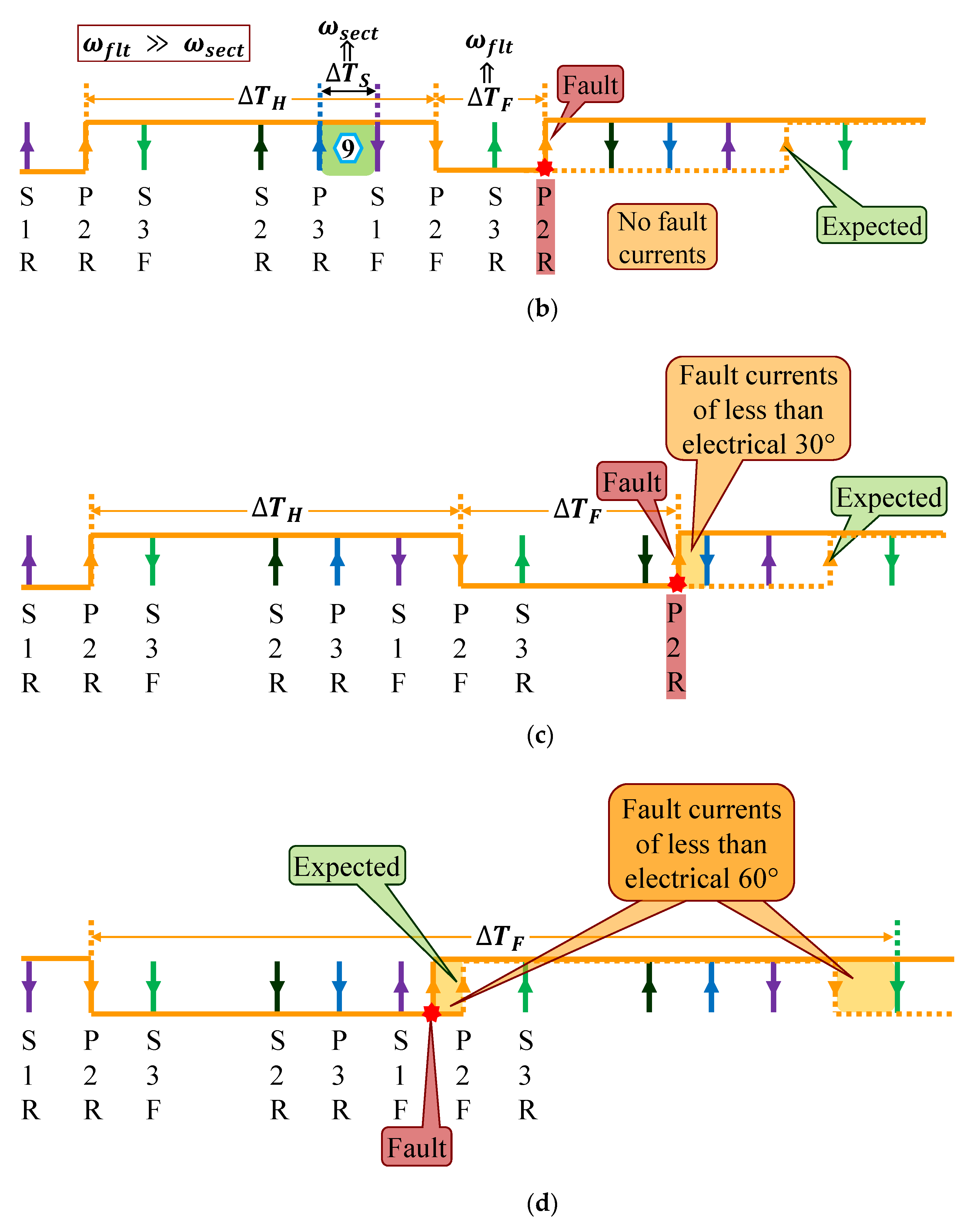
2. Effect of Hall-Effect Sensor Fault, Fault Types and System Response

2.1. Single Hall-Effect Sensor FTCS

Earlier, authors have published the work on single sensor FTCS based on direct redundant sensors [13]. The direct redundant sensors consist of a set of primary and a set of secondary sensors as shown in Figure 1. Primary are for the main motor operation while the secondary sensors offer fast fault detection, motor startup in case of the sensor failure and increased availability of torque.

2.2. Multiple Hall-Effect Sensor FTCS

For control of a BLDC motor, a rotor position feedback device is essential. Therefore, for various applications, Hall-effect sensors are used. Under normal operation of the motor, Hall-effect devices provide the required rotor position information, however, in the aftermath of sensor failures, this information is lost and the motor cannot continue the regular operation. Figure 2a shows the motor response when one of the Hall-effect sensors is damaged and Figure 2b shows the motor phase currents after the malfunction of two Hall-effect sensors. Hall-effect sensor, P1, fault causes the motor speed to drop from 563 rpm to 358 rpm, which is 36% reduction in motor speed. Furthermore, the current amplitudes approximately double while Phase-U and Phase-W only conduct unidirectional currents. Figure 2b shows that motor stops completely after two Hall-effect sensors, i.e., P1 and P2 malfunction and remain zero permanently. A double sensor fault causes the Phase-U leg of the bridge to not gain any signal at all, and thus, Phase-U current remains zero permanently. Therefore, after Hall-effect sensor faults, a FTC system is required to sustain the motor operation. A double Hall-effect sensor fault here is assumed that sensor faults occur in succession, i.e., Hall-effect sensor P1 malfunctions at time t 1 and Hall-effect sensor P2 faults later on at time t 2 during the motor operation, such that there is time for P1 to be remedied.
Fault detection and identification logic for Hall-effect sensor P1 is explained and the possible fault cases of one sensor fault are shown in Figure 3. Figure 3a shows the healthy Hall-effect sensor P1 with respect to the rest of the sensor transitions. The first sensor fault is detected mainly by three conditional statements in the main program. Condition-one (conditions are described later in Section 3) compares the speed computed by the edges of the Hall-effect sensor P1 to motor speed computed in sector-5, as shown in Figure 3b. Motor speed is calculated by the equations.
ω h = 6 5 p Δ T x
ω s e c t = 5 p Δ T y
where ω h , ω s e c t , p , Δ T x , Δ T y is mechanical speed calculated by electrical 180° edges, speed calculated by electrical 30° edges, rotor pole pairs, sector time, healthy sensor time, x can be H or F, and y can be S or F, respectively. S is for sector time and F is for fault time; with F, the motor speed will be ω f l t . Now, an erroneous P1 edge causes the time related to electrical 180° to be very short, and as a result, motor speed appears to be morethan double within electrical 90°, which is evident from Equation (1) above. Therefore, it is assumed that it is not possible under normal operation of the motor, and hence the fault detection by condition-one. All the fault cases of the Hall-effect sensor P1 edge appearing before Hall-effect sensor S1 will be detected by condition-one. For the event when the P1 edge appears after S1 and before P2, such a case is sensed by comparing the transition times of P1 to P2. Under normal operation and in counter-clockwise direction, transition time of P1 will always be greater than P2, however, malfunctioning of the sensor P1 may result in the edge to occur earlier than P2, and hence the fault detection by condition-two. Similarly, a P1 edge between P2 and S3 is also detected by analogous condition to condition-two. Cases detected by condition-two may cause incorrect commutation of motor phase currents of less than electrical 30° and are depicted in Figure 3c. A damaged sensor may not trigger an edge or the transition happens after S3, and before the expected time, may be detected by condition-three. Condition-three distinguishes the fault by detecting a sudden decrease in the motor velocity, as is evident from Equation (2). The two fault cases of condition-three are illustrated in Figure 3d. Fault detection by condition-three may cause fault currents of a maximum of electrical 60°. All the fault cases shown in Figure 3 are regarding the rising edge, however, for the falling edge, the method will be the same as rising edge. Hall-effect sensor P2 fault cases are depicted in Figure 4 and the fault detection logic is the same as explained for the Hall-effect sensor P1.
Fault detection, identification and compensation explained here was for counter- clockwise (CCW) rotation of the motor, however, for the clockwise (CW) direction, the same method may be used with only the transition order in reverse. Moreover, the method does not depend on load variations since this method only relies on sensor edges.

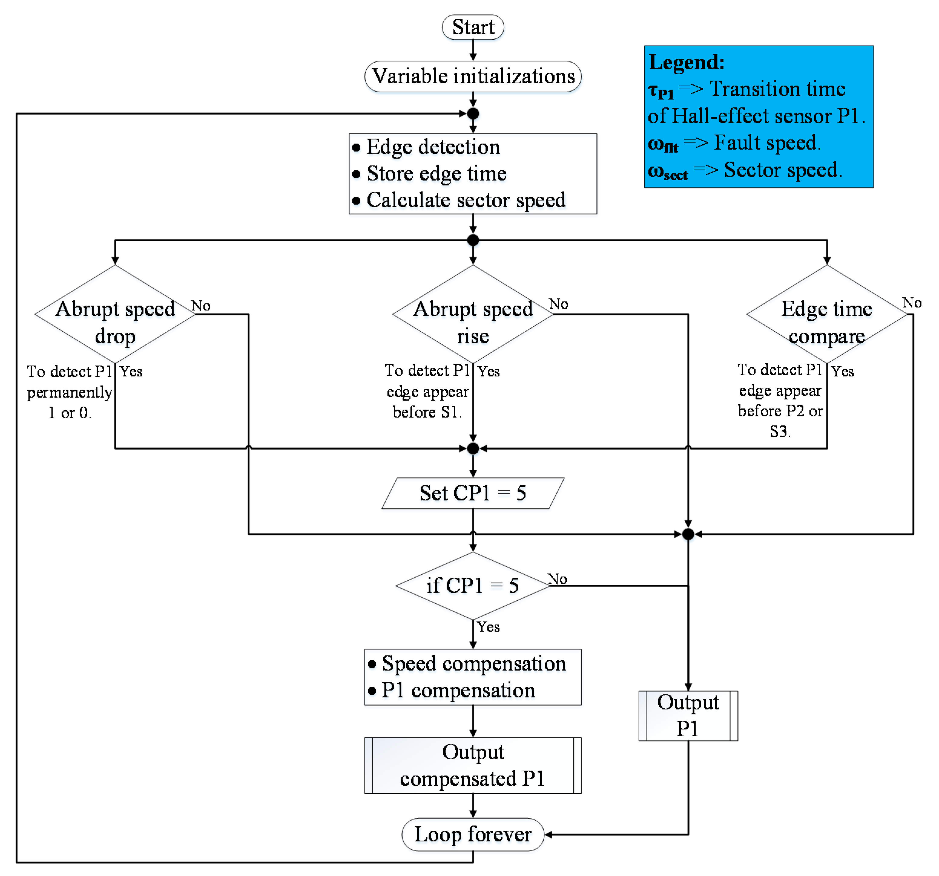
3. Explanation of Program Flowchart of the FTCS

Flowchart for the logic of the main program is shown in Figure 5. At the start of each cycle, the program checks whether a transition occurred. Transition is detected by sensing sensor output level change. Afterwards, transition time is stored and individual sector speed is calculated. The edge time and sector speeds are subsequently utilized by the three conditions to detect the individual sensor faults. Upon detection and identification of the damaged sensor, the respective sensor condition is set. Additionally, the malfunctioned Hall-effect sensor signal is replaced by a controller generated compensation signal, since one of the sensors is damaged, therefore, speed is not calculated for the faulty sensor and the compensated speed is used. The program logic is similar for fault detection, identification and compensation of Hall-effect sensor P2, as well.
A MATLAB/Simulink simulation model was used for testing the main program logic, which was designed and published in earlier work of the authors [13].

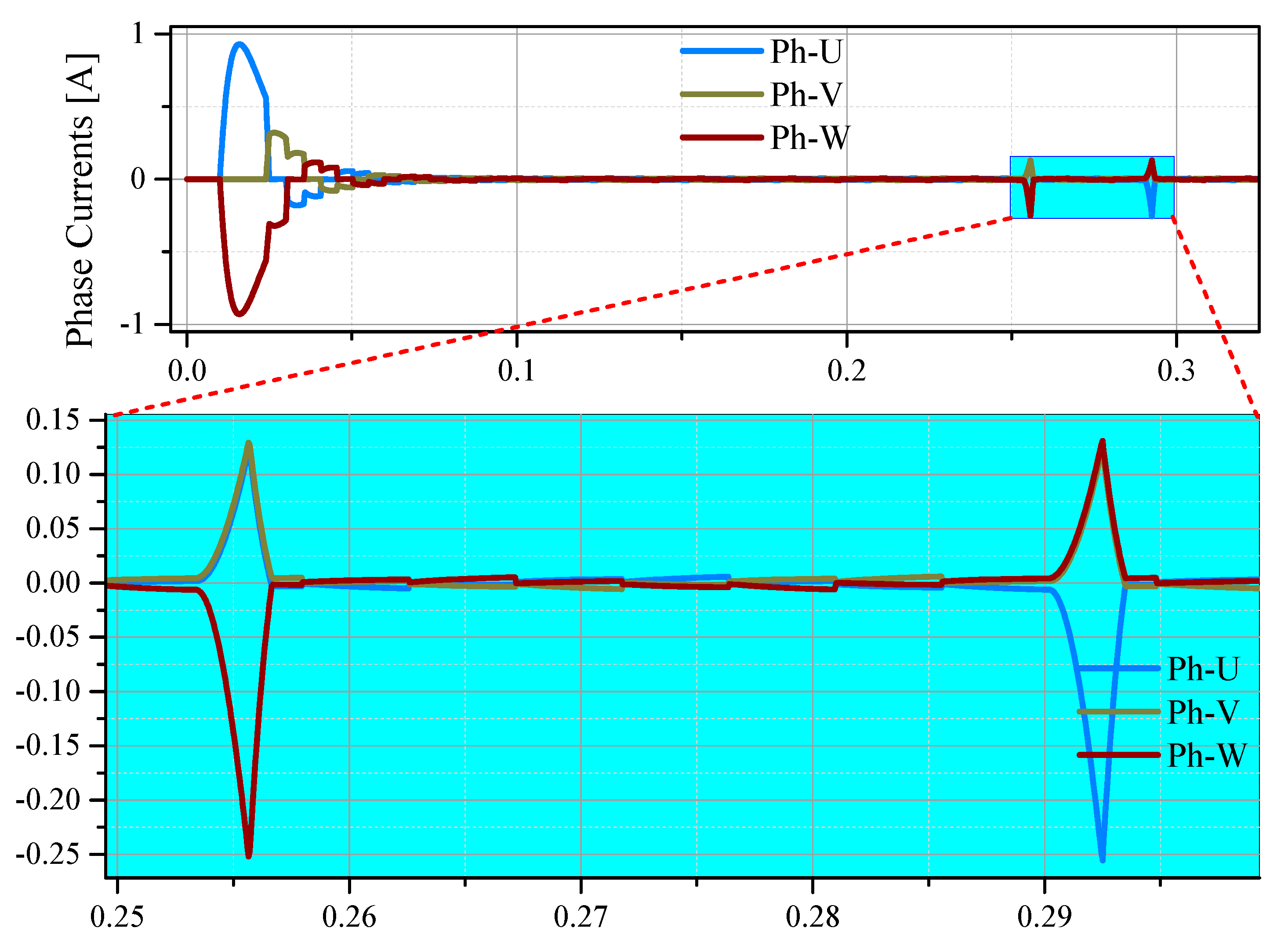
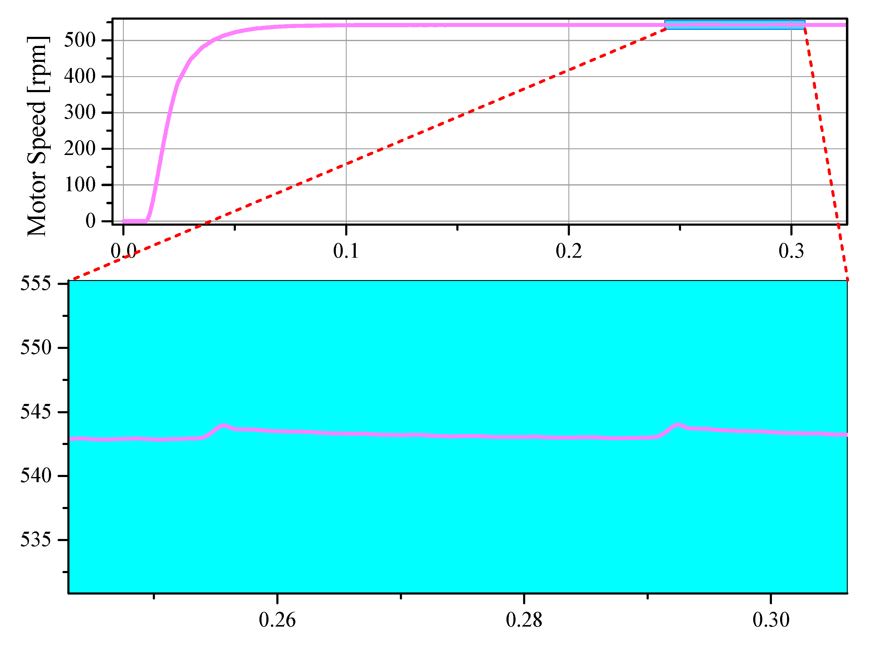
4. Validation of the Algorithm by a MATLAB/Simulink Simulation

An open loop MATLAB/Simulink simulation of the motor is performed as the drive system used during the experiments is open loop control as well. Block diagram of the simulation is shown in Figure 6. The reference speed is converted to the input of the inverter by the PI controller. Therefore, motor phase currents are controlled by the Hall-effect sensor commutation table. Hence, the motor speed is controlled. A double sensor fault is simulated where the sensor remains high after the fault and causes an electrical 30° transient currents. The motor used in the simulation is ideal and thus, the current drawn is close to zero. However, the fault transients are shown causing electrical 30° of the irregular currents for each of the sensor faults and are shown in Figure 7. The momentary changes in the motor speed caused by the faults are depicted in Figure 8. The speed bumps are approximately of 2 rpm. Moreover, if translated to change in a sector’s width at 540 rpm, the additional width in terms of electrical degrees results in 0.1111°. Such a small change in the sector width is inconsequential since speed computation based on the Hall-effect sensors is inherently noisy. Therefore, it does not affect the motor response severely. After that, a comparison of motor speed acceleration is performed with the faulty and healthy sensors. The speed comparison elaborates the effects of the control error and the speed error. Moreover, the results of the speed comparison simulation are shown in Figure 9. Here, it is noteworthy that the speed error is very small and therefore, the curves can be considered the same. Furthermore, since the speed calculated using Hall-effect sensors is noisy, thus, this very small error is not noticeable in the experimental results which are discussed in the next section.

5. Experimental Results and Discussion

In order to validate and verify the presented Hall-effect sensor FTC system for motor operation, experiments are performed. Table 1 describes the equipment used during the experiments.
Figure 10 shows the experimental scheme and the setup for the validation of the FTC system. The FTC algorithm for the Hall-effect sensor failures is implemented into the dSPACE box 1202. Six Hall-effect sensor signals from the motor are fed directly to the dSPACE box input channels, where the algorithm continuously search for sensor faults.
For the case of implementation on a micro controller, input capture channels can be used [27]. The output channels of dSPACE box provide three Hall-effect signals, which are fed to the motor driver for the motor operation. In case of fault of Hall-effect sensors, the FTC algorithm detects, identifies and compensates the faulty signals by internally generating virtual signals replacing the faulty sensor signals. Experiments were performed both at constant speed and at transient operation of the motor as well. The proposed method shows equally effective results for both the cases.
Figure 11 shows experiment results of the multiple sensor fault and compensation. Figure 11a shows the overall response of the system to the double sensor fault, while, Figure 11b shows the zoomed view of P1 sensor fault, detection and compensation. Hall-effect sensor P1 remains zero permanently and is detected by the following edge of Hall-effect sensor S2. From the instant of the fault and to the detection of the fault, the motor currents are incorrect and wrong commutation lasts for electrical 30°. Afterwards, the motor currents are compensated and regular motor operation continues. Hall-effect sensor P2 fault response is similar, therefore, is not shown as zoomed view. A fault where Hall-effect sensor P1 or P2 may remain 0 or 1 permanently, will result in similar system response as shown in Figure 11. Figure 11b show that due to the fault Phase-V conducts for electrical 150° while Phase-W conducts for electrical 210°. Transient currents last till the fault is compensated. FTCP1 is the controller generated compensation signal to replace Hall-effect sensor P1. Figure 11b shows that the fault causes the FTCP1 signal to have a low that lasts for electrical 210°, while the high lasts for electrical 150°. However, after the compensation, the signal periods become normal and symmetric.
A fault that causes the speed reading to be recorded more than double, compared to the last sector speed, is detected momentarily and does not cause any incorrect commutation. Moreover, motor phase currents show no signs of fault, as if fault never happened. The experimental results are shown in Figure 12. P1 and P2 sensor faults cause a sudden sharp increase in the motor speed within a very small electrical rotation. Thus, the fault is detected and compensated momentarily.
Results of the experiment showing faults detected by the comparison of the transition times are shown in Figure 13. P1 sensor fault is similar to the earlier explained case while P2 sensor fault show the system response for when P2 edge lies between the sensors P3 and S1. Motor currents start to increase after the P2 fault and subsequently drop to normal after detection and compensation of the fault at the sensor S1 edge. The fault in such a case can cause transient currents for up to electrical 30°.
A malfunction of a Hall-effect sensor will result in a fault that is detected by either of the three conditions mentioned in Figure 5. Therefore, the resulting system response will be similar to Figure 11, Figure 12 and Figure 13.
Furthermore, the experiments were performed at 560 rpm with a 3-polepair (PP) PMSM. At 560 rpm electrical 60° corresponds to 6 ms and electrical 60° is the maximum for the fault to be remedied. With the swift system response, there was no noticeable change in the speed readings. Thus, speed plots were omitted.

6. Comparison of the FTC Methods

An arduous task is to perform the comparison of all the presented methods in different published papers. For instance, the motor pole pairs, load conditions, microcontroller used, and speed at which experiments are performed vary from one article to the other. Therefore, it is very important to find the common basis on which the comparison can be performed. The common basis for this comparison is the motor rotation in terms of electrical degrees taken by the proposed technique, which is not affected by the above mentioned differences. Furthermore, since the time taken by the FTCS depends on speed, i.e., at low speeds, the time expended by FTCS will be longer than at higher speeds. Therefore, fault detection, identification, isolation, and compensation accomplished in the least number of electrical degrees may be called the most efficient technique and vice versa. Furthermore, only the papers that show experimental results and motor parameters are included in the comparison. In that respect, the authors in [19] ensure the FTC in the shortest possible time; nevertheless, the authors state that in case of excessive acceleration or deceleration, the algorithm needs to be turned off to avoid false alarms. The authors in [18] propose a non-invasive FTC approach by analyzing the motor line voltages, however, the presented design results in maximum electrical degrees to compensate for the fault. The rest of the suggested methods lie between the above mentioned two extremes and are provided in Table 2, with respect to the electrical degrees expended by the FTC technique.

7. Conclusions

A direct redundant fault tolerant control system for up to two Hall-effect sensor failures is presented. The method detailed in this paper is an extension of the previously published work on direct redundant fault tolerant control. The presented scheme is based on mainly three conditions to detect Hall-effect sensor fault. All the possible fault cases fall under these conditions. A fault detected due to the sudden speed change will cause electrical 0° of faulty currents and will swiftly be compensated. Moreover, all the other fault cases will be detected within either electrical 30° or at most electrical 60°. The main contribution is the development of the fault tolerant control algorithm. Simulation and experimental results of the designed and working system are presented. The results show effectiveness and validity of the proposed method. Future research can focus on the development of a motor startup method based on direct redundant sensors. Furthermore, the redundant sensors increase the component count, however, they offer fast fault detection, increased availability of torque, and motor startup in case of sensor faults.
This method is not affected by load change, signal noise or sensor offset generated issues since the fault detection and identification relies solely on sensor transitions only. The developed algorithm is general in the sense that it may be applied to any of the two sensors or may be extended to include more sensor failures.

Author Contributions

Conceptualization, M.A.; methodology, M.A.; validation, M.A.; resources, J.H.; writing—original draft preparation, M.A.; writing—review and editing, M.A. and J.H.; visualization, M.A.; supervision, J.H.; funding acquisition, J.H. All authors have read and agreed to the published version of the manuscript.

Funding

His work was supported by Industrial Strategic Technology Development Program of Korea Evaluation Institute of Industrial Technology (KEIT) (No. 20010132 and No. 20002745).

Conflicts of Interest

The authors declare no conflict of interest.

References

  1. Krall, F.; Gruebler, H.; Muetze, A. Analysis of the Angle Modulated Switching Strategy for Use with Fractional Horse Power BLDC Motors. IEEE Trans. Power Electron. 2020, 1. [Google Scholar] [CrossRef]
  2. Mwasilu, F.; Jung, J. Enhanced Fault-Tolerant Control of Interior PMSMs Based on an Adaptive EKF for EV Traction Applications. IEEE Trans. Power Electron. 2016, 31, 5746–5758. [Google Scholar] [CrossRef]
  3. Zhang, Q.; Wang, M.; Li, H.; Cui, T. Research on Control Characteristics of Three-Phase Permanent Magnet Synchronous Motor for Electric Aircraft Propulsion. In Proceedings of the 2020 39th Chinese Control Conference (CCC), Shenyang, China, 27–29 July 2020; pp. 2676–2681. [Google Scholar]
  4. Wrzecionko, B.; Looser, A.; Kolar, J.W.; Casey, M. High-Temperature (250 °C/500 °F) 19 000 Min−1 BLDC Fan for Forced Air-Cooling of Advanced Automotive Power Electronics. IEEEASME Trans. Mechatron. 2015, 20, 37–49. [Google Scholar] [CrossRef]
  5. Martinez, J.; Krischan, K.; Muetze, A. A Two-Step Analytic Design and Optimization of Small Variable Speed PMSMs for Home Appliances. In Proceedings of the 2016 18th European Conference on Power Electronics and Applications (EPE’16 ECCE Europe), Karlsruhe, Germany, 5–9 September 2016; pp. 1–10. [Google Scholar]
  6. de Almeida, P.M.; Valle, R.L.; Barbosa, P.G.; Montagner, V.F.; Ćuk, V.; Ribeiro, P.F. Robust Control of a Variable-Speed BLDC Motor Drive. IEEE J. Emerg. Sel. Top. Ind. Electron. 2021, 2, 32–41. [Google Scholar] [CrossRef]
  7. Hur, J. Characteristic Analysis of Interior Permanent-Magnet Synchronous Motor in Electrohydraulic Power Steering Systems. IEEE Trans. Ind. Electron. 2008, 55, 2316–2323. [Google Scholar] [CrossRef]
  8. Ghimire, R.; Zhang, C.; Pattipati, K.R. A Rough Set-Theory-Based Fault-Diagnosis Method for an Electric Power-Steering System. IEEE/ASME Trans. Mechatron. 2018, 23, 2042–2053. [Google Scholar] [CrossRef]
  9. Kommuri, S.K.; Defoort, M.; Karimi, H.R.; Veluvolu, K.C. A Robust Observer-Based Sensor Fault-Tolerant Control for PMSM in Electric Vehicles. IEEE Trans. Ind. Electron. 2016, 63, 7671–7681. [Google Scholar] [CrossRef]
  10. Hanselman, D.C. Brushless Permanent Magnet Motor Design, 2nd ed.; The Writers’ Collective: Cranston, RI, USA, 2003; ISBN 978-1-932133-63-9. [Google Scholar]
  11. Gao, Z.; Cecati, C.; Ding, S.X. A Survey of Fault Diagnosis and Fault-Tolerant Techniques—Part I: Fault Diagnosis With Model-Based and Signal-Based Approaches. IEEE Trans. Ind. Electron. 2015, 62, 3757–3767. [Google Scholar] [CrossRef] [Green Version]
  12. Mousmi, A.; Abbou, A.; Houm, Y.E. Binary Diagnosis of Hall Effect Sensors in Brushless DC Motor Drives. IEEE Trans. Power Electron. 2020, 35, 3859–3868. [Google Scholar] [CrossRef]
  13. Aqil, M.; Hur, J. A Direct Redundancy Approach to Fault-Tolerant Control of BLDC Motor with a Damaged Hall-Effect Sensor. IEEE Trans. Power Electron. 2020, 35, 1732–1741. [Google Scholar] [CrossRef]
  14. Cai, J.; Zhao, X. Synthetic Hybrid-Integral-Threshold Logic Based Position Fault Diagnosis Scheme for SRM Drives. IEEE Trans. Instrum. Meas. 2020, 1. [Google Scholar] [CrossRef]
  15. Dai, W.; Li, W.; Wan, F. Dual Redundancy Design of Brushless DC Motor for UAV Steering Gear. In Proceedings of the 2018 International Conference on Sensing, Diagnostics, Prognostics and Control (SDPC), Xi’an, China, 15–17 August 2018; pp. 279–283. [Google Scholar]
  16. Lee, D.Y.; Kim, M.J.; Jeong, M.; Kang, D. Development of Hall Sensor Fault Compensation Method to Improve Control Reliability of BLDC Motor. In Proceedings of the TENCON 2018—2018 IEEE Region 10 Conference, Jeju, Korea, 28–31 October 2018; pp. 0574–0578. [Google Scholar]
  17. Song, Z.; Jianqiu, L.; Ouyang, M.; Gu, J.; Feng, X.; Lu, D. Rule-Based Fault Diagnosis of Hall Sensors and Fault-Tolerant Control of PMSM. Chin. J. Mech. Eng. 2013, 26, 813–822. [Google Scholar] [CrossRef]
  18. Tashakori, A.; Ektesabi, M. Position Sensors Fault Tolerant Control System in BLDC Motors. Eng. Lett. 2014, 22, 39–46. [Google Scholar]
  19. Zhang, Q.; Feng, M. Fast Fault Diagnosis Method for Hall Sensors in Brushless DC Motor Drives. IEEE Trans. Power Electron. 2019, 34, 2585–2596. [Google Scholar] [CrossRef]
  20. Donato, G.D.; Scelba, G.; Pulvirenti, M.; Scarcella, G.; Capponi, F.G. Low-Cost, High-Resolution, Fault-Robust Position and Speed Estimation for PMSM Drives Operating in Safety-Critical Systems. IEEE Trans. Power Electron. 2019, 34, 550–564. [Google Scholar] [CrossRef] [Green Version]
  21. Scelba, G.; Donato, G.D.; Pulvirenti, M.; Capponi, F.G.; Scarcella, G. Hall-Effect Sensor Fault Detection, Identification, and Compensation in Brushless DC Drives. IEEE Trans. Ind. Appl. 2016, 52, 1542–1554. [Google Scholar] [CrossRef]
  22. Scelba, G.; Donato, G.D.; Scarcella, G.; Capponi, F.G.; Bonaccorso, F. Fault-Tolerant Rotor Position and Velocity Estimation Using Binary Hall-Effect Sensors for Low-Cost Vector Control Drives. IEEE Trans. Ind. Appl. 2014, 50, 3403–3413. [Google Scholar] [CrossRef]
  23. Dong, L.; Jatskevich, J.; Huang, Y.; Chapariha, M.; Liu, J. Fault Diagnosis and Signal Reconstruction of Hall Sensors in Brushless Permanent Magnet Motor Drives. IEEE Trans. Energy Convers. 2016, 31, 118–131. [Google Scholar] [CrossRef]
  24. Sova, V.; Chalupa, J.; Grepl, R. Fault Tolerant BLDC Motor Control for Hall Sensors Failure. In Proceedings of the 2015 21st International Conference on Automation and Computing (ICAC), Glasgow, UK, 11–12 September 2015; pp. 1–6. [Google Scholar]
  25. Dong, L.; Huang, Y.; Jatskevich, J.; Liu, J. Improved Fault-Tolerant Control for Brushless Permanent Magnet Motor Drives With Defective Hall Sensors. IEEE Trans. Energy Convers. 2016, 31, 789–799. [Google Scholar] [CrossRef]
  26. Noguchi, S.; Mabuchi, H.; Suzuki, K.; Dohmaeki, H. Study of Parameter Variations Compensation in Sensorless Control of PMSM. In Proceedings of the 2016 19th International Conference on Electrical Machines and Systems (ICEMS), Glasgow, UK, 11–12 November 2016; pp. 1–6. [Google Scholar]
  27. Viramontes, E. BLDC Motor Control with Hall Effect Sensors Using the 9S08MP; Application Note AN4058; Freescale Semiconductor Inc.: Austin, TX, USA, 2010. [Google Scholar]
Figure 1. Concept diagram of the direct redundant sensor idea. Sensor mechanical positions are shown for a 4-pole motor.
Electronics 10 01038 g001
Figure 2. Motor phase currents for one and two Hall-effect sensor faults: (a) BLDC phase currents when Hall-effect sensor P1 is faulty; (b) Motor phase currents after Hall-effect sensor P1 and P2 faults.
Electronics 10 01038 g002
Figure 3. Hall-effect sensor P1 fault detection cases: (a) Healthy Hall-effect sensor P1 w.r.t. to rest of the sensor edges; (b) Fault case when P1 sensor gives too high speed reading; (c) P1 erroneous edge occurs between S1 and P2; an edge in sector 10 will be similar case as well; (d) P1 transition earlier than expected time, and after S3 edge and remains permanently 1, a case of no edge will be similar as well.
Electronics 10 01038 g003
Figure 4. Cases of fault detection for Hall-effect sensor P2: (a) Hall-effect sensor P2 w.r.t. to rest of the sensor edges; (b) Sensor P2 sensor causes incorrect speed reading; (c) Faulty P2 edge occurs between S2 and P3; P2 transitions after P3 and before S1 will be a similar case, and (d) P2 fails subsequent to S1 and prior than the expected time and remains permanently high.
Electronics 10 01038 g004aElectronics 10 01038 g004b
Figure 5. Flowchart for the logic of the main program.
Electronics 10 01038 g005
Figure 6. Block diagram of the MATLAB/Simulink simulation.
Electronics 10 01038 g006
Figure 7. Phase currents of the motor. Fault current transients are shown as an enlarged view. The transients last only for electrical 30° and are remedied quickly.
Electronics 10 01038 g007
Figure 8. Sensor faults cause speed transients. The change in motor speed is approximately 2 rpm and is shown as a zoomed plot.
Electronics 10 01038 g008
Figure 9. Simulation results showing the speed error caused by the sensor faults.
Electronics 10 01038 g009
Figure 10. Experiment of the FTC system: (a) Experimental scheme describing methodology of the experiment; (b) Experimental setup and the equipment.
Electronics 10 01038 g010
Figure 11. Motor response to the double sensor fault. After the fault, sensor remains zero permanently: (a) Double sensor fault 200 ms apart; (b) P1 sensor fault is zoomed to show the current transients. The stacked signals from the top are multiplexed six Hall-effect sensor signals, condition variable showing fault detection, uncompensated signals, compensated signals, motor phase current and the fault trigger signal, respectively.
Electronics 10 01038 g011
Figure 12. A double speed fault of the P1 and P2 Hall-effect sensors. Motor operation and phase currents are unaffected by a double speed fault.
Electronics 10 01038 g012
Figure 13. Hall-effect sensor P2 transition after P3 and before S1: (a) P1 and P2 faults are shown, where P1 fault is similar to Figure 11; (b) P2 fault is shown as zoomed-in.
Electronics 10 01038 g013
Table 1. Equipment used in the experiments.
EquipmentDescription
PM Synchronous MotorTeknic M2310P
Development systemdSpace MicroLabBox 1202
OscilloscopeLeCroy 44MXs-B
Motor DriverNuri Robot BLDM-200-A
DC Power SupplyTOYOTECH DP30-05c
SoftwareControlDeskNG5.5
Table 2. Evaluation of the FTC Techniques.
Ref.FDI and Compensation
[Electrical Degrees]
Computation ComplexitySensor FailuresMotor Poles
[18]At least 360°Very highone8
[19] a ε π 3 π 3 ( 1 τ τ ¯ n ) + ε π 3 LowTwo2
[22]Single sensor within electrical 480°
Double sensor within electrical 540°
ModerateTwo4
[23]At least 23°
and at most 380°
LowTwo8
[21]VTO 326°
ZOA 377°
HO 360°
VTO = high
ZOA = low
HO = high
Two6
[13]15°LowOne6
***Min 0°
Max 60°
LowTwo8
a Electrical degrees depend on ε , τ and τ ¯ n where ε is threshold coefficient, τ is time interval from the last commutation moment, and τ ¯ n is average value of τ . *** Results of this paper.
Publisher’s Note: MDPI stays neutral with regard to jurisdictional claims in published maps and institutional affiliations.

