Abstract
This paper presents a low-cost and high-quality, hardware-oriented, two-dimensional discrete cosine transform (2-D DCT) signal analyzer for image and video encoders. In order to reduce memory requirement and improve image quality, a novel Loeffler DCT based on a coordinate rotation digital computer (CORDIC) technique is proposed. In addition, the proposed algorithm is realized by a recursive CORDIC architecture instead of an unfolded CORDIC architecture with approximated scale factors. In the proposed design, a fully pipelined architecture is developed to efficiently increase operating frequency and throughput, and scale factors are implemented by using four hardware-sharing machines for complexity reduction. Thus, the computational complexity can be decreased significantly with only 0.01 dB loss deviated from the optimal image quality of the Loeffler DCT. Experimental results show that the proposed 2-D DCT spectral analyzer not only achieved a superior average peak signal–noise ratio (PSNR) compared to the previous CORDIC-DCT algorithms but also designed cost-efficient architecture for very large scale integration (VLSI) implementation. The proposed design was realized using a UMC 0.18-μm CMOS process with a synthesized gate count of 8.04 k and core area of 75,100 μm2. Its operating frequency was 100 MHz and power consumption was 4.17 mW. Moreover, this work had at least a 64.1% gate count reduction and saved at least 22.5% in power consumption compared to previous designs.
1. Introduction
The Internet of Things (IoT) has drawn lots of research and business attention, which makes connecting everything possible, and it can be applied in the fields of human-to-human, human-to-machine, and machine-to-machine communications [1]. The most important applications of the IoT are wireless sensor networks (WSNs) [2,3,4,5]. WSN devices, including mobile phones, have achieved up to 26 billion nodes by 2020 and are set to reach 100 billion nodes by 2025 [6]. Therefore, it is without a doubt that WSNs may bring massive business opportunities and provide momentum for upgrading industry technology. The WSN is a promising candidate for the application of wireless personal area networks with low transmission data rates [7]. When the nodes of WSNs increase, network management and heterogeneous node networks might be challenging to the WSN. To overcome the problem, the software-defined network (SDN) approach was proposed for the WSN to improve its efficiency and robustness [7]. Moreover, sensor data must be transmitted via wireless, and the importance of the biomedical signals, such as electroencephalography (EEG), needs lossless data compression to save not only the data bits but also the power. Chen et al. [8] proposed an efficient method of lossless EEG compression by using dynamic voting prediction for WSNs.
Regarding the communication of multi-nodes in WSNs, both the bandwidth and the power are major parameters to be considered for wireless transceivers. A novel antenna with power efficiency and multiband is proposed in [9] with four designed loops. Furthermore, a synchronous data line is always required in any data transmission. Chen et al. [10] provided a chip design for low-power specifications and a preamble data synchronizer in case the data were from different frequency domains.
The purpose of developing the WSN not only provides the platform for data and multimedia exchange [11] but also constructs smart and safe cities, including video surveillance [12], safe transportation [13], medical imaging [14], search and secure systems [15], and smart museums [16]. Therefore, it is essential to develop smart cities with low-complexity smart security systems. Considering the application for an outdoor image system with lower power consumption, seven important image compression methods for binary images were investigated for the WSN [10] and were used to detect the number of objects (cyclist or pedestrian) to ensure traffic safety. As for the application of requiring high-quality color images, Kouginos et al. designed the platform with a digital camera and better portable graphics (BPG) format for transmitting security images of search and secure operations over the WSN [15]. Then, the robotic camera network was introduced to monitor the environment [17]. In [16], the authors designed the WSN system of a smart museum that can automatically provide visitors with the cultural contents of related observed artworks. Moreover, in [14] the authors proposed the very large scale integration (VLSI) implementation of wireless capsule endoscopy with low-complexity and a high image quality algorithm for the wireless body sensor network. To this end, high-quality and low-complexity image compression processing techniques are a priority to be developed in the future.
For the WSN system, the critical issue is focusing on how to reduce the size of the transmitted images for storage and still maintain high image quality. To this end, image compression is a widely used method applied to images before transmission to efficiently reduce the image data. Existing image compression techniques such as joint photographic experts group (JPEG) [18], JPEG-2000 [19], BPG [15], and Secure BPG (SBPG) [20] are employed in the WSN. The JPEG standard is the most popular still image compression method and is widely used in the business and industry areas. JPEG converts each image to its equivalent frequency domain using discrete cosine transform (DCT). After doing so, JPEG keeps the important information with lower-frequencies and discards the less important information with higher-frequencies to attain the image compression. Finally, the compressed data can be further boosted by a compression ratio when an entropy-coding algorithm is subsequently applied. Recently, several documents were published to study machine learning and deep learning techniques on the JPEG standard [21,22,23]. First, MalJPEG, a machine learning-based solution for detecting malicious JPEG images, was proposed [21] to avoid the harmful actions of cyber attacks. Next, in [22], a novel deep learning-based approach for double JPEG compression detection was proposed that used spatial and frequency domain information and a multi-column convolutional neural network (CNN) architecture for block classification. Moreover, the authors proposed a generic hybrid deep-learning framework for JPEG steganalysis, which combined the domain knowledge behind rich steganalytic models with compound deep neural networks [23]. In doing so, the deep-learning framework for JPEG steganalysis was insensitive to JPEG blocking artifact alterations.
In image compression, two-dimensional discrete cosine transform (2-D DCT) is widely used for signal analysis of the image data. In [24], the authors proposed the hardware architecture of 2-D DCT with Loeffler factorization and algebraic integer representation. The design was completely error-free and eliminated the use of multipliers. The efficient hardware architectures of the 2-D DCT suitable for H.265/HEVC were further proposed [25,26,27]. Figure 1 depicts the flow chart of the standard image compression technique, which primarily contains a 2-D DCT signal analyzer and an entropy encoder. The former is used to spectrally analyze image data; the latter is used to improve the spectral efficiency. In this paper, the focus is to improve the image compression technique with low computing complexity for WSN applications. In this study, the low-complexity VLSI architecture of the 2-D DCT signal analyzer is realized.
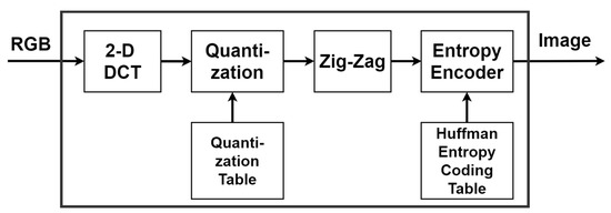
Figure 1.
Flow chart of the standard image compression technique.
To realize real-time WSN systems, many high-performance discrete cosine transform (DCT) algorithms of JPEG were proposed for VLSI implementation [28,29,30]. To reduce hardware costs, Loeffler proposed an efficient one-dimension (1-D) DCT algorithm, which utilized 11 multipliers and 29 adders only [28]. In turn, the coordinate rotation digital computer (CORDIC)-based Loeffler DCT algorithm was proposed to avoid using multipliers and to achieve a power consumption of only about 20% akin to Loeffler’s work. CORDIC is the algorithm used to evaluate sinusoidal/hyperbolic functions and can be used for intelligent robots [31,32], along with the application of communication systems and signal processing [33]. In [30], a low complexity CORDIC-DCT algorithm was proposed to implement 2-D DCT based on the row-column method by using 1-D DCT twice. In previous studies, [29,30], the efficient unfolded CORDIC-based algorithms for DCT were proposed when allowing small indispensable accuracy errors. On the other hand, the low-complexity fully parallel hardware architecture for DCT, called FPAX-CORDIC, was proposed to avoid using the memory register of the Para-CORDIC [34]. Recently, a high-performance CORDIC-based algorithm that included a square root and inverse trigonometric operator for biped robots was realized on a field-programmable-gate array (FPGA) device. A high-accuracy CORDIC-based algorithm for biped robots was proposed in [35], in which a pipeline and hardware sharing techniques were used to improve performance and reduce hardware costs efficiently.
As mentioned above, it is necessary to develop a high-performance, high-quality, and low-complexity image compression technique for image and video encoders. In this paper, an efficient, low-complexity, and high-quality hardware-oriented Loeffler DCT algorithm with recursive CORDIC architecture for image and video encoders is proposed. The remaining parts of the paper are organized as follows: In Section 2, the image compression algorithm is described. Section 3 shows the VLSI architecture for the proposed cost-efficient hardware-oriented Loeffler DCT algorithm with recursive CORDIC for image and video encoders. In Section 4, experimental results of the proposed Loeffler DCT algorithm with recursive CORDIC are demonstrated. Finally, concluding remarks are made in Section 5.
2. The Image Compression Algorithm
2.1. JPEG
JPEG is a widely used method of lossy image compression for digital data, images, and digital photos. This method discards some minor information to achieve image compression. JPEG can provide different levels of data compression by considering the tradeoff between storage space and image quality. In general, digital image pixels in neighboring regions are highly correlated with each other, and, thus, high data compression can be achieved. The image-coding algorithm is composed of data correlation reduction, value quantization, and entropy coding, as shown in Figure 1. To reduce correlation, DCT is one of the most well-known methods. After manipulating the DCT on the digital data, the resulting DCT coefficients are uniformly quantized using the quantization table. The purpose of quantization is to achieve a higher compression ratio by obtaining DCT coefficients with adequate precision, which is enough to achieve the desired image quality. JPEG [18] uses the standard quantization table in Figure 2, which is the example quantization table for luminance components.

Figure 2.
The standard quantization table for luminance components.
Entropy coding is the final step of DCT-based encoder processing. In this step, additional compression by encoding the quantized DCT coefficients can be obtained. The most widely known and the most widely used algorithm for entropy coding is the Huffman coding algorithm.
As mentioned above, most operations were focused on DCT design for hardware cost reduction.
2.2. DCT
The DCT algorithm is widely used in data/video compression, which allows unequal computation on the spatial domain data to generate the frequency–domain outputs. Some DCT computations are crucial to image quality while others are not. The two-dimensional DCT in Equation (1) transform an N × N block sample from spatial domain into frequency domain .
where normalization factors and for . The 2-D DCT has a disadvantage, that is, the hardware cost. In [28], Loeffler used only 11 multipliers to implement the 1-D DCT. The following subsection presents how the 1-D DCT is utilized to implement the 2-D DCT.
2.3. 2-D DCT Using Row-Column 1-D DCT Architecture
In this section, we adopt the row–column method based on the 1-D DCT to implement the 2-D DCT to reduce complexity. As shown in Figure 3, the row–column method applies the 1-D DCT to the image block twice. Given the image block with size N × N, the 1-D DCT is performed on the rows of , and then the 1-D DCT is performed on the columns of . Between the two 1-D DCTs is the N × N transposition memory. The matrix is defined as the orthonormal matrix of 1-D DCT with size N × N, where is the -th element of defined by
where normalization factors and for . According to the row-column method, the 2-D DCT performed on the image block is given by
where the superscript denotes the matrix transpose. In this paper, the value of N is set to eight according to the JPEG standard.

Figure 3.
The two-dimensional discrete cosine transform (2-D DCT) realized by the row–column method based on the 1-D DCT.
2.4. CORDIC Algorithm
The CORDIC algorithms for the rotation mode were summarized in [31]. Four important equations (Equations (4)–(7)) of the CORDIC algorithm are shown as follows:
where x and y denote the x-axis and y-axis components in the rectangular coordinates system, respectively; ω is the accumulated rotation angle; σ is the signum symbol; 1 or −1 defines the rotation direction; i denotes the ith iteration step; and α is the predefined angle value of each rotation step. The output data of CORDIC are amplified by a scaling factor K, which depends on the number of iteration steps. Therefore, the final values from the CORDIC algorithm have to be multiplied by 1/K. When index n in K is large enough, a constant number (1/K) will approximately be 0.60725.
2.5. Loeffler DCT Algorithm with Recursive CORDIC
Based on the work of the CORDIC-based Loeffler DCT [29], a novel Loeffler DCT algorithm with recursive CORDIC is proposed in this study. The proposed architecture of the 8-point Loeffler DCT algorithm with iterative CORDIC is shown in Figure 4. The improvement of this work over the previous algorithms lies in its four features. First, the quality of image compression is improved without using any further approximation and ignoring iteration compensation on the CORDIC algorithm. Second, recursive architecture is applied to the proposed CORDIC algorithm to reduce complexity. Third, the algorithm in [29] is optimized as illustrated in Figure 4, highlighted with a red box, where the pipeline structure for a hardware-sharing machine for the VLSI implementation is applied to reduce hardware costs. Fourth, the hardware-sharing machine technique is also applied to the three scale-factor circuits.
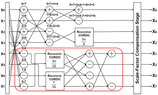
Figure 4.
Flow graph of the Loeffler DCT with recursive coordinate rotation digital computer (CORDIC).
3. VLSI Architecture
Figure 5 illustrates the VLSI architecture of the proposed 2-D DCT design. According to the row–column method, it only contains a 1-D DCT hardware-sharing machine and a transposition memory to implement a 2-D DCT. The transposition memory requires 64 12-bits to temporarily store the 1-D DCT coefficients.
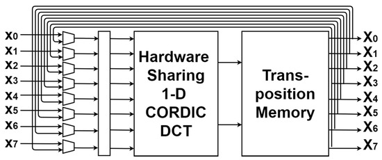
Figure 5.
The architecture of a 2-D DCT is realized by a hardware-sharing machine 1-D DCT.
Figure 6 depicts the VLSI architecture of the proposed 9-stage pipeline 1-D DCT circuit, where a hardware-sharing machine is applied to reduce hardware costs. A 1-D CORDIC DCT in the proposed design contains four hardware-sharing machines and 20 adders. The proposed design is implemented by 9-stage pipeline architecture to increase the operating frequency. It is used to calculate eight DCT coefficients given in (2).

Figure 6.
Very large scale integration (VLSI) architecture of the proposed 9-stage pipeline 1-D DCT circuit.
Table 1 lists an efficient and high precision way to develop a scaling factor generator. The design only used adders and shifters, as many as possible, to replace multipliers and dividers. Moreover, this paper utilized a hardware-sharing machine to decrease hardware complexity. Using hardware-sharing machines might somewhat increase the executing cycles. To tackle this problem, in the proposed design, a fully pipelined architecture was developed to increase throughput and reduce cycle time. The third row (scale factor = ) in Table 1 represents the 9-stage process Hardware-Sharing Scale factor_1 in Figure 6 and is shown in Figure 7. In a similar way, the fourth row (scale factor = ) in Table 1 expresses the Hardware-Sharing Scale factor_2 in Figure 6 and is shown in Figure 8. The proposed hardware-sharing scaling factors are more accurate and more cost-efficient than those of the scaling factors used in Sun et al. [29]. To conclude, the proposed scaling-factor design can provide a cost-efficient, high-precision, and high-performance structure in designing the CORDIC-based DCT.

Table 1.
Scale factors used in the work of Sun et al. [29] and in this work.
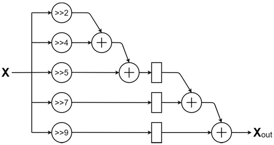
Figure 7.
The architecture of the hardware-sharing machine with scale factor_1.
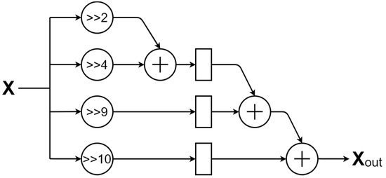
Figure 8.
The architecture of the hardware-sharing machine with scale factor_2.
The proposed CORDIC was realized by an iterative structure in a recursive CORDIC architecture, as shown in Figure 9, instead of the unfolded CORDIC architecture with an approximated scale factor. According to the experiment, the output data from CORDIC require 11 iterating cycles to be stable. This design also allows a flexible accuracy approximation where a lookup table is employed to reduce hardware area and improve performance. Users can control the iterating cycles.
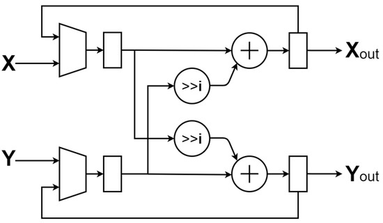
Figure 9.
The architecture of the hardware-sharing machine recursive CORDIC.
The hardware-sharing machine recursive CORDIC was realized by an iterative architecture, as shown in Figure 9. Figure 10 is the hardware-sharing CORDIC scaling factor generator, which only uses adders and shifters. With the increase in the iterating cycles, K ≈ 0.60725, this architecture is realized as illustrated in Figure 10. In addition, pipeline and operation simplification techniques were used to improve the executing performance and reduce hardware costs further.
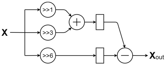
Figure 10.
The architecture of the hardware-sharing machine CORDIC scale factor.
The proposed design was composed of adders and shifters only and realized by 9-stage pipeline architecture, which can enhance the performance and reduce the hardware costs efficiently. Table 2 lists the rotation direction σ (sign-bits) of the angle at the ith stage for the CORDIC-DCT. Figure 9 and Figure 10 show the architecture of the proposed hardware-sharing machine, where Equations (4)–(7) can be realized by using only adders, shifters, and Table 2 for VLSI implementation.

Table 2.
Iteration (i) and rotation direction (σ) for the CORDIC-DCT.
4. Experimental Results of the Proposed Loeffler DCT Algorithm with Recursive CORDIC
In this section, the experimental results are evaluated for the peak signal–noise ratio (PSNR) of the proposed Loeffler DCT algorithm with recursive CORDIC. The PSNR of the three layers (R-G-B) 256-color image with size H-by-V is defined as
where Iu is the original image in the uth layer, and Ku is the reconstructed image in the uth layer for u ∈ {R,G,B} corresponding to the colors red, green, and blue, respectively. Moreover, the image size of each image in Table 1 is 512 × 512 pixels in which each pixel is 24-bits. The image size of each image in Table 2 is 768 × 512 pixels in which each pixel is 24-bits. Taking the image compression of Table 1 for example, the procedure of obtaining the reconstructed image Ku is conducted by following these four steps: (1) the original images are divided into the 4096 8 × 8 image sub-blocks; (2) the value of each pixel in the image is shifted to [−128,127] from [0,255] to reduce the dynamic range requirements of the 2-D DCT; (3) after performing the 2-D DCT and quantization matrix on the shifted-version image block, the 2-D frequency contents for the image data are obtained, in which high-frequency components are relatively small or equal to zero; (4) the reconstructed image is obtained by using the opposite operations of the above first three steps, steps (1)–(3).
In the above procedure, the luminance quantization matrix recommended by the JPEG standard was used to evaluate the value of PSNR in the image compression. Moreover, the number of CORDIC iterations in the proposed design was defined to attain the average PSNR of Loeffler DCT work [28] within 0.01 dB performance loss.
In the following experimental results, the image compression algorithm was conducted, and the image quality and compression ratio were computed to evaluate the performance of the proposed image compression algorithm. The same image datasets from previous work [28,29,30] are used in this work for PSNR comparison and are shown in Figure 11 and Figure 12. Table 3 and Table 4 list the obtained PSNR values using the different image datasets. In addition, Table 5 lists the comparison results of the computing resources for the three aforementioned landmark DCT algorithms.

Figure 11.
Eight images used for the PSNR comparison in Table 3.

Figure 12.
24 images used for the PSNR comparison in Table 4.

Table 3.
Peak signal–noise ratio (PSNR) (dB) comparison of previous DCT algorithms and this work using the first image dataset shown in Figure 11.

Table 4.
PSNR (dB) comparison of previous DCT algorithms and this work using the second image dataset shown in Figure 12.

Table 5.
Comparison of computing resources of previous DCT algorithms and this work showing the multiply, add, and shift operations.
In Table 5, the computing resources of 2-D DCT were evaluated by doubling the computing resources needed for 1-D DCT. Moreover, the required resources of the scale-factor of the CORDIC and the normalization factor of the 1-D DCT were also included for fair comparison of consistency following the work of Lee et al., which counted the resources of the two types of factors [30]. Thus, the required resources of scale factors used in the work of Sun et al. [29] and this work are listed in Table 1. Moreover, the complexity of the shifter and the complexity of the adder are assumed to be the same.
From Table 5, two observations are made. First, this work without a hardware-sharing machine achieves the lowest computing complexity. Second, this work with a hardware-sharing machine can significantly reduce the computing complexity. The lookup tables (LUTs) used for different rotation angles are listed in Table 2. According to Table 3, Table 4 and Table 5, the proposed work exhibits a high-quality and low-complexity hardware-oriented 2-D DCT algorithm for VLSI implementation. Finally, Table 6 compares the image quality between previous DCT algorithms and this work. It can be observed from Table 6 that the proposed novel recursive Loeffler DCT algorithm can achieve almost the same image quality as the original image. The two testing images, Lena and Kodak03, were widely applied to the image processing realm.

Table 6.
Image and PSNR comparisons between previous DCT algorithms and this work.
The 24 images from the Kodak dataset were used to run the image processing, including the 2-D DCT based on the proposed design, quantization (quantized with the standard quantization table), zig-zag coding, and Huffman entropy coding. At the end of processing the 24 images, the compression ratio was obtained with a value of 9.86. Significant comparisons of the previously proposed designs and this work of 2-D DCT VLSI design are listed in Table 7. The synthesized gate counts of [29,30,36,37] and for this work are 27.3 k, 22.4 k, 24.6 k, 31.5 k and 8.04 k, respectively. These were obtained from the results of [30], excluding the memory. The synthesized gate count for this work is 8.04 k, while the core area of the proposed design is 75,100 μm2. Compared with previous works, the proposed design in this study achieved a 64.1% gate count reduction. Moreover, its operating frequency and power consumption are 100 MHz and 4.17 mW, respectively. Thus, the proposed design can save at least 22.5% power compared to that of the previous designs.

Table 7.
Comparison of previous DCT algorithms and this work, where the unit is dB.
The proposed image algorithm has significant improvements with low complexity, lower memory required, low hardware costs, and reduced power consumption. Moreover, the resulting image quality of the proposed algorithm is better than that of previous works [29,30,36,37]. Considering the combined effect of the PSNR, compression ratio (CR), and gate counts, a figure of merit (FOM) is introduced and defined as
The FOM of this work is 38.68, where the Huffman entropy coding with the CR of 9.86 is employed. To fairly evaluate the FOMs of previous works, the same entropy coding and the same CR are used in Table 7. From Table 7, it can be observed that the FOM of this work is superior to those of previous works. Finally, given the improvements of this design, including low costs, high compression ratios, low power consumption, low memory requirements, and high performance, the design is appropriate for WSN and IoT applications.
5. Conclusions
This paper proposed a new hardware-oriented VLSI design with low costs and reduced memory requirements. A high accuracy 2-D DCT spectral analyzer with a hardware-sharing recursive Loeffler CORDIC and novel scaling-factor generation were developed. Compared with the previous DCT algorithm, the proposed algorithm has the benefits of high-quality and low computing resources for VLSI implementation. Moreover, with its characteristics of low memory requirements, low complexity, and high image quality, the proposed design is suitable for wireless sensor networks and IoT applications.
Author Contributions
Conceptualization, P.A.R.A.; Data curation, R.-L.C. and C.-W.C.; Formal analysis, C.-W.C.; Funding acquisition, S.-L.C.; Methodology, R.-L.C.; Project administration, C.-A.C.; Resources, S.-L.C.; Supervision, R.-L.C.; Validation, C.-W.C.; Writing—original draft, R.-L.C.; Writing—review & editing, C.-A.C. and P.A.R.A. All authors have read and agreed to the published version of the manuscript.
Funding
This work was supported by the Ministry of Science and Technology (MOST), Taiwan, under Grant numbers MOST-108-2628-E-033 -001-MY3, MOST-108-2622-E-033 -012-CC2, MOST-109-2622-E-131 -001 -CC3, and MOST-109-2221-E-131 -025, and by the National Chip Implementation Center, Taiwan.
Acknowledgments
This work was supported by the Ministry of Science and Technology (MOST), Taiwan, under Grant numbers MOST-108-2628-E-033 -001-MY3, MOST-108-2622-E-033 -012-CC2, MOST-109-2622-E-131 -001 -CC3, and MOST-109-2221-E-131 -025, and by the National Chip Implementation Center, Taiwan.
Conflicts of Interest
The authors declare no conflict of interest.
References
- Xu, K.; Qu, Y.; Yang, K. A tutorial on the internet of things: From a heterogeneous network integration perspective. IEEE Network 2016, 30, 102–108. [Google Scholar] [CrossRef]
- Movassaghi, S.; Abolhasan, M.; Lipman, J.; Smith, D.; Jamalipour, A. Wireless body area networks: A survey. IEEE Commun. Surv. Tutor. 2014, 16, 1658–1686. [Google Scholar] [CrossRef]
- Khan, I.; Belqasmi, F.; Glitho, R.; Crespi, N.; Morrow, M.; Polakos, P. Wireless sensor network virtualization: A survey. IEEE Commun. Surv. Tutor. 2016, 18, 553–576. [Google Scholar] [CrossRef]
- Misra, S.; Reisslein, M.; Xue, G. A survey of multimedia streaming in wireless sensor networks. IEEE Commun. Surv. Tutor. 2008, 10, 18–39. [Google Scholar] [CrossRef]
- Noel, A.B.; Abdaoui, A.; Elfouly, T.; Ahmed, M.H.; Badawy, A.; Shehata, M.S. Structural health monitoring using wireless sensor networks: A comprehensive survey. IEEE Commun. Surv. Tutor. 2017, 19, 1403–1423. [Google Scholar] [CrossRef]
- Goldstein, P. Ericsson Backs Away from Expectation of 50B Connected Devices by 2020, Now Sees 26B. Available online: https://www.fiercewireless.com/wireless/ericsson-backs-away-from-expectation-50b-connected-devices-by-2020-now-sees-26b (accessed on 3 June 2015).
- Kobo, H.I.; Abu-Mahfouz, A.M.; Hancke, G.P. A survey on software-defined wireless sensor networks: Challenges and design requirements. IEEE Access 2017, 5, 1872–1899. [Google Scholar] [CrossRef]
- Chen, C.-A.; Wu, C.; Abu, P.A.R.; Chen, S.-L. VLSI implementation of an efficient lossless EEG compression design for wireless body area network. Appl. Sci. 2018, 8, 1474. [Google Scholar] [CrossRef]
- Chiang, W.-Y.; Ku, C.-H.; Chen, C.-A.; Wang, L.-Y.; Abu, P.A.R.; Rao, P.-Z.; Liu, C.-K.; Liao, C.-H.; Chen, S.-L. A power-efficient multiband planar USB dongle antenna for wireless sensor networks. Sensors 2019, 19, 2568. [Google Scholar] [CrossRef] [PubMed]
- Chen, S.-L.; Chi, T.-K.; Tuan, M.-C.; Chen, C.-A.; Wang, L.-H.; Chiang, W.-Y.; Lin, M.-Y.; Abu, P.A.R. A novel low-power synchronous preamble data line chip design for oscillator control interface. Electronics 2020, 9, 1–16. [Google Scholar]
- Zhou, L.; Chao, H.-C. Multimedia traffic security architecture for the internet of things. IEEE Network 2011, 25, 35–40. [Google Scholar] [CrossRef]
- Mekonnen, T.; Porambage, P.; Harjula, E.; Ylianttila, M. Energy consumption analysis of high quality multi-tier wireless multimedia sensor network. IEEE Access 2017, 5, 15848–15858. [Google Scholar] [CrossRef]
- Aurangzeb, K.; Alhussein, M.; O’Nils, M. Analysis of binary image coding methods for outdoor applications of wireless vision sensor networks. IEEE Access 2018, 6, 16932–16941. [Google Scholar] [CrossRef]
- Chen, S.-L.; Liu, T.-Y.; Shen, C.-W.; Tuan, M.-C. VLSI implementation of a cost-efficient near- lossless CFA image compressor for wireless capsule endoscopy. IEEE Access 2016, 4, 10235–10245. [Google Scholar] [CrossRef]
- Kougianos, E.; Mohanty, S.P.; Coelho, G.; Albalawi, U.; Sundaravadivel, P. Design of a high-performance system for secure image communication in the internet of things. IEEE Access 2016, 4, 1222–1242. [Google Scholar] [CrossRef]
- Alletto, S.; Cucchiara, R.; Fiore, G.D.; Mainetti, L.; Mighali, V.; Patrono, L.; Serra, G. An indoor location-aware system for an IoT-based smart museum. IEEE Internet Things J. 2016, 3, 244–253. [Google Scholar] [CrossRef]
- Schwager, M.; Julian, B.J.; Angermann, M.; Rus, D. Eyes in the sky: Decentralized control for the deployment of robotic camera networks. Proc. IEEE 2011, 99, 1541–1561. [Google Scholar] [CrossRef]
- Pennebaker, W.; Mitchell, J. JPEG still Image Data Compression Standard; Van Nostrand Reinhold: New York, NY, USA, 1992. [Google Scholar]
- Andrea, P.; Scavongelli, C.; Orcioni, S.; Conti, M. Performance analysis of JPEG 2000 over 802.15.4 wireless image sensor network. In Proceedings of the 8th Workshop on Intelligent Solutions in Embedded Systems, Heraklion, Greece, 8–9 July 2010; pp. 55–60. [Google Scholar]
- Mohanty, S.P.; Kougianos, E.; Guturu, P. SBPG: Secure better portable graphics for trustworthy media communications in the IoT. IEEE Access 2018, 6, 5939–5953. [Google Scholar] [CrossRef]
- Cohen, A.; Nissim, N.; Elovici, Y. MalJPEG: Machine learning based solution for the detection of malicious JPEG images. IEEE Access 2020, 30, 19997–20011. [Google Scholar] [CrossRef]
- Harish, A.N.; Nissim, N.; Verma, V.; Khanna, N. Double JPEG compression detection for distinguishable blocks in images compressed with same quantization matrix. In Proceedings of the 2020 IEEE 30th International Workshop on Machine Learning for Signal Processing (MLSP), Espoo, Finland, 21–24 September 2020. [Google Scholar]
- Zeng, J.; Tan, S.; Li, B.; Huang, J. Large-scale JPEG image steganalysis using hybrid deep-learning framework. IEEE Trans. Inf. Forensics Secur. 2018, 13, 1200–1214. [Google Scholar] [CrossRef]
- Coelho, D.F.G.; Cintra, R.J.; Kulasekera, S.; Madanayake, A.; Dimitrov, V.S. Error-free computation of 8-point discrete cosine transform based on the Loeffler factorisation and algebraic integers. IET Signal Process. 2016, 10, 633–640. [Google Scholar] [CrossRef]
- Pastuszak, G. Hardware architectures for the H.265/HEVC discrete cosine transform. IET Image Process. 2015, 9, 468–477. [Google Scholar] [CrossRef]
- Kalali, E.; Mert, A.C.; Hamzaoglu, I. A computation and energy reduction technique for HEVC discrete cosine transform. IEEE Trans. Consum. Electron. 2016, 62, 166–174. [Google Scholar] [CrossRef]
- Masera, M.; Martina, M.; Masera, G. Adaptive approximated DCT architectures for HEVC. IEEE Trans. Circuits Syst. Video Technol. 2017, 27, 2714–2725. [Google Scholar] [CrossRef]
- Loeffler, C.; Lightenberg, A.; Moschytz, G.S. Practical fast 1-D DCT algorithms with 11-multiplications. In Proceedings of the 1989 International Conference on Acoustics, Speech, and Signal Processing, Glasgow, UK, 23–26 May 1989; pp. 988–991. [Google Scholar]
- Sun, C.-C.; Ruan, S.-J.; Heyne, B.; Goetze, J. Low-power and high-quality Cordic-based Loeffler DCT for signal processing. IET Circuits Devices Syst. 2007, 1, 453–461. [Google Scholar] [CrossRef]
- Lee, M.-W.; Yoon, J.-H.; Park, J. Reconfigurable CORDIC-based low-power DCT architecture based on data priority. IEEE Trans. VLSI Systems 2014, 22, 1060–1068. [Google Scholar]
- Meher, P.K.; Valls, J.; Juang, T.-B.; Sridharan, K.; Maharatna, K. 50 years of CORDIC: Algorithms, architectures, and applications. IEEE Trans. Circuits Syst. -I 2009, 56, 1893–1907. [Google Scholar] [CrossRef]
- Volder, J.E. The CORDIC Trigonometric Computing Technique. IRE Trans. Electron. Comput. 1959, EC-8, 330–334. [Google Scholar] [CrossRef]
- Aggarwal, S.; Meher, P.K.; Khare, K. Concept, design, and implementation of reconfigurable CORDIC. IEEE Trans. Very Large Scale Integr. (VLSI) Syst. 2016, 24, 1588–1592. [Google Scholar] [CrossRef]
- Chen, L.; Han, J.; Liu, W.; Lombardi, F. Algorithm and Design of a Fully Parallel Approximate Coordinate Rotation Digital Computer (CORDIC). IEEE Trans. on Multi-Scale Comput. Syst. 2017, 3, 139–151. [Google Scholar] [CrossRef]
- Chung, R.-L.; Zhang, Y.-Q.; Chen, S.-L. Fully pipelined CORDIC-based inverse kinematics FPGA design for biped robots. Electron. Lett. 2015, 51, 1241–1243. [Google Scholar] [CrossRef]
- Kim, B.; Ziavras, S.G. Low-power multiplierless DCT for image/video coders. In Proceedings of the 2009 IEEE 13th International Symposium on Consumer Electronics, Kyoto, Japan, 25–28 May 2009; pp. 133–136. [Google Scholar]
- Wu, Z.; Sha, J.; Wang, Z.; Li, L. An improved scaled DCT architecture. IEEE Trans. Consum. Electron. 2009, 55, 685–689. [Google Scholar] [CrossRef]
Publisher’s Note: MDPI stays neutral with regard to jurisdictional claims in published maps and institutional affiliations. |
© 2021 by the authors. Licensee MDPI, Basel, Switzerland. This article is an open access article distributed under the terms and conditions of the Creative Commons Attribution (CC BY) license (https://creativecommons.org/licenses/by/4.0/).


