Article

An Intelligent Algorithm for Decision Making System and Control of the GEMMA Guide Paradigm Using the Fuzzy Petri Nets Approach

by
Oz Yakrangi
1,*,
Roque J. Saltarén Pazmiño
1,
Juan S. Cely
1,
Alejandro Rodríguez
1,
Cecilia E. García Cena
1,
Pablo San Segundo Carrillo
1,
Julio De La Cueva
2 and
Amir Shapiro
3
1
Centro de Automàtica y Robótica, Escuela Técnica de Ingenieros Industriales, Universidad Politécnica de Madrid, 28006 Madrid, Spain
2
Puertos del Estado, 28042 Madrid, Spain
3
Robotics Laboratory, Department of Mechanical Engineering, Ben-Gurion University of the Negev, Beer Sheva 84105, Israel
*
Author to whom correspondence should be addressed.
Electronics 2021, 10(4), 489; https://doi.org/10.3390/electronics10040489
Submission received: 25 January 2021 / Revised: 14 February 2021 / Accepted: 15 February 2021 / Published: 19 February 2021
(This article belongs to the Section Systems & Control Engineering)

Abstract

:
The aim of this article is to present the fuzzy Petri net algorithm and its implementation on the Guide d’etude des modes de marche et d’arrêt (GEMMA) guide paradigm. Additionally, this article presents a brief description of the GEMMA guide paradigm, the fuzzy logic approach, the Petri nets theory, and fuzzy Petri nets. Each algorithm is intended for a specific set of transitions, depending on their essential conditions. All these algorithms generate intelligent and safe control of the GEMMA guide paradigm in order to have the best control system for the machine. Moreover, the algorithms are able to make the best decision automatically depending on the machine’s situation and condition, something that allows the machine to be placed in the appropriate mode for each situation. The results show that the different fuzzy Petri net algorithms were working properly for the GEMMA guide paradigm and provided a proper solution for the automation of production systems.

1. Introduction

The Guide d’etude des modes de marche et d’arrêt (GEMMA) guide paradigm was born in order to develop a tool that facilitated the automation of production systems. It was developed in 1984 by the Agence Nationale pour le Developpement de la Production Automatisée (ADEPA) in France [1]. The GEMMA is presented as a block diagram that is typified by different states and the possible conditions of the evolution between them. An important problem when dealing with the automation of a process is to correctly define what the different working modes will be and what each of them will do. The GEMMA paradigm allows for the reviewing different operating modes that may or may not be developed, and it is very useful for analyzing the stages. Since it provides a pattern that includes all the possible modes of operation, it is possible to choose the modes that meet the needs as part of the functional specifications [2]. The use of the GEMMA guide paradigm combines the communication between the operator and the system, and it avoids the misunderstandings that can appear between them. In other words, it helps avoid the delay and failure of a project that may occur due to bad communication [3].
Nowadays, mathematical models are very important in the real world and, especially for science and engineering, there are many mathematical models that are applied to program the knowledge of experts (e.g., neural networks, semantic networks, machine learning, and Petri nets). These different models provide intelligence support systems for decision-making [4].
Fuzzy logic-based control was developed in order to help the human operator or replace him. Proportional logic is used in fuzzy logic, and it is a very effective method for real-time decision-making and for control applications. This method requires an additional structure in order to conjunct or disjunct the rule of the condition. Normally, these methods work rapidly and automatically without human intervention. For this reason, they are able to serve as a very good solution for real-time control systems. The Petri net mathematical model is very expressive and may be adapted to a more intelligent model by combining it with the fuzzy reasoning model and its propositional logic [4].
Fuzzy Petri nets are graphical models with a truth degree and parallel structure that were proven to be very effective and have a significant ability to represent and reason the decision-making of systems. Fuzzy Petri nets are able to transform the vectors of a fuzzy truth state with fuzzy rules to the Petri net model. This provides a new model that is reminiscent of neural networks. The changes that have been made to traditional Petri nets allow the Petri nets to work with fuzzy logic rules and make logical reasoning for the system [5].

1.1. Contribution

In this article, a new fuzzy Petri net algorithm for the GEMMA guide paradigm is presented. The development of each algorithm was based on fuzzy Petri net rules and the conditions of the different states of the GEMMA paradigm. The main contribution of this article validates the developed algorithms for GEMMA transitioning between its different modes. It is expected that these algorithms would have a very significant impact on the control systems of industrial processes in the near future.

1.2. Outline

In order to clarify the article, it was decided to divide it into four additional sections, besides this introductory section. The second section describes the GEMMA guide paradigm and its structure. The third section presents the fuzzy Petri net approach, including its mathematical rules and an example that illustrates and verifies the approach. The fourth section describes the fuzzy Petri net algorithms for the GEMMA guide and reports the empirical validation. Finally, the last section presents the conclusion of the obtained results and future work.

2. GEMMA Guide Paradigm

2.1. Theory of GEMMA

The automation of machines and industrial processes must consider all possible states that either the machine or the process can be found in, including normal operation, failure situations, emergency stop and reset and start-up processes, as well as the different verifications and test modes. The automation program must give priority for detecting the possible failures in the operating part and performing the emergency stop process while a failure occurs. In addition, a very important issue is returning the machine to normal production when possible, considering the case that the production must continue. However, when it is not possible to continue, the process must be restarted. Each automaton program must consider such cases, with the aim of reducing the machine’s downtime to a minimum. Moreover, they must also simplify the restart process and changes in the operating mode (e.g., changing the system from manual control to automatic control) [1].
The GEMMA guide paradigm provides a very organized way to develop automation modes. For this reason, the following automation modes must be implemented:
  • Normal production;
  • Verification mode (provides manual control of the machine);
  • Test mode;
  • Initial stop state (places the machine in its initial state);
  • Failure procedure (management of the emergency stop);
  • Stop procedure (management of stopping and resetting the machine).
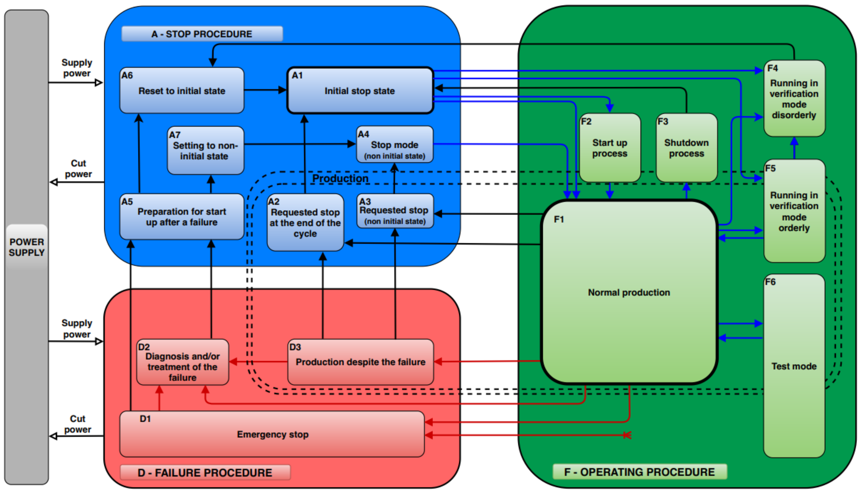
The GEMMA guide paradigm is a guide for studying the running and stop modes. It is a very well-organized representation of the different modes and states that can be found in an automated production process. It also adequately represents the transitions that occur between the states. These states are organized into three main groups as follows:
  • Stop procedure (A): This procedure includes various shutdown processes that are activated at the request of the operator for different reasons. One of them is a shutdown that is requested at the end of the cycle, and another one is a requested shutdown in a certain state of the machine. It also includes the start-up process of the machine to place the system in its initial state;
  • Operating procedure (F): This procedure indicates the necessary processes of production in order to produce the products. In addition to the normal production mode, it also includes the start-up and shut down processes for the initial state and the different verification and test modes.
  • Failure procedure (D): This procedure includes the failure processes that are activated by a failure of the machine or at the request of the operator when the emergency button is pressed.
The production procedure is described by a rectangle that contains all the possible production modes. It can be the production procedure for both the operating process and start-up process. This group also contains all the operating modes in which the system is stopped, as well as the modes that lead to stopping the system and that allow the system to move from the fault state to the stop state in order to restart the system. These processes are normally carried out at the request of the operator [1,2,3].
Figure 1 describes the GEMMA guide paradigm with its different states, which were explained earlier.

2.2. The Structure of GEMMA

In each group of the GEMMA, there are a few modes that can be activated in a certain situation [1,2,3]. The different modes and their descriptions are as follows.
The stop procedures include the following:
  • A1 – Stop in the initial state: This is the base (and first) mode of the machine. It is represented by a double rectangle. Normally, the machine is represented in this mode;
  • A2 – Requested stop at the end of the cycle: This is a temporal mode of the machine, and the machine arrives at this mode from F1 (normal production). It must be activated until the end of the cycle and then deactivated the moment it passes to the initial state mode. This mode is able to memorize the stop point that has been requested by the operator until the machine finishes performing the cycle then moves to the initial stop state mode;
  • A3 – Requested stop (non-initial state): This mode memorizes the requested stop by the operator, and the machine stops in an intermediate state of the cycle before moving to its stop mode (non-initial state).
  • A4 – Stop mode (non-initial state): This mode is an intermediate state of the machine cycle which is similar to the initial state. Depending on the machine, different stop modes can be implemented; it depends on the required intermediate modes of the manufacturing process. Therefore, there will be several options on the control panel, and the operator is able to make the proper request;
  • A5 – Preparation for start-up after a failure: In this mode, necessary actions must be taken in order to correct the failure or defect that led to the execution of the emergency stop. This can be performed by maintenance workers. The system is able to indicate approximately where the fault exists. Once the process is complete, the operator can choose how to restart the machine. In other words, the operator is able to decide whether to switch the machine to A6 (reset to initial state) in order to place it in the initial state or switch the machine to A7 (setting to non-initial state) in order to place the machine at the same certain state as before the failure;
  • A6 – Reset to initial state: The machine will automatically make the appropriate preparations for the initial state via the programmable logic controller;
  • A7 – Setting to non-initial state: This mode is the temporal mode of the machine. The machine arrives at this mode from A5 (preparation for start-up after a failure). In this step, the operator decides to place the machine in a different state from the initial state. This is important in cases where production must continue, but it cannot start from the beginning. Usually, in a failure case, the machine has stopped the production process in a certain place, and it cannot finish.
The operation procedures include the following:
  • F1 – Normal production: This mode indicates normal production of the machine. It is the most important state, and it is described by a thicker rectangle. The normal production mode is usually an automatic operation;
  • F2 – Start-up process: This mode automatically performs the necessary actions that should be made in order to place the machine in the normal production mode, such as heating the oven or preparing components for production;
  • F3 – Shutdown process: This mode is automatically returns the machine to its initial state after the production process has completed, and it includes tasks such as emptying or cleaning the machine;
  • F4 – Running in verification mode disorderly: The machine is placed under manual control, and the operator can control the machine manually. These movements must be carried out according to the safety conditions of the machine. This is usually used to correctly regulate the components of the machine, such as sensors, or to place the machine in a required state of the production process;
  • F5 – Running in verification mode orderly: In this mode, the machine performs the complete cycle of the operation in order. Generally, it is used in order to validate the machine’s production process;
  • F6 – Test mode: The automated control system checks for the correct operation of the machine and its components.
The failure procedures include the following:
  • D1 – Emergency stop: In this mode, the machine must be placed in a safe situation for both the operator and the product. Normally, this mode involves the rapid stopping of the entire machine. The automated control system must memorize the state of the previous mode in order to be able to place the machine at a certain place after the failure again (if necessary). In this way, the machine will be able to continue production from the exact same state where it stopped;
  • D2 – Diagnosis and/or treatment of the failure: The automated control system is able to guide the operator in order to indicate approximately where the defect is. However, the failure will be repaired by the operator or by the maintenance worker;
  • D3 – Production despite the failure: In cases where it is necessary to continue production even when the system is not working correctly, this mode can be activated if there is no danger to the operator or the machine. For example, if the operation fails and it can be fixed by an operator, or when there is a position failure of the manufacturing line but production is duplicated, it can be continued.
In Figure 1, it is possible to see the structure of the GEMMA guide paradigm, including its different states and modes.

3. Fuzzy Petri Nets

3.1. Fuzzy Logic Approach

The English meaning of the word fuzzy is blurred, confused or vague. This word implies something about the technical idea of fuzzy systems and how they work. Fuzzy systems are inaccurate systems but must be defined accurately, as well as the fuzzy control. Fuzzy logic computes the truth degree wider than the usual Boolean true or false (1 or 0) method; it includes the Boolean 0 or 1 measure, but only for the extreme cases, and it also includes various true states in between. Normally, control systems are linear, and this word defined them on a technical level. In the same way, the word fuzzy defined the fuzzy systems. Actually, despite the inaccurate presentation of the technicality of these systems, fuzzy systems are accurate systems that achieve precise control [6].
Research of fuzzy logic was first started in 1965 by Lotfi A. Zadeh, and it was discovered to be a powerful control system for different processes like industrial processs, households and the diagnosis of systems. The quick growth of these systems was found first in Japan, and then they arrived in the rest of the world. Due to the nonlinearity and changing response times of fuzzy systems, they are very useful for many fields that require complex control systems. Usually, traditional control systems are not able to provide the appropriate control for these complex applications. Surely, fuzzy logic systems must handled by an operator that has knowledge of the correct inputs and conditions in order to provide the system the possibility to understand the application in a good way and control it correctly [6].
Nowadays, distributed control systems (DCSs) are the most common in the industry. Usually, they are used to control different production lines, like those in chemical plants and pharmaceutical factories which need a continual control process. Originally, the goal of the programmable logic controller (PLC) was to replace the relay technology, and they are used for control of events such as in automotive and electronic applications. Currently, they have huge instruction books that consist of all the necessary knowledge for continuous control. However, they are still missing the appropriate instructions for intelligent control [7].
The use of fuzzy logic systems is greatly justified in control systems. Human experience and research over the years has led people to have enough knowledge in order to attain the necessary amount of control [8]. However, a human’s ability to understand the world is limited, and for this reason, a person will arrive at some situation where he does not have enough knowledge and information, especially with inaccurate information. Another human limitation is communication and how a person describes information. This may cause inaccuracy as well, as the person is not able to communicate and be as accurate as the machine. In other words, the human language is limited and vague. Human perception of the world is preventive by defined facts that provide the person understanding of the situation, such as if something is old, young, tall or short. These facts are correct and help humans understand the situation. Nevertheless, these facts are inaccurate, though for the human they are sufficient for understanding each other or a certain situation. However, they will not work for machines, and as a result, the machines will not be precise and will not be able to perform their tasks. Programming languages are very poor compared with natural languages, but they are very precise. Natural languages are not precise; they are fuzzy [9].

3.2. Fuzzy Logic for Control Systems

The use of fuzzy systems is very important for the control of many industrial processes due to their large number of advantages, such as their technology and results being very simple and able to be transported easily between the different products. Additionally, they have smooth and robust controller behavior. Moreover, their abilities are very significant, such as easily translating inaccurate human knowledge and controlling unstable systems [10].
Fuzzy systems are very successful at controlling applications. Nowadays, most of an application’s control is based on fuzzy systems (e.g., controlling the room temperature, anti-braking systems of vehicles, traffic light systems, watching machines and economic systems) [10].
While using a traditional control system, it is necessary to know the model, accurate terms and target. This may be very complicated in a lot of applications. However, while using a fuzzy system for control, it is possible to use human experience and expertise in order to design the control system. The best way to design fuzzy logic for control is applying the basic role of IF-THEN [11].
In order to design a fuzzy system for control, there are a few assumptions that have to be made. The first assumption is that for an observable and controllable application, the inputs must be considered, and the outputs need to be available in order to predict and control the target. The second assumption is assuming that there is a set of knowledge with principles and a set of input and output data that will provide these principles, in addition to assuming that a solution exists. Another assumption is that the precision range of the fuzzy system must be acceptable. Moreover, the stability and optimality of the system have to be open and not treated clearly [12].

3.3. Petri Nets

A Petri net is one of the best mathematical modeling tools for control systems, and it was found first by Carl Adam Petri in 1962. He proved that this tool is very reliable for and effective at modeling and simulating control systems [11]. A Petri net is normally used to model, control and analyze different events in a dynamic system. It is defined by the event distribution, driven process, conflicts, parallelism and asynchronous processes. Petri nets are especially used for modeling and analyzing manufacturing processes due to their accuracy and efficient analysis provided from the interaction between the events [13]. Moreover, they work logically from their knowledge of the way that the system has to work and provide the solution for certain model conflicts. In addition, they execute real-time analysis. Petri nets are used for graphically modeling and analytically testing the parallel events that occur in the system and that are surely very appropriate for modeling and analyzing a manufacturing system [14].
Petri net models graphically describe the structure of the system and its distribution. Petri nets are composed of two different nodes that are connected by directed arcs with a weight. The structure of a Petri net is very useful for showing the system and making clear how it works. A Petri net graph is constructed of circles and bars. The circles represent the places or states of the graph, and the bars represent the transitions or events. The arcs between the places and transitions of the graph represent the input and output relationship. Each arc is connected from a place (pj) to a transition (tj) and determines the place as an input of the transition. In the case of there being more the one input to a transition, there will be more than one arc, and each arc will indicate one input to the transition. The output of a place is defined by an arc that goes out from the place to the transition. In the case of there being more than one output, there will be more than one arc, similar to the inputs [15].
The normal Petri net (P/T) model is defined as a four tuple PN = (P, T, I, O), where P = (P1, P2,…,Pn) is the set of places and T = (T1, T2,…,Tn) is the set of transitions, I is the input function and O is the output function. The set of places and transitions are disjointed and presented as P ∩ T = ∅, while the the input is I ⊆ (P × T) and the output is O ⊆ (T × P). The place pj is the tj transition input for pj ∈ I(tj), and pj is the output for pj ∈ O(tj). The basic structure of a Petri net is defined by the different places, transitions, and input and output functions. The Petri structure is illustrated in Figure 2.

3.4. Fuzzy Petri Nets for Decision-Making

The fuzzy Petri net is a very useful method for a decision-making system, and it is based on the fuzzy rule of IF condition, THEN action. By this rule, when the condition consumes, the action produces. Knowledge of the decision-making system is based on the rule collection. Each transition of the fuzzy Petri net is defined as a rule that provides a change in a certain state [16].
Formally, the fuzzy Petri net is a tuple, and it is represented mathematically in the following way:
FPN = (P, T, S, I, O, α, β, λ, M0)
where
P = {p1, p2,…, pn} is the finite set of places, n > 0
T = {t1, t2,…, tm} is the finite set of transitions, m > 0
S = {s1, s2,…, sn } is the finite set of statements
The sets P, T and S are pairwise disjoint. In other words, the different sets are not comparable, and they have an empty intersection such that
P ∩ T = P ∩ S = T ∩ S = ∅
I: P→T is the input function of the directed arc from the place to the transition
O: P→T is the output function of the directed arc from the transition to the place
α: P→S is the statement binding function
β: T→[0,1] is the truth degree function
λ: T→[0,1] is the threshold function
M0: P→[0,1] is the initial marking
Firing of the transition = Enabled minM ( t j )     λ ( pj ) Disabled otherwise
The value of each truth function β(t) is located under each transition, and it defines the truth degree of the transition. If the transition is enabled to fire, the output that will be transmitted to the next step will be the multiplication of the minimum or maximum value of the inputs, depending on the transition type (minimum or maximum transition), and β(t). The fuzzy Petri net has two modes of transitions that provide a powerful method for the decision-making system. The first mode is the minimum type. This transition will provide as an output the multiplication of β(t) to the minimum value of the inputs. The second mode is the maximum transition type. This transition will provide as an output the multiplication of β(t) to the maximum value of the inputs. The transition type is indicated below the transition as a max or min, and the transition type is selected according to the operator’s needs. It is possible to see these two types of transitions mathematically in the equation below:
M ( p )   = mode 1 min ( M ( t j ) ) β ( tj ) mode 2 max ( M ( t j ) ) β ( tj )
The transitions can fire only when they are enabled. After the transition is fired, the token of the input will be removed and transmitted to the output, depending on the transition conditions. This fact is very partial to a certain transition in that it will only affect the inputs and outputs of the specific transition. In other words, the transition that fires performs a very simple action: it removes the token from the inputs and transmits them to the outputs. For this reason, the fuzzy Petri net is a mathematical tool that is able work in parallel [16].
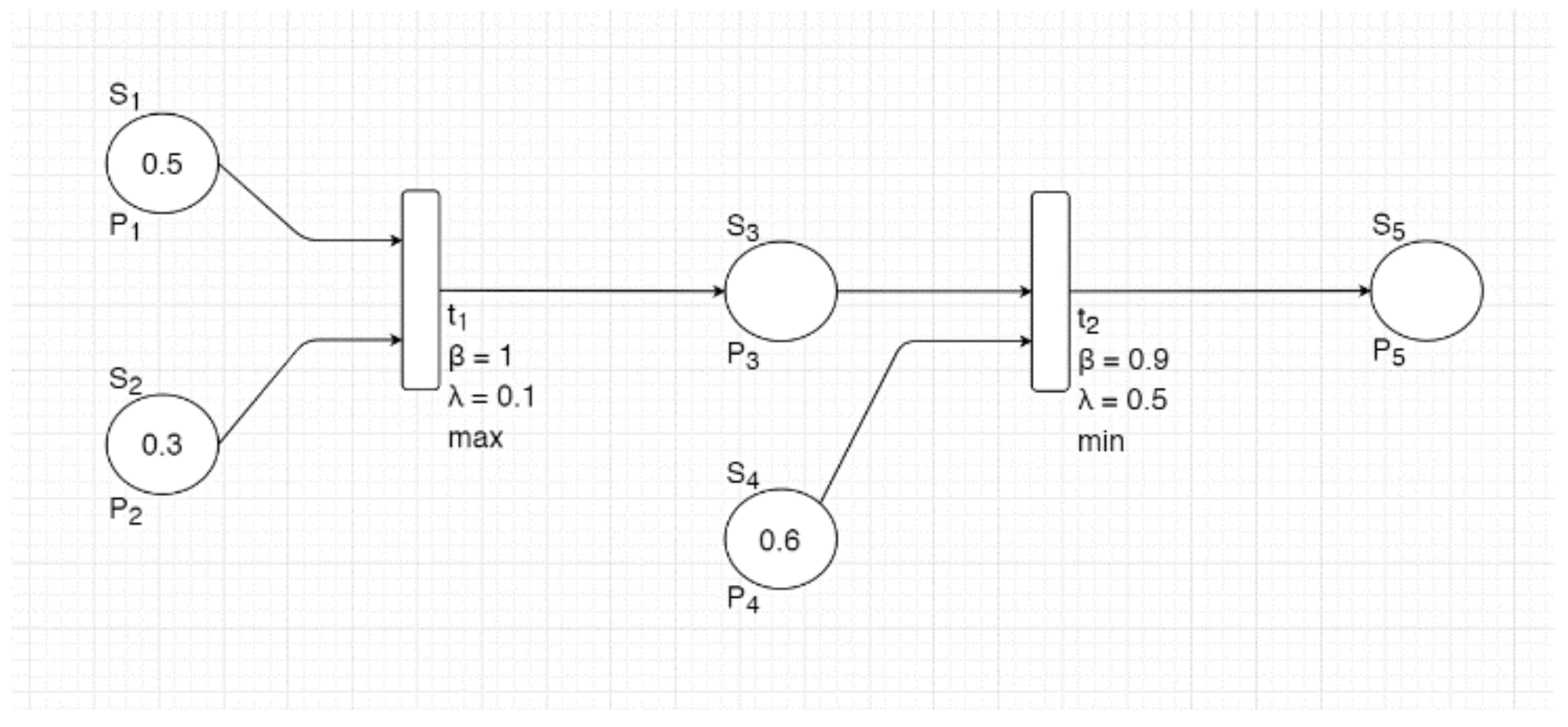
In Figure 3 below, it is possible to see an example graph of a fuzzy Petri net with the different modes of transitions, which is also a mathematical example.
FPN = (P, T, S, I, O, α, β, λ, M0)
The set of places is expressed as
P = {p1, p2, p3, p4, p5}
The transition set of the algorithm is expressed as
T = {t1, t2}
The statement set of the algorithm is expressed as
S = {s1, s2, s3, s4, s5}
The input functions of the algorithm are expressed as
I(t1) = {p1, p2}
I(t2) = {p3, p4}
The output functions of the algorithm are expressed as
O(t1) = {p3}
O(t2) = {p5}
The statement binding functions of the algorithm are expressed as
α(p1) = s1
α(p2) = s2
α(p3) = s3
α(p4) = s4
α(p5) = s5
The truth degree function of the algorithm is expressed as
β(t1) = 1
β(t2) = 0.9
The threshold function of the algorithm is expressed as
λ(t1) = 0.1
λ(t1) = 0.5
The initial marking of the algorithm is expressed as
M0 = {0.5, 0.3, ∅, 0.6, ∅}
Transition 1 (max) is expressed as
minM(t1) = 0.3
λ(t1) = 0.1
minM(t1) > λ(t1) ⟹ Enabled
M′(p3) = max(M(t1))∙β(t1) = 0.5∙1 = 0.5
Transition 2 (min) is expressed as
minM(t2) = 0.5
λ(t2) = 0.5
minM(t2) > λ(t2) ⟹ Enabled
M′(p5) = min(M(t2))∙β(t2) = 0.5∙0.9 = 0.45
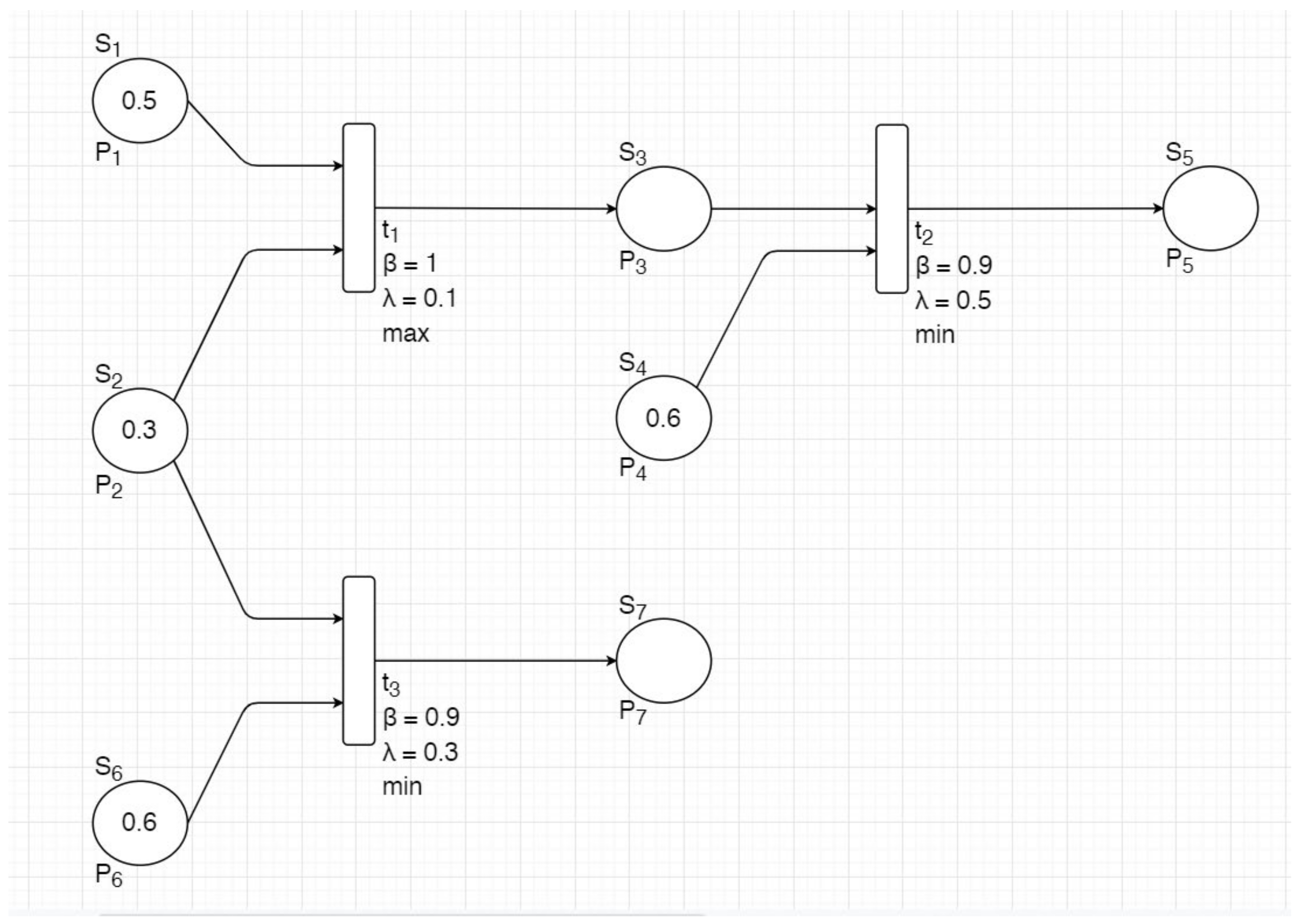
In this simple example, it is possible to graphically and mathematically see the fuzzy Petri net and how it works in an appropriate way for decision-making. It is possible to notice that transitions 1 and 2 are enabled, and the place P5 will have a value of 0.45. Moreover, the next example presents a complicated fuzzy Petri net where there are two different transitions with a mutual place, and in one of them, the minimum value of the inputs is equal to the threshold value minM(tj) = λ(pj), and the other one is greater than the threshold value minM(tj) > λ(pj). According to the fuzzy Petri net firing rule, both can be enabled, but in this case, the greater value is preferable, and only the greater one will fire, as is shown in Figure 4.
In this case, transitions 1 and 3 have a mutual input in place 2. It was possible to assume that both of the transitions would be enabled and would fire due to their conditions:
minM(t1) > λ(t1) ⟹ Enabled
minM(t3) > λ(t3) ⟹ Enabled
However, according to the fuzzy Petri net firing rule, only the greater value is preferred, and it will be the only transition that will fire. As such, in this example, transition 1 is enabled and transition 3 is disabled.

4. Fuzzy Petri Net Algorithms for the GEMMA Guide

4.1. Stop Procedure to Operation Procedure

The transition between the stop procedure A1 mode to the different operation modes (F1, F2, F4 and F5) is a critical issue for having appropriate control of the machine. While the machine is in the initial stop state (A1), it has the possibility to pass to three different modes, and due to certain requirements, this is decided by the operator. In a situation that the operator desires to place the machine in the normal production mode in order to start the production, the machine can be placed in two different modes: normal production (F1) or the start-up process (F2). The decision of the correct mode will be done automatically by the control; that is to say, while the necessary initial sensors are on, the control will place the machine in its normal production mode. However, in a case where not all of the initial sensors of the machine are on or the machine is not ready to start production due to different issues, such as machine cleaning being required, the control will place the machine in a start-up process mode in order to let the machine prepare itself for production. Moreover, when the operator desires to place the machine in either verification mode 1 (F4) or verification mode 2 (F5), he is able to do so with the control directly from the initial state (A1).
The fuzzy Petri net algorithm provides an intelligence and safe way to control the transitions of the machine. By this algorithm, the operator is able to place the machine in the mode that he desires in order to either start production or make some verifications of the machine. In Figure 5, it is possible to see the fuzzy Petri net algorithm of the transition between the initial state and the different operation modes of the GEMMA.
From Figure 5, it can be seen that this fuzzy Petri net algorithm allows the operator to choose what he desires to do next, such as placing the machine in one of the verification modes by selecting the appropriate verification mode button (1 or 2). Additionally, the operator can start production by pushing the activation mode button. In this case, the algorithm will automatically place the machine in the appropriate mode (F1 or F2) in order to start production correctly.
By applying fuzzy Petri net mathematical calculations and the rules that have been shown, the following results are obtained.
For the transition from A1 to F1 or F2, while the activation button is on, M0(p4) = 1, and when the initial sensors are off, M0(p3) = 0. As a consequence, the F2 state of the GEMMA guide is on, and the machine will be placed in the start-up process mode. Alternatively, while the activation button is on, M0(p4) = 1, and when the initial sensors are on, M0(p3) = 1. In this case, the F1 state of the GEMMA guide is on, and the machine will be placed in the normal production mode. In this case, both transition 3 and transition 4 can fire due to the fuzzy Petri net firing rule minM(tj) ≥ λpj. However, when there is a case where minM(tj) = λpj in one transition and minM(tj) > λpj in the other transition, the bigger value will be preferable, and in this case, only transition 3 will fire, and the F1 state of the GEMMA guide will be on.
For the transition from A1 to F4 or F5, while the verification mode 1 button is on, M0(p11) = 1, the F4 state of the GEMMA guide is on, and the machine will be placed in verification mode 1. Alternatively, while the verification mode 2 button is on, M0(p12) = 1, the F5 state of the GEMMA guide is on, and the machine will be placed in verification mode 2.

4.2. Operation Procedure

There are several significant transitions in the operation procedures, and these different transitions are decided by the operator, according to certain situations and requirements. In case the operator desires to make some verification of the machine at a certain point in production, he is able to make it by selecting the appropriate mode according to his needs. In other words, he can place the machine either in different verification modes (F4 or F5) or in the test mode (F6) during production. While he finishes verifying the machine, he is able to either return to production (from F5 or F6) or restart the machine to its initial state (from F4 or F5), depending on his needs.
The fuzzy Petri net algorithm for the operation procedure makes these transitions for the operator’s needs safe and prevents problems that may occur during transitions. By this algorithm, the operator is able to choose which mode to place the machine in and whether to come back to a certain point of production or restart the machine to the initial state. Figure 6 describes the fuzzy Petri net algorithm of the operation procedure, including the fuzzy Petri net places and transitions and their values.
From the figure, it is possible to notice that the operator is able to choose in which mode to place the machine in regard to his needs. For example, while the machine is placed in the normal production mode and verification button 1 or 2 is pressed, the machine will be placed in either verification mode 1 or 2, respectively. In the same way, the machine can be placed in its test mode by the test button.
Applying the fuzzy Petri net mathematical calculations and rules that have been shown yields the following results.
For the transition from F1 to F4, while the verification mode 1 button is pressed, M0(p2) = 1, the F4 state of the GEMMA is on, and the machine will be placed in verification mode 1.
For the transition from F1 to F5, while the verification mode 2 button is pressed, M0(p3) = 1, the F5 state of the GEMMA is on, and the machine will be placed in verification mode 2.
For the transition from F1 to F6, while the test button is pressed, M0(p4) = 1, the F6 state of the GEMMA is on, and the machine will be placed in test mode.

4.3. Operation Procedure to Stop Procedure

The operation procedure to stop procedure transitions are very important for the control system of the machine and to the machine’s processes. For example, this can reduce the production cost in a case where there is some error in production and some details need to be modified in order to correct production instead of throwing it away and starting over. Moreover, in a case where the operator desires to shut the machine down, he is able to do it with these transitions, and the control will place the machine in the appropriate mode automatically; that is to say, if the machine finished production correctly, the machine will be placed in the requested stop at the end of the cycle (A2). Additionally, in a case where the shutdown button is pressed and production did not finish correctly, the machine will be placed in the shutdown process (F3) in order to prepare the machine for the initial stop state.
The fuzzy Petri net algorithm for the transitions between the operation procedure to stop procedure provides intelligent and safe control. Moreover, by this algorithm, the machine will be placed in the correct mode in regard to the operator’s needs. This will allow him to stop the production and, when it is necessary, return to the same production point in order to continue or shut down the machine, either for starting over or turning off the machine. The figure below shows the fuzzy Petri net algorithm for these different transitions, including the fuzzy Petri net places and transitions and their values.
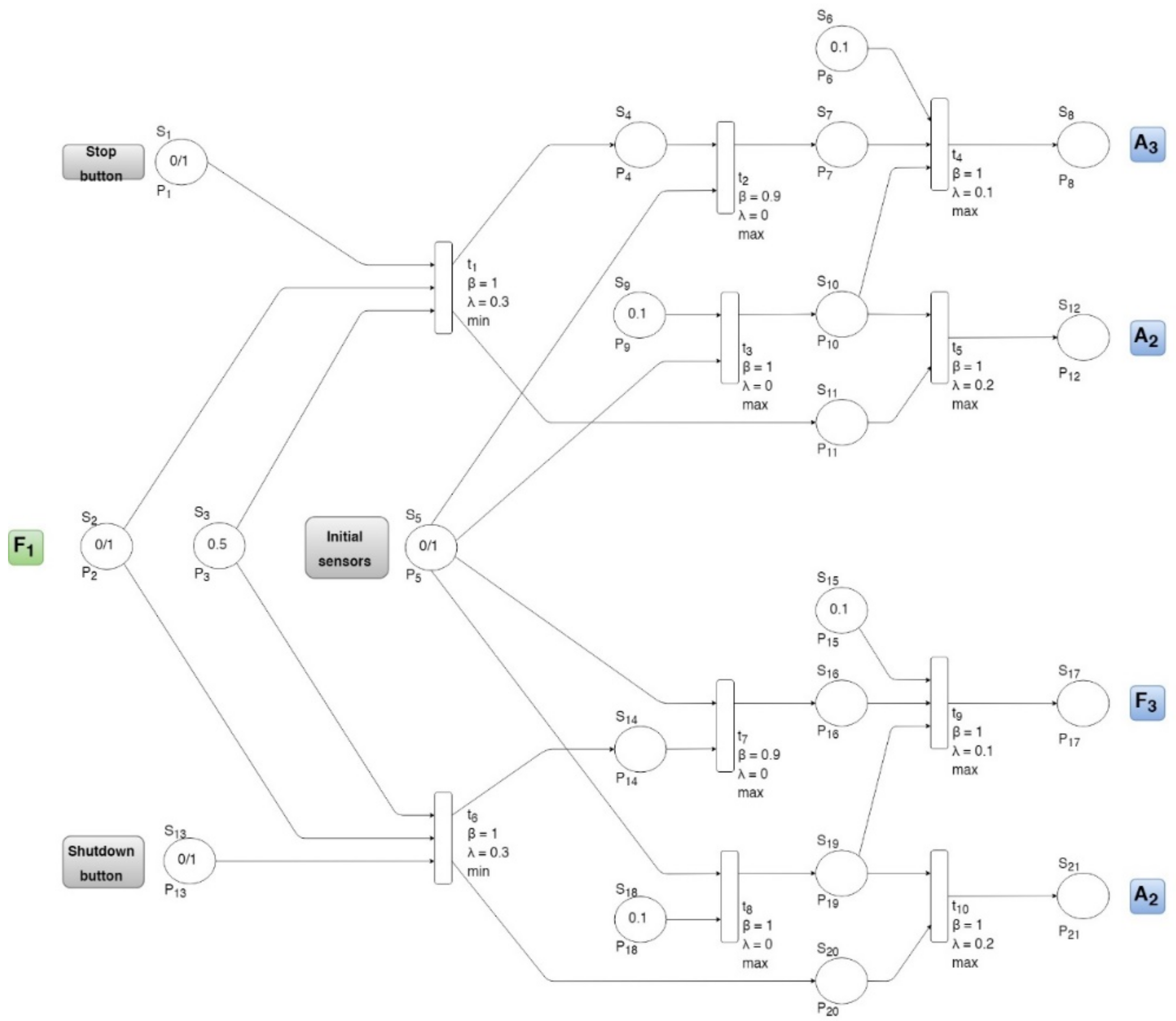
From the Figure 7, it is possible to see the different transitions of the operation procedure to the stop procedure and when they will occur. For example, when the operator desires to stop the machine, it will be placed either in the requested stop at the end of the cycle (A2) or in the requested stop (non-initial state) mode (A3) automatically, depending on the machine’s situation. In a similar way, the machine will shut down when the operator requires it. The fuzzy Petri net results for this algorithm are presented below.
For the transition from F1 to A2 or A3, while the stop button is pressed, M0(p1) = 1, the initial sensors are off, M0(p5) = 0, the A3 state of the GEMMA is on, and the machine will be placed in the requested stop (non-initial state) mode in order to allow the operator to continue production when it is needed. On the contrary, while the stop button is pressed, M0(p1) = 1, the initial sensors are on as well, M0(p5) = 1, the A2 state of GEMMA is on, and the machine will be placed in the requested stop mode at the end of the cycle in order to set the machine in the initial stop state. In this case, both transition 4 and transition 5 can fire due to the fuzzy Petri net firing rule minM(tj) ≥ λpj. However, when there is a case where minM(ti) = λpi in one transition and minM(ti) > λpj in the other transition, the bigger value will be preferable, and in this case, only transition 5 will fire, and the A2 state of the GEMMA guide will be on.
For the transition from F1 to F3 or A2, while the shutdown button is pressed, M0(p13) = 1, the initial sensors are off, M0(p5) = 0, the F3 state of the GEMMA will be on, and the machine will be placed in the shutdown process mode in order to prepare the machine for the initial stop state. On the contrary, while the shutdown button is pressed, M0(p1) = 1, the initial sensors are on as well, M0(p5) = 1, the A2 state of the GEMMA is on, and the machine will be placed in the requested stop mode at the end of the cycle in order to set the machine to the initial stop state.

4.4. Operation Procedure to Failure Procedure

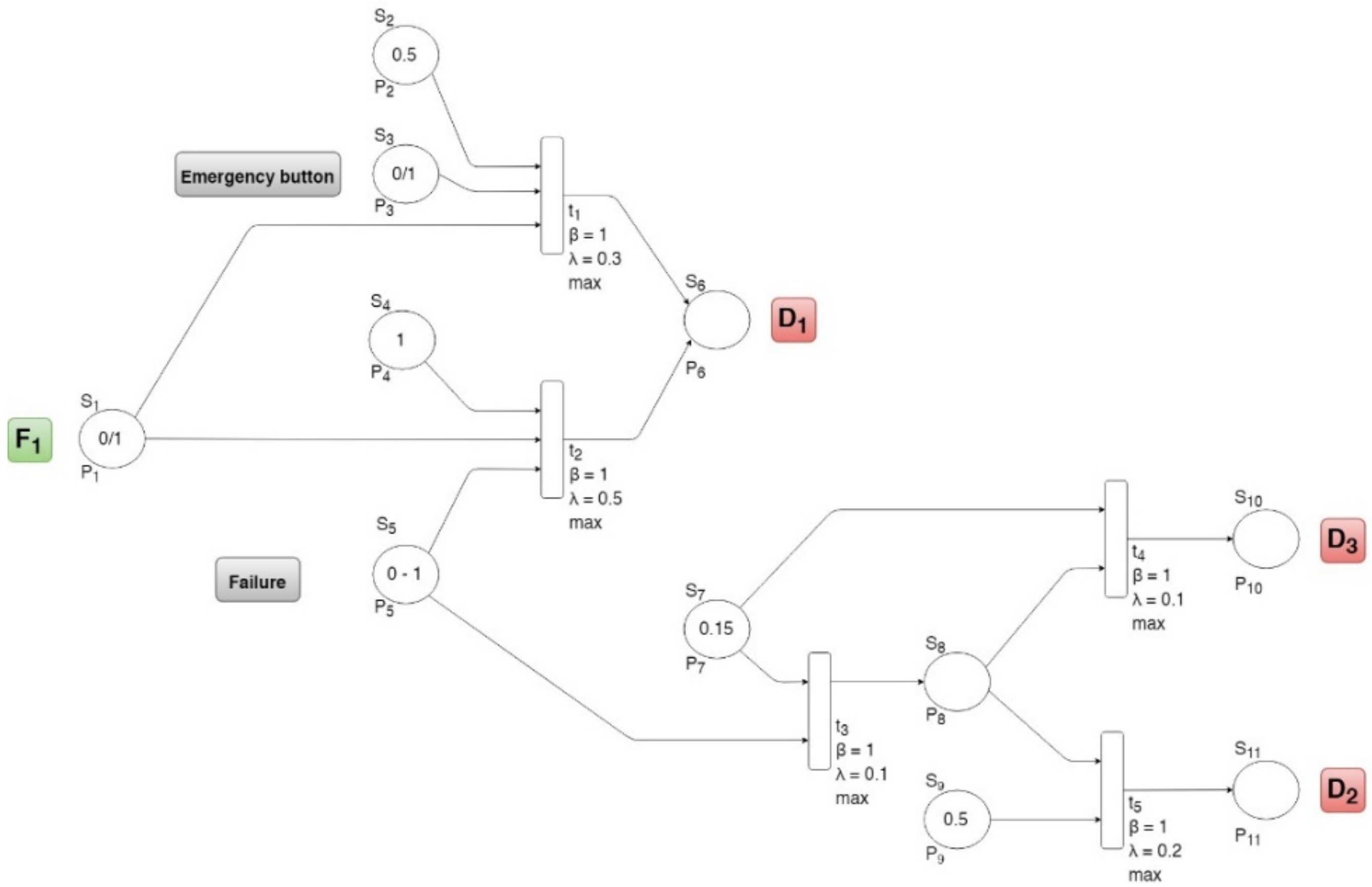
The fuzzy Petri net algorithm for moving from the operation procedure to the failure procedure ensures different failures are handled in an intelligent and safe way in order to prevent damage to the machine and danger to human life. This algorithm is divided into two important branches: the emergency button that is controlled by the operator and the different types of failures that are controlled automatically by the algorithm. The fuzzy Petri net algorithm is described in the Figure 8 below.
The algorithm divides the critical failures into three parts in order to place the machine in the appropriate failure mode (D1, D2 or D3). The critical failure value ranges from zero to one. As long as its value equals zero, the machine is working properly. While the failure is not very critical, the machine can continue production while the failure exists. If its value is greater than 0 and less than or equal to 0.2 (0 < failure ≤ 0.2), the algorithm will stop the machine automatically and place it in production, despite the failure mode (D3). When the machine is placed in this mode, the operator can decide whether to continue production or restart the machine. The next level of failure is when its value range is greater than 0.2 and smaller than 0.6 (0.2 < failure < 0.6). This case means that the failure is more critical, and the machine cannot continue production. In this case, the machine will be placed in diagnosis or treatment of the failure mode (D2) in order to detect where the failure occurred and repair it. Once the failure is fixed, the operator is able to restart the machine to the initial stop state. The last and most critical level is when the critical failure value is greater than 0.5 and less than or equal to 1 (0.5 < failure ≤ 1). When this level of failure occurs, the algorithm stops the machine immediately and places it in the emergency stop mode (D1) in order to detect the failure and repair it. These different failure levels are set specially for each machine in the control programming stage, and they depend on its conditions. The results of this algorithm clarify the different levels of failure and the algorithm reaction for each one.
For the transition from F1 to D1, while either the emergency button is pressed (M0(p3) = 1) or the failure value is bigger than 0.5 (M0(p5) > 0.5), the D1 state of the GEMMA is on, and the machine will be placed in the emergency stop mode in order to detect and repair the failure. Then the machine will be restarted.
While the failure value is between 0 and 0.3 (0 < M0(p5) < 0.3), the D3 state of the GEMMA is on, and the machine will be placed in production despite the failure mode in order to allow the continuation of production. On the contrary, while the failure value is greater than 0.2 and less than or equal to 0.5 (0.2 < M0(p5) ≤ 0.5), the D2 state of the GEMMA is on, and the machine will be placed in diagnosis and/or treatment of the failure mode in order to detect and repair the failure. Then, the machine will be restarted.

4.5. Failure Procedure to Stop Procedure

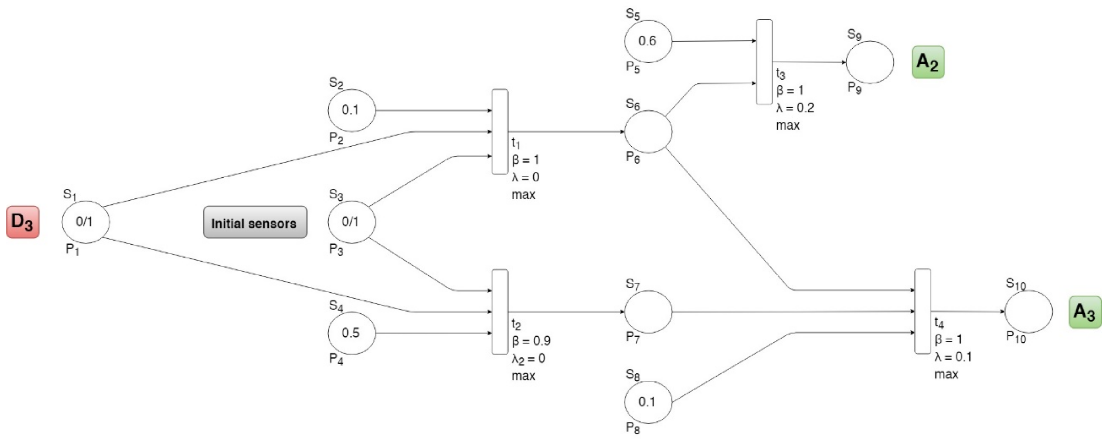
The different transitions between the failure procedure and the stop procedure allow the operator to make his decision depending on the situation. In this way, the operator is able to choose whether to continue production after the failure is repaired or restart the machine. Moreover, in a non-critical failure, production in spite of the failure is possible. The fuzzy Petri net algorithm for the transitions between the failure procedure and the stop procedure make the control both smarter and safer, and it allows for making the best decision automatically without the operator’s decision. The algorithm is presented below in Figure 9.
From the algorithm, it is possible to realize that when the machine has some medium critical failure level and is placed in the production despite the failure mode (D3), the control will place the machine automatically in the appropriate mode. In other words, the machine will be placed either in the requested stop at the end of the cycle mode (A2) or in the requested stop (non-initial state) mode (A3), depending on the situation of the machine. If the machine finishes production correctly and then the failure occurs, the machine is ready for the initial stop state. However, if the failure occurs at a certain point in production, the control allows the machine to return to the normal production mode in order to continue production. The results below clarify the transition conditions in the different situations.
While the initial sensors are off, M0(p3) = 0, the A3 state of GEMMA is on, and the machine will be placed in the requested stop (non-initial state) mode in order to allow the continuation of production. On the contrary, while the initial sensors are on, M0(p3) = 1, the A2 state of the GEMMA is on, and the machine will be placed in the requested stop mode at the end of the cycle. In this case, both transition 3 and transition 4 being able to fire due to the fuzzy Petri net firing rule minM(tj) ≥ λpj. However, when there is a case where minM(tj) = λpj in one transition and minM(tj) > λpi in the other transition, the bigger value will be preferable, and in this case, only transition 3 will fire, and the A2 state of the GEMMA guide will be on.

5. Conclusions and Future Works

The implementation of the fuzzy Petri net approach on the GEMMA guide paradigm has been proven successfully, and it provides an intelligent and safe control system. The approach for the control system looks promising with regard to production process control and solving problems that may occur during production.
The results of the stop procedure to the operation procedure show that when the activation button is on, the control system places the machine automatically in the appropriate mode in regard to the machine’s conditions. That is to say, if the machine is ready to start production, it will be placed in the normal production mode (F1). On the contrary, in a case where the machine iss not ready to start, it will be placed in the start-up process mode in order to prepare the machine for production. Moreover, while the machine is placed in the initial stop state and the operator desires to start one of the verification modes (F4 or F5), the control system will place the machine in the required mode. Along the same lines, while the machine is placed in its normal production mode (F1) and the transitions to either one of the verification modes or the test mode are needed, the operation procedure algorithm allows the operator to place the machine in the required mode.
Additionally, the results of the algorithm going from the operation procedure to the stop procedure are divided into two main actions. The first one shows that while stopping the machine is needed, the control system will place the machine in the required mode, depending on the machine’s conditions. In other words, while the stop button is on, the machine will be placed automatically in either the requested stop at the end of the cycle mode (A2) or the requested stop (non-initial state) mode (A3). The best decision will be taken by the control system to either restart the machine automatically or allow the operator to return to production. The second action of this algorithm provides the ability to shut the machine down properly. While a shutdown is needed, the control system will place the machine automatically in the requested stop at the end of the cycle mode (A2) when the machine is ready for the initial stop state. On the contrary, when the shutdown process is needed, in order to prepare the machine for the initial stop state, it will be placed in the shutdown process mode (F3).
The algorithm going from the operation procedure to the failure procedure provided significant results. This algorithm is the most important in the control system due to its purpose being safety for the human and the machine. This algorithm provides two actions: stopping the machine by pressing the emergency button and stopping the machine automatically when a failure occurs. The results of this algorithm show that the control system places the machine in the appropriate mode in regard to the failure level. For instance, when a critical failure occurs in the machine, it will be placed in the emergency stop mode (D1) in order to stop the machine immediately. It works for the different failure levels in a similar fashion; the machine will be placed in the correct mode in order to deal with the failure in the best way.
The last results that were presented in this article were the results of the failure procedure to the stop procedure. It is possible to see that while the machine is placed in the production despite the failure mode (D3), once the failure has been fixed, the control system will place the machine automatically in either the requested stop at the end of the cycle mode (A2) or the requested stop (non-initial state) mode (A3), depending on the machine’s conditions. This allows the operator to either restart the machine or return to production properly after the failure has been fixed.
The intelligent fuzzy Petri net algorithm provides valid automated function for decision-making systems and the control of many machines, such as cranes installed on a quay wall to handle electric cables and provide an onshore power supply to ships at berth (OPS). Green transport has become a critical issue recently, and OPS is the only available solution to reduce the environmental impact in the port and make a difference in the quality of life of populations settled in the vicinity of ports. The Spanish National Ports Agency took this a step further and started a project for reducing pollution and noise in Spanish ports, which will lead to environmental improvement and healthier living. This project is called the OPS MASTERPLAN for the Spanish ports, and it is funded by the European Union. The OPS MASTERPLAN project includes the identification of barriers and implementation of administrative measures to facilitate OPS technology. In addition, it analyzes some pilots in various Spanish ports and includes a specific R&I (research and innovation) innovative activity, that being the design of a fully remote automated crane for OPS. Indeed, this project aims to achieve the supplying of electrical energy to ships at berth in Spanish ports, which needs electrical cables to be handled from shore to ship by means of appropriate cranes, due to the intrinsic nature of the weight of the cables and the distances involved in reaching the ship hatches.
The control of this specific kind of crane is very special, as they handle overboard connectors at the edge of the quay wall. In addition, relevant safety issues associated with high voltage currents, galvanic protection, 50 or 60 Hz frequency conversion and ship earthing affect crane operation in practice.
That said, highly required operational conditions motivated this paper’s authors to challenge a intelligent fuzzy Petri net algorithm to govern the OPS crane. Such algorithms responded successfully. Other testing environments for the use of a fuzzy Petri net algorithm, such as underwater and in swarm robotics, produced positive results. Indeed, this algorithm proved to provide good control over underwater robots while facing different decisions that it had to make during sophisticated tasks. Additionally, in the case of swarm robotics, the algorithm is able to provide good communication between robots in order to make the best decisions while working together. In conclusion, intelligent fuzzy Peri net algorithms provide very good control and a good decision support system for a wide range of robots in different fields.
Author Contributions

The authors confirm contribution to the paper as follows: study conception: O.Y., R.J.S.P., C.E.G.C., P.S.S.C., J.D.L.C.; project administration, and resources: R.J.S.P., A.S.; data collection: O.Y., J.S.C., A.R.; design and development: O.Y.; analysis and interpretation of results: O.Y., R.J.S.P.; manuscript preparation: O.Y. All authors reviewed the results and approved the final version of the manuscript.

Funding

This work was supported in part by the Spanish Goverment Organism Puertos del Estado and European Projects H2020 under the Action Masterplan for OPS in Spanish ports 2015-EU-TM-0417-S, in part under the Grant PGC2018-095939-B-I00, and the RoboCity2030-III-CM Project (Robótica aplicada a la mejora de la calidad de vida de los ciudadanos. Fase III) under Grant S2013/MIT-2748, in part by the Programas de Actividades I + D en la Comunidad de Madrid, and in part by Structural Funds of the EU.

Conflicts of Interest

The authors declare no conflict of interest.

References

  1. Rochouse, G. La pratique du GEMMA et du GRAFCET: Le passage du GEMMA au GRAFCET. J. L’Equipment Electr. Electron. 1987, 551, 19–23. [Google Scholar]
  2. Cloutier, G. Gemma, the Complementary Tool of the Grafcet; Ecole Polytechnique De Montreal, Chemin De l’Ecole Polytechnique: Montreal, QC, Canada, 1988. [Google Scholar]
  3. ADEPA. In GEMMA (Guide D’étude des Modes de Marches et D’arrêts); Agence Nationale Pour Le DEveloppment De La Production Automatisée: Paris, France, 1981.
  4. Cardoso, J.; Valette, R.; Dubois, D. Fuzzy petri net: An overview. IFAC Proc. Vol. 1996, 29, 4866–4871. [Google Scholar] [CrossRef]
  5. Pedrycz, W.; Camargo, H. Fuzzy timed petri nets. Fuzzy Sets Syst. 2013, 140, 301–330. [Google Scholar] [CrossRef]
  6. Chen, G.; Pham, T.T. Introduction to Fuzzy Systems; Chapman & Hall/CRC: Boca Raton, FL, USA, 2006. [Google Scholar]
  7. Shaw, I.S. Fuzzy Control of Industrial Systems: Theory and Applications; Springer: Berlin, Germany, 2013. [Google Scholar]
  8. Kentli, A. Studies on fuzzy logic control of electrical machines in turkish universities: An overview. Math. Comput. Appl. 2011, 16, 236–247. [Google Scholar] [CrossRef] [Green Version]
  9. Wang, L.-X. A Course in Fuzzy Systems and Control Book; Prentice Hall: Upper Saddle River, NJ, USA, 1997; pp. 1–15. [Google Scholar]
  10. Lee, C.C. Fuzzy logic in control systems: Fuzzy logic controller. IEEE Trans. Syst. Man Cybern. 1990, 20, 404–418. [Google Scholar] [CrossRef] [Green Version]
  11. Siler, W.; Ying, H. Fuzzy control theory: The linear case. Fuzzy Sets Syst. 1989, 33, 275–290. [Google Scholar] [CrossRef]
  12. Sugeno, M. Fuzzy identification of systems and its applications to modeling and control. IEEE Trans. Syst. Man Cybern. 1985, SMC−15, 116–132. [Google Scholar]
  13. Costelha, H.; Lima, P. Modelling, analysis and execution of robotic tasks using petri nets. In Proceedings of the 2007 IEEE/RSJ International Conference on Intelligent Robots and Systems, San Diego, CA, USA, 29 October–2 November 2007; pp. 1449–1454. [Google Scholar] [CrossRef]
  14. Girault, C.; Valk, R. Petri Nets for Systems Engineering; Springer: Berlin, Germany, 2003. [Google Scholar]
  15. Murillo, L.D. Redes de Petri: Modelado e implementación de algoritmos para autómatas programables. Tecnol. Marcha. 2008, 21, 102. [Google Scholar]
  16. Looney, C.G. Fuzzy petri nets for rule-based decision-making. IEEE Trans. Syst. Man Cybern. 1988, 18, 178–183. [Google Scholar] [CrossRef]
Figure 1. Guide d’etude des modes de marche et d’arrêt (GEMMA) guide paradigm with its different states and modes.
Electronics 10 00489 g001
Figure 2. Example of a Petri net.
Electronics 10 00489 g002
Figure 3. A graphical structure of a fuzzy Petri net.
Electronics 10 00489 g003
Figure 4. An example of a fuzzy Petri net with two different transitions that have a mutual place.
Electronics 10 00489 g004
Figure 5. A graphical structure of the fuzzy Petri net algorithm for the transition between the initial stop state (A1) and the different operation modes of the GEMMA.
Electronics 10 00489 g005
Figure 6. A graphical structure of the fuzzy Petri net algorithm for the transition between the normal production mode (F1) and the different verification and test modes of the GEMMA.
Electronics 10 00489 g006
Figure 7. A graphical structure of the fuzzy Petri net algorithm for the transition between the normal production mode (F1) and the different stop modes of the GEMMA.
Electronics 10 00489 g007
Figure 8. A graphical structure of the fuzzy Petri net algorithm for the transition between the normal production mode (F1) and the different failure modes of the GEMMA.
Electronics 10 00489 g008
Figure 9. A graphical structure of the fuzzy Petri net algorithm for the transition between production despite the failure (D3) and requested stop at the end of the cycle (A2) or a requested stop (non-initial state) A3 of the GEMMA paradigm.
Electronics 10 00489 g009
Publisher’s Note: MDPI stays neutral with regard to jurisdictional claims in published maps and institutional affiliations.