Abstract
In this paper, a stator inductance identification process is proposed. The process is based on a three-level neutral-point-clamped (NPC) inverter-fed induction motor (IM) drive with a standstill condition. Previously, a low-speed alternating current (AC) injection test for stator inductance identification was proposed to overcome practical problems in conventional identification methods for three-level NPC inverter-based IM drives. However, the low-speed AC injection test-based identification method has some problems if a heavy load or mechanical brake is connected, as these can forcibly bring the rotor to a standstill during parameter identification. Since this low-speed testing-based identification assumes the motor torque is considerably lower in low-speed operations, some inaccuracy is inevitable in this kind of standstill condition. In this paper, the proposed current injection speed generator is based on the previously studied low-speed test-based stator inductance identification method, but the proposed approach gives more accurate estimates under the aforementioned standstill conditions. The proposed method regulates the speed for sinusoidal low-frequency AC injection on the basis of the instantaneous reactive and air-gap active power ratio. This proposed stator inductance identification method is more accurate than conventional fixed low-frequency AC signal injection identification method for three-level NPC inverter-fed IM drive systems with a locked-rotor standstill condition. The proposed method’s accuracy and reliability were verified by simulation and experiment using an 18.5 kW induction motor.
1. Introduction
Currently, three-level neutral-point-clamped (NPC) inverters are used not only in medium voltage (MV) drives for constant torque applications (e.g., mining scraper, conveyor), but also in specific low voltage (LV) drive systems (e.g., petrochemical, hoist application) for motor protection from high dv/dt problems [1,2,3]. When it comes to the constant torque applications, and mining systems in particular, the MV drive requires high-dynamic performance to provide high starting torque. In order to achieve high-dynamic performance for this type of drive system, accurate motor parameters are required [4,5].
In recent years, many techniques have been developed for the parameter identification process to enhance their accuracy in standstill and rotational tests [6,7,8,9,10,11,12,13,14,15,16]. If a constant torque load is connected to the drive system, such as a scraper conveyor in a mining system or a hoist application with a mechanical brake, the induction motor (IM) should be at a standstill during the parameter identification. In this kind of constant torque load condition, standstill tests are more suitable for parameter identification than rotational tests since the rotational tests should be performed under no-load conditions, and it is difficult to achieve accurate motor parameters, especially stator inductances, in this case. The common standstill methods can be further divided into two categories: DC and alternating current (AC) injection methods. Standstill DC injection test-based parameter identification methods have been implemented by the authors of [6,7,8,9] using flux integration methods. However, these kinds of identification methods have several practical problems when it comes to implementation in a three-level NPC inverter. First, since the system is standstill, it requires inverter non-linearity compensation. Three-level NPC inverters have strong non-linearity, and DC-link balancing methods are also required for the process, which affects the performance of the estimation. In addition, the temperature of HV-IGBT dynamically increases because of power loss imbalance from repetitive DC injections, which may damage the system during the process [9]. Due to the aforementioned problems, AC injection methods are preferred for three-level NPC inverter applications.
AC injection methods can also be divided into single-phase and three-phase injection methods. The single-phase test-based parameter identification methods were implemented by the authors of [10,11,12]. However, in practice, this approach may affect the measurement robustness due to the reduced AC signal amplitude [11]. The authors of [13,14,15] introduced three-phase test-based methods based on online parameter identification. However, online parameter identification methods are not appropriate under locked-rotor standstill conditions, since the estimation accuracy is low in this case. The authors of [16] presented a low-speed current injection-based stator inductance identification process for MV drives for variable load torque applications. This method was also one of the three-phase AC injection methods, but it was more accurate in low-speed testing because the stator inductance was identified on the basis of the instantaneous power reaction from the injected low-frequency AC. However, the fixed low-frequency AC injection method used by the authors of [16] had less accuracy and was difficult to use in standstill conditions (i.e., constant torque load application or mechanically locked-rotor).
Therefore, this paper proposes a current injection speed generator based on the previously studied low-speed test-based stator identification method to overcome the difficulties with three-level NPC inverter-fed IM drives with standstill conditions. In the proposed method, the low-frequency angular speed is regulated during the stator inductance identification process for instantaneous reactive and active powers to have a certain ratio. By maintaining the power ratio between the active and reactive power, the accuracy of the proposed method is also maintained. Additionally, the proposed method is more suitable than a single-phase AC method for MV drive systems because it uses a three-phase AC and has no AC signal reduction problems. The proposed stator inductance identification process estimates the stator flux on the basis of the instantaneous power and current magnitude of the motor with conventional flux and a conventional current regulator. The accuracy and reliability of this method were verified by simulation and experiment using a three-level NPC inverter-fed IM drive with a standstill condition.
The structure of this paper is as follows: In Section 2, the previously studied low-speed test-based stator inductance identification method is introduced with analysis, and a look at its drawbacks under standstill conditions is provided. In Section 3, the proposed current injection speed generator, and its analysis are presented. In Section 4 and Section 5, the proposed identification method, which was verified by simulation and experiment using a three-level NPC inverter-fed IM drive with a locked-rotor standstill condition, is explained. Finally, in Section 6, the conclusions of this research are presented.
2. Conventional Low-Speed Test-Based Stator Inductance Identification Process
In the conventional low-speed rotational test [16], the stator inductance is identified under variable-load-connected conditions [16]. Since the variable load is connected to the motor, it is similar to no-load conditions because the injected sinusoidal frequency in this test is similar to the rated slip frequency. In no-load conditions, the stator flux () becomes similar to the d-axis stator flux (). Furthermore, the field current is almost equal to the current magnitude when the torque current is approximately zero in the rotating reference frame.
In order to obtain stator flux, the instantaneous reactive power can be calculated, as in Equation (1), using the output voltages and currents of the motor, and the stator current magnitude is then calculated by Equation (2).
where and are the respective output voltages and motor currents in the stationary reference frame, and are the respective output voltages and motor currents in the synchronous reference frame, and is instantaneous reactive power. Under no-load conditions, Equation (1) can be rewritten as Equation (3) for a steady state.
where and are the low-frequency angular speed and d-axis stator flux, respectively. From Equation (3), the d-axis stator flux magnitude can be calculated using Equation (4) and the low-pass filtered instantaneous reactive power.
Using the obtained stator flux from Equation (4), the stator inductance can be calculated as follows [13,16].
Using Equation (5), the block diagram of the conventional stator inductance identification method based on low-speed testing is shown in Figure 1. Since the flux regulator only controls the d-axis current reference (), the magnitude of the injected current () is controlled along with . Furthermore, since the synchronous reference frame is used for regulators for the estimation, the injected current frequency depends on the low-angular speed reference (), the value of which is recommended to be limited under the rated slip frequency of IM, or 2 Hz [16].
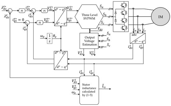
Figure 1.
Block diagram of conventional rotational test-based stator inductance identification [16].
In the conventional system [16], the injected frequency () is fixed to 2 Hz in consideration of the no-load conditions during low-speed operations. Although the stator inductance identification based on this conventional low-speed rotational test is very accurate under variable load conditions with three-level NPC inverters, the accuracy is limited under standstill conditions because only variable loads can be considered as no-load conditions with this conventional method. Therefore, the estimation accuracy of the conventional identification method is not as good for constant torque loads or for locked-rotor standstill conditions. Moreover, the stator flux is only identified on the basis of the instantaneous reactive power and fixed frequency, which adds another inaccuracy to this identification method.
Figure 2 shows the equivalent circuit of the stator inductance identification method, whose block diagram is shown in Figure 1 with a 2 Hz injection frequency. As shown in Figure 2, the magnetizing reactance is lower than the rotor resistance if the current injection speed is low enough and the slip is almost zero. However, in standstill conditions the motor slip cannot be equal to zero because real torque current would appear in the rotor. Therefore, at the fixed 2 Hz injected frequency for identification, the rotor resistance would not be high enough if we take into account the magnetizing reactance in standstill conditions. Therefore, the stator fluxes and stator inductance must also be able to be estimated on the basis of the standstill load conditions; this is the reason why the stator flux should not only be calculated on the basis of reactive power under standstill conditions. In Section 3, how to overcome the problems caused by standstill conditions in conventional low-speed testing is discussed, and the current injection speed generator is proposed.

Figure 2.
Per-phase induction motor (IM) model for inverse- equivalent circuit [16]: ( slip (s = 0), ), where is the magnetizing reactance.
3. Proposed Stator Inductance Identification Process for Standstill Conditions
In the conventional low-speed test [16], the estimated stator flux, calculated by only reactive power, is not similar to the air-gap stator flux under locked-rotor conditions. Therefore, some equations and identification processes should be modified to take this condition into account. To understand the proposed stator inductance identification process, the instantaneous power under locked-rotor conditions is analyzed, and then some modifications to the low-speed test-based identification method are proposed on the basis of this power analysis.
3.1. Instantaneous Power Analysis under Locked-Rotor Standstill Conditions
In locked-rotor standstill conditions, more power is consumed in the IM, more current is flowing on the rotor side, and the slip is equal to one, while a fixed frequency of 2 Hz is injected to the equivalent circuit, as shown in Figure 3, because the rotor resistance, which consumes air-gap active power(), becomes low.
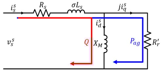
Figure 3.
Per-phase induction motor (IM) model for inverse- equivalent circuit (, slip (s = l)).
If the injection frequency is much lower than 2 Hz, the magnetizing reactance () decreases while the rotor resistance is relatively maintained, since the slip is one under constant load conditions. Eventually, the magnetizing reactance value becomes lower than before; however, this is not sufficient to ignore the rotor current in Figure 3. Therefore, when estimating the stator flux and inductance, the air-gap active power should be taken into account in this case.
In the next subsection, the conventional stator flux and inductance estimation methods are modified while taking into account both active and reactive powers.
3.2. Modification of Identification Process Considering Locked-Rotor Standstill Conditions
To carry out the proposed stator inductance identification process, the leakage inductance ( and stator resistance ( were considered, as identified using the same approach as conventional methods [15,16]. To obtain the magnitude of the apparent power, both instantaneous active and reactive powers must be calculated. Since the energy loss from stator resistance should be eliminated to obtain the required apparent power, the air-gap active power is calculated as in Equation (6).
where and are instantaneous air-gap active power and stator resistance, respectively. Therefore, based on the instantaneous apparent power in Equation (7), with the reactive power and air-gap active power in Equations (1) and (6), respectively, the apparent power equation can be rewritten as Equation (8).
where is stator flux. On the basis of the same concept as the conventional method, the magnitude of the air-gap stator flux can be calculated using the low-pass filtered instantaneous apparent power rewritten as Equation (9).
Therefore, the stator inductance calculation can be modified to Equation (10) using Equations (2), (4), and (9) [14].
The inaccuracy problem that comes from the poorly estimated stator inductance can be solved using Equation (10) instead of Equation (5) under locked-rotor standstill conditions.
To solve the remaining problems of accuracy that come from the comparably low rotor resistance, a current injection speed generator is proposed in the next subsection, and its design methodology is explained.
3.3. Proposed Current Injection Speed Generator for Stator Inductance Identification
As mentioned in the previous sections, the reactive power should be high enough compared to the air-gap active power in order to identify stator inductance accurately. Moreover, since the magnetizing reactance decreases along with the injection speed, the reactive power increases as the injection speed decreases. However, since the torque current is not small during identification under locked-rotor standstill conditions, it is not realistic for IM to have such a high value for the reactive power, so that the air-gap active power can be relatively neglectable. Therefore, in this paper, a current injection speed generator is proposed that enables the active to reactive power ratio to have a certain, allowable value.
To design the current injection speed generator, it is important to understand the relationship between the active to reactive power ratio (/) and the injection speed with estimation accuracy. As mentioned in Section 3.1, if the injection speed is decreasing, the magnetizing reactance is getting smaller while the air-gap active power is relatively maintained, which results in a more accurate estimation for stator inductance. Therefore, the injection speed should be reduced to lower the air-gap active power ratio to give a more accurate estimation, and vice versa. Even though a lower injection speed always gives better accuracy, the injection speed should be limited to a certain value because, if the value is too low, the injection speed causes oscillations to the estimated values, since the low-pass filters in Equations (4) and (9) no longer work properly. Furthermore, if the conventional power factor-based power ratio (/) is used, the power ratio becomes infinite in the ideal state because the ideal air-gap active power is almost zero. Therefore, in terms of controller implementation, it is better to use the reversed power ratio (/) and power angle () as shown in the power triangle in Figure 4.

Figure 4.
Power angle in power triangle.
Figure 5 shows the proposed current injection speed generator for stator inductance identification based on a low-frequency AC injection. Since the actual power angle can be calculated by taking the arctangent function of the power ratio, as shown in Figure 5, the reference power angle can be compared to the current power angle, as shown in Figure 6. Since the error of the power angle can be obtained, the injection speed and position can be controlled. As mentioned earlier, too low of an injected speed could affect the estimation performance; as such, a limiter should be set after the PI controller. Even though the block diagram of the proposed method is very similar to the one for a phase-locked loop (PLL), it is not a PLL because the input error is the angular error of the power, not the injection position error.
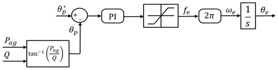
Figure 5.
Block diagram of the proposed current injection speed generator.
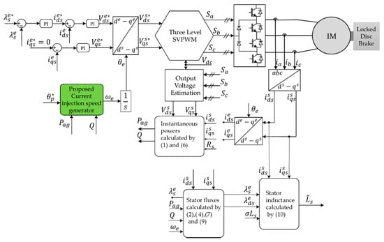
Figure 6.
Block diagram of the modified stator inductance identification process with the proposed current injection speed generator under locked-rotor standstill conditions.
Consequently, the stator inductor identification method based on a low-speed test can be modified by considering the locked-rotor standstill condition, as shown in Figure 6, because it is based on the modified inductance estimation equation and the proposed current injection speed generator. This modified low-speed AC injection method is more suitable for three-level NPC inverter-fed IMs than the previous method since it can identify the stator inductance not only under locked-rotor standstill conditions, but also under almost any load conditions.
4. Simulation Results
To verify the performance of the proposed stator inductance identification process, a simulation was conducted based on the parameters for an 18.5 kW IM, as shown in Table 1, with a three-level NPC inverter using a 600 V DC-link voltage. In the simulation, a comparison between the conventional and proposed low-frequency injection-based stator inductance identification methods was given under various load and speed conditions.

Table 1.
Parameters of 18.5 kW tested IM.
A comparison of the simulation results for the conventional identification method between the no-load and locked-rotor standstill conditions is shown in Figure 7. In this simulation, the injection frequency for the conventional method was defined as 2 Hz. Figure 7a shows the power angle () between the active and reactive power of the IM. In no-load conditions, the power angle always converges to zero since the air-gap active power becomes zero in a steady state, while the reactive power has a certain, non-zero value. However, in locked-rotor standstill conditions, the air-gap active power of the IM increases to a certain non-zero value and, therefore, the power angle increases significantly. As a result, the accuracy of the estimated stator inductance was very poor in locked-rotor standstill conditions, as shown in Figure 7b, because the air-gap active power must be low enough to be ignored for accurate estimation with the conventional method.

Figure 7.
Comparison of simulation results for the conventional stator inductance identification method in Reference [16] between the no-load and locked-rotor standstill conditions: (a) estimated power angles and (b) identified stator inductances.
Figure 8 shows the simulation results for the modified stator inductance identification method, based on Equation (10), in locked-rotor standstill conditions without the proposed current injection speed generator. As shown in Figure 8b, the modified identification method resulted in a more accurate stator inductance than the conventional method using a 2 Hz injection speed (cf. Figure 7b). However, this estimation result was still not acceptable. As shown in this figure, the estimated accuracy increased as the injection speed decreased. Furthermore, since the power angle () decreased as the injection speed decreased, as shown in Figure 8a, it was clear that the identification got more accurate as the power angle decreased; thus, the power angle can be controlled with the injection speed.

Figure 8.
Modified stator inductance identification method in locked-rotor standstill conditions at different speeds without current injection speed generator: (a) estimated power angles and (b) identified stator inductances.
Figure 9 shows the simulation results of the modified stator inductance identification method in locked-rotor standstill conditions with the proposed current injection speed generator. In this simulation, the proposed current injection speed generator was used to obtain a robust result of the estimation value by maintaining the power ratio to a certain value in any condition. As shown in Figure 9a, the power angle converged to its reference value, 0.78 rad in this case, using the current injection speed generator shown in Figure 6. Since the proposed injection generator used AC injection speed to control the power angle, the injection speed varied in the transient state, as shown in Figure 9b. Since the proposed current injection speed generator moved the power angle to a certain value, the accuracy of the proposed method was maintained under any conditions, and this resulted in an acceptable accuracy for the identified stator inductance, even in locked-rotor standstill conditions, as shown in Figure 9c.
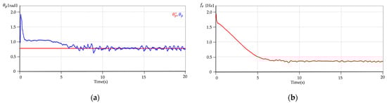
Figure 9.
Modified stator inductance identification method with proposed current injection speed generator in locked-rotor standstill condition: (a) reference and estimated power angles, (b) proposed injected frequency, and (c) nominal and identified stator inductances.
5. Experiment Results
In order to verify the stator inductance identification process with the proposed current injection speed generator, the proposed method was implemented for a three-level NPC inverter. Figure 10 shows the experiment setup with a three-level NPC inverter and an IM. The parameters of the IM were the same as for the simulation and are shown in Table 1, and the parameters for the inverter are shown in Table 2. Additionally, a disc brake mechanically connected to the IM was used in order to lock the rotor for the standstill condition. In the experiment, a three-level SVPWM and DC-link balancing algorithm were applied in the same way as they are in the conventional method [17,18].

Figure 10.
Experimental setup.
Table 2.
Parameters of three-level neutral-point-clamped (NPC) inverter.
Additionally, the switching frequency of the three-level NPC inverter was set to 2 kHz. Figure 11 shows the experiment results of the modified stator inductance identification method in the standstill condition with the proposed current injection speed generator. All of experiment results were measured by a digital to analog converter connected to an oscilloscope (PICOSCOPE 6403C).

Figure 11.
Modified stator inductance identification method with proposed current injection speed generator in locked-rotor standstill condition: (a) reference and estimated stator fluxes (b) a-phase current (c) reference and estimated power angles (d) proposed injected frequency.
As shown in Figure 11a, the estimated stator flux is converged to its reference value by the flux regulator as shown in Figure 6, and the magnitude of the stator current is changing according to the output of the flux regulator as shown in Figure 11b. Since the reference of the power angle () is set to , the power angle is adjusted by the proposed current injection speed generator during the identification process as shown in Figure 11c. Therefore, the injection speed () is changing according to the error from the power angle, as shown in Figure 11d, because the current injection speed generator controls the power angle by the injected frequency as shown in Figure 5. Figure 12 shows a comparison of the conventional and proposed identification method in the locked-rotor standstill condition. In Figure 12a, stator inductance is identified based on Equation (5) with constant low-speed current injection, while the stator inductance identified based on Equation (10) with the proposed current injection speed generator in Figure 12b. As a result of this comparison, the stator inductance identified by the proposed method is much more accurate than the conventional method, which has significant error comparing to nominal stator inductance in locked-rotor standstill condition.

Figure 12.
Comparison of identified stator inductances in locked-rotor standstill condition: (a) conventional identification method in [16] (b) proposed identification method.
The specific value of the identified stator inductance from the proposed and conventional methods in the locked-rotor standstill condition are listed in Table 3 for comparison. The nominal value of the stator inductance was identified based on a pre-running no-load test with acceleration and deceleration profiles for the rated speed, this is known to be the most accurate method. As shown in Table 3, identification error from the proposed method is less than 5% while the conventional method’s result is not acceptable with high estimation error because the conventional method takes only variable load condition into account. In conclusion, the proposed method can identify the stator inductance accurately even in the locked-rotor standstill condition.
Table 3.
Identified stator inductance of IM (locked-rotor standstill condition).
6. Conclusions
This paper presents a low-speed AC injection test-based stator inductance identification method for the locked-rotor standstill condition based on a proposed current injection speed generator. Since the proposed method can accurately estimate the stator inductance, even in locked-rotor standstill conditions, its overall accuracy under locked-rotor standstill conditions is better than the conventional low-speed test-based method. Therefore, the proposed identification method can be applied to a wide range of industrial applications without concern for any loss of identification accuracy. Since all the advantages of the conventional low-speed test-based identification method are maintained, the proposed method can be implemented very easily for three-level NPC inverter-fed IM drives. The simulation and experimental results verified the improved accuracy of the proposed method by comparing it to the conventional method.
Author Contributions
Y.K. and K.-M.C. conceived and designed the experiment; Y.K. performed the experiment; Y.K. and K.-M.C. analyzed the theory. Y.K. wrote the manuscript; K.-M.C., J.Y., and C.-Y.W. participated in the research plan development and revised the manuscript. All authors have read and agreed to the published version of the manuscript.
Funding
This work was supported by the National Research Foundation of Korea (NRF) grant funded by the Korea Government (MSIP) (No. 2019R1A2C2007216).
Acknowledgments
The authors gratefully acknowledge Seoho Drive Co., Ltd. for the experimental environment.
Conflicts of Interest
The authors declare no conflict of interest.
References
- Wu, B. High-Power Converters and AC Drives, 1st ed.; Wiley: New York, NY, USA, 2006; pp. 10–13. [Google Scholar]
- Schmitt, B.P.; Sommer, R. Retrofit of fixed speed induction motors with medium voltage drive converters using NPC three-level inverter high voltage IGBT based topology. In Proceedings of the International Symposium on Industrial Electronics (IEEE ISIE), Pusan, Korea, 12–16 June 2001; pp. 746–751. [Google Scholar]
- Three-Level AC Drive Eliminates Long Motor Cable Issues. Available online: https://www.pumpsandsystems.com/three-level-ac-drive-eliminates-long-motor-cable-issues (accessed on 16 June 2016).
- Trzynadlowski, A.M. The Field Orientation Principle in Control of Induction Motors; Academic Press: San Diego, CA, USA, 2001; pp. 191–201. [Google Scholar]
- Abu Rub, H.; Bayhan, S.; Moinoddin, S.; Malinowski, M.; Guzinski, J. Medium-voltage drives: Challenges and existing technology. IEEE Power Electron. Mag. 2016, 3, 29–41. [Google Scholar] [CrossRef]
- Carraro, M.; Zigliotto, M. Automatic Parameter Identification of Inverter-Fed Induction Motors at Standstill. IEEE Trans. Ind. Electron. 2014, 61, 4605–4613. [Google Scholar] [CrossRef]
- Peretti, L.; Zigliotto, M. Automatic procedure for induction motor parameter estimation at standstill. IET Electr. Power Appl. 2012, 6, 214–224. [Google Scholar] [CrossRef]
- Khamehchi, S.; Mölsä, E.; Hinkkanen, M. Comparison of standstill parameter identification methods for induction motors. In Proceedings of the 9th International Symposium on Sensorless Control for Electrical Drives (SLED), Helsinki, Finland, 13–14 September 2018; pp. 156–161. [Google Scholar]
- Feyzullah, E.; Bilal, A. A Robust Method for Induction Motor Magnetizing Curve Identification at Standstill. IEEE Access 2019, 7, 55422–55431. [Google Scholar]
- Odhano, S.A.; Cavagnino, A.; Bojoi, R.; Tenconi, A. Induction motor magnetizing characteristic identification at standstill with single-phase tests conducted through the inverter. In Proceedings of the 2015 IEEE International Electric Machines & Drives Conference (IEMDC), Coeur d’Alene, ID, USA, 10–13 May 2015; pp. 960–966. [Google Scholar]
- Ruan, J.-Y.; Wang, S.-M. Magnetizing curve estimation of induction motors in single-phase magnetization mode considering differential inductance effect. IEEE Trans. Power Electron. 2016, 31, 497–506. [Google Scholar] [CrossRef]
- Wang, K.; Yao, W.; Chen, B.; Shen, G.; Lee, K.; Lu, Z. Magnetizing curve identification for induction motors at standstill without assumption of analytical curve functions. IEEE Trans. Ind. Electron. 2015, 62, 2144–2155. [Google Scholar] [CrossRef]
- Ranta, M.; Hinkkanen, M.; Luomi, J. Inductance identification of an induction machine taking load-dependent saturation into account. In Proceedings of the 18th International Conference on Electrical Machines (ICEM), Vilamoura, Portugal, 6–9 September 2008; pp. 1–6. [Google Scholar]
- Zamora, J.L.; Garcia, C.A. Online estimation of the stator parameters in an induction motor using only voltage and current measurements. IEEE Trans. Ind. Appl. 2000, 36, 805–816. [Google Scholar] [CrossRef]
- Odhano, S.A.; Pescetto, P.; Awan, H.A.A.; Hinkkanen, M.; Pellegrino, G.; Bojoi, R. Parameter identification and self-commissioning in AC motor drives: A technology status review. IEEE Trans. Power Electron. 2019, 34, 3603–3614. [Google Scholar] [CrossRef]
- Khojakhan, Y.; Choo, K.M.; Won, C.Y. Stator inductance identification based on low-speed tests for three-level NPC inverter-fed induction motor drives. Electronics 2020, 9, 183. [Google Scholar] [CrossRef]
- Seo, J.H.; Choi, C.H.; Hyun, D.S. A new simplified space-vector PWM method for three-level inverters. IEEE Trans. Power Electron. 2001, 16, 545–550. [Google Scholar]
- Choudhury, A.; Pillay, P.; Williamson, S.S. Comparative analysis between two-level and three-level DC/AC electric vehicle traction inverters using a novel DC-link voltage balancing algorithm. IEEE J. Emerg. Sel. Top. Power Electron. 2014, 2, 529–540. [Google Scholar] [CrossRef]
Publisher’s Note: MDPI stays neutral with regard to jurisdictional claims in published maps and institutional affiliations. |
© 2021 by the authors. Licensee MDPI, Basel, Switzerland. This article is an open access article distributed under the terms and conditions of the Creative Commons Attribution (CC BY) license (http://creativecommons.org/licenses/by/4.0/).