Article

A Cascaded DC-AC-AC Grid-Tied Converter for PV Plants with AC-Link

by
Manuel A. Barrios
1,2,*,
Víctor Cárdenas
1,
Jose M. Sandoval
1,
Josep M. Guerrero
2,* and
Juan C. Vasquez
2
1
Engineering Department, Autonomous University of San Luis Potosi, Dr. Manuel Nava No. 8, Col. Zona Universitaria Poniente, San Luis Potosí 78290, Mexico
2
Center for Research on Microgrids (CROM), Department of Energy Technology, Aalborg University, 9220 Aalborg, Denmark
*
Authors to whom correspondence should be addressed.
Electronics 2021, 10(4), 409; https://doi.org/10.3390/electronics10040409
Submission received: 8 January 2021 / Revised: 28 January 2021 / Accepted: 4 February 2021 / Published: 8 February 2021
(This article belongs to the Section Power Electronics)

Abstract

:
Cascaded multilevel converters based on medium-frequency (MF) AC-links have been proposed as alternatives to the traditional low-voltage inverter, which uses a bulky low-frequency transformer step-up voltage to medium voltage (MV) levels. In this paper, a three-phase cascaded DC-AC-AC converter with AC-link for medium-voltage applications is proposed. Three stages integrate each DC-AC-AC converter (cell): a MF square voltage generator; a MF transformer with four windings; and an AC-AC converter. Then, k DC-AC-AC converters are cascaded to generate the multilevel topology. This converter’s topological structure avoids the per-phase imbalance; this simplifies the control and reduces the problem only to solve the per-cell unbalance. Two sets of simulations were performed to verify the converter’s operation (off-grid and grid-connected modes). Finally, the papers present two reduced preliminary laboratory prototypes, one validating the cascaded configuration and the other validating the three-phase configuration.

1. Introduction

At the end of 2019, the global renewable generation capacity was 2537 GW. Solar energy was the renewable energy with the most significant growth reaching a global capacity of 586 GW (23% of the global renewable generation capacity) [1] According to the global weighted-average levelized cost of energy (LCOE), the cost for electricity from utility-scale photovoltaics (PV) plants has fallen 82% in the last decade. Similarly, crystalline solar PV modules’ price has fallen 90% in Europe in the same period [2].
The fall in prices and the photovoltaics’ growth in the last years have required technologies and innovations advances in power electronic converters to connect large-scale PV power plants to the grid. Nowadays, the most widespread utility-scale topology to interface solar PV modules to the medium-voltage (MV) grids is the two- or three-level low-voltage (LV) centralized inverter [3,4,5]. This topology commonly consists of multiple PV arrays (the number of PV modules could easily reach millions of them [6]) attached to a DC-DC converter, increasing the PV array voltage and correctly feeding the low-voltage centralized inverter. Finally, a low-frequency (LF) transformer steps up the LV AC to generate the required voltage for a utility-scale grid (6–36 kV) [7,8,9,10,11].
This classic configuration faces some disadvantages. The main drawback is the line-frequency transformer. Even though manufacturers are trying to reduce and optimize the transformer’s space and volume, it is still huge, making installation and maintenance complex and expensive [8,12,13].
Another issue is the limitation (normativity and insulations) to 1 kV on the DC side. In addition, a high total harmonic distortion (THD) makes the use of line-frequency passive filter mandatory; nevertheless, due to the medium-frequency switching harmonics and high current levels, the filter’s efficiency is impaired.
As it was mentioned, the main problem with the classic configuration is the large transformer; hence, other works have tried to stay away from using it [14,15,16,17]. Thus, transformerless alternatives have been considered. These alternatives consist of using high-rated switches, but even with the state-of-the-art switches (6.5 kV), there is a limit in the inverter’s AC output voltage; in the best case, it could be 3.582 kV.
Another possibility of implementing the classic configuration to reach MV levels involves the series connection of multiple high-rated switches. This approach brings its challenges: problematic physical construction, intricate gate driver design, use of snubber networks, large filters, and high conduction losses due to the on-state voltage drop [18].
Multilevel converters have been proposed and used to overcome some of the previously discussed problems [12,19,20,21,22,23]. Multilevel converters show interesting features like direct integration to the MV grid if a suitable number of levels are applied; therefore, this converter could be considered a transformer-less converter for MV-grid integration [11,24,25]. Due to the high number of levels in a staircase form, the waveform in the converter’s output is closer to a sinusoidal signal; this implies that the THD could be minimal [10,25,26]. The two formers features can be achieved without using high-rated voltage switches; in other words, to achieve the MV levels and a low THD, commercial switches can be implemented [10]. The only issue to overcome is that the voltage required will increase accordingly to the MV-grid level.
Several multilevel converters have been proposed since the seventies, such as diode clamped also known as neutral point clamped (NPC), flying capacitor (FC), cascaded h-bridge (CHB), and the modular multilevel converter (MMC), among others. Still, the previous four are fundamental structures [27]. The diode clamped remains in use in the industrial environment [28,29]. The number of voltage levels produced by this converter is m, and requires m − 1 capacitors [30]. The capacitors are used as DC sources; therefore, the switches must block the capacitor’s voltage. The flying capacitor’s output levels are generated by the capacitors that float with respect to the ground potential; hence, the switch must block this voltage [31,32]. This topology provides redundant switching states that can balance the voltage in the flying capacitors [33]. The CHB converter is built cascading k full-bridge converters and requires multiple isolated DC sources [30]. The number of levels m and DC sources k are related as m = 2k + 1; therefore, a high number of DC sources are required [34]. PV farms commonly use multiple PV strings, and each PV string generates its own DC voltage. The MMC converter provides an alternative multilevel topology [35,36]. Three legs integrate an MMC converter, and each leg has two arms, and each arm has k cascaded converters; the MMC has a common DC source. The most common implementation is the HB converter. The main drawback in the use of MMC includes the circulating current between legs.
The newest and more complex multilevel converters are based on these four, and in some applications, the line-frequency transformer is required by means of isolation, normativity, or security. The sizing and design methods for eleven cascaded multilevel converter (CMC) were addressed in reference [20]. The authors also provide considerations and a detailed procedure for the power stage. A three-cell seven-level CHB was evaluated in reference [19], and the control method was based on traditional voltage-oriented control. This standard control scheme required the addition of two stages: one stage considers the maximum power point tracking (MPPT) for each module or string, and the other stage controls the DC-link voltages drift. In reference [22], a current-control technique and the switching scheme of a cascaded five-level inverter with a single-phase photovoltaic grid-tied system were introduced. In reference [23], a cascaded H-Bridge multilevel converter for photovoltaic systems without voltage or current sensors at the DC-side was proposed. The effectiveness of the proposed structure was experimentally validated on a 2 kW single-phase seven-level CHB laboratory prototype.
In the last decade, MF transformers have been considered to minimize the size and weight of the line frequency transformers in traditional PV farms connected to the grid; but this MF link requires an additional step to transform the MF-AC square voltage to line-frequency AC voltage. There are two options to perform the frequency transformation: the first option is a two-step power conversion (AC-DC/DC-AC), in which a MF rectifier produces a new DC link that feeds an inverter converter [37,38]. Reference [12] presents a high-performance solution based on a power electronic transformer (PET); it included a medium-frequency transformer, DC-links, and multilevel converters on the low-voltage or on the high-voltage side. In reference [21], a high-frequency link-cascaded medium-voltage converter was proposed for direct grid integration of renewable sources. The common magnetic link generates several isolated and balanced DC sources for feeding all the h-bridge inverter cells of the MMC converter.
A direct stage conversion (AC-AC) is the second option to transform an MF-AC voltage to low-frequency AC voltage [39,40,41,42,43]. In reference [44], a direct method conversion was implemented. The converter has four stages of energy conversion: DC-DC/DC-AC/AC-AC/AC-AC. The converter uses a switching frequency of 2880 Hz and the work focuses on the designing and operation of the converter under unbalanced insolation. Finally, presenting an experimental test: in three-phase (3PH) and in single-phase (1PH) cascaded configuration, in which it reports an operating of 450 W. Besides, there are tests to validate the zonal power balancer, but there are not close-loop experimental tests of the proposed converter neither in three-phase configuration nor cascaded configuration.
This paper presents a multilevel medium-voltage power converter with MF-AC links that simplifies the grid integration of large-scale PV farms. This proposal overcomes some drawbacks related to grid-tie PV plants: use of line-frequency transformers and filters; avoiding using high-rated switches (>6.5 kW) or the use of series connection switches; elimination of the MF rectifying stage; and promoting modularity.
This three-phase multilevel converter is built cascading some converters interconnected with each other via medium-frequency multiple winding transformers. These transformers generate a MF-AC link. In the primary side, there is only one winding supplied by a square-wave converter. There are three windings on the secondary side; each winding plus a suitable converter generates each of the three-phase output voltages.
This topology has been selected because it has some exciting features: (1) It includes medium-frequency AC links (MF transformer). (2) MF switching, which allows the reduction of passive elements. (3) AC-AC direct conversion from MF-AC voltage to LF-AC voltage eliminates the necessity of a medium-frequency rectifier. (4) Multiple DC links. (5) Multilevel output voltage that in consequence, permits interfacing with medium-voltage utilities with a low THD. (6) Does not require a line-frequency transformer. (7) Modularity (multiple DC-AC-AC converters can be cascaded) [45].
The rest of the document is organized as follows: Section 2 describes the proposed converter topology, its modulation strategy, and the proposed converter’s design. Section 3 discusses the three-phase multilevel converter’s control strategy. Section 4 shows simulations to validate the operation of the proposed topology in open-loop under off-grid mode as well as in close-loop under on-grid mode. Section 5 discusses experimental tests over two laboratory prototypes. Finally, in Section 6, the discussion is presented.

2. Grid-Tied Converter with AC Link

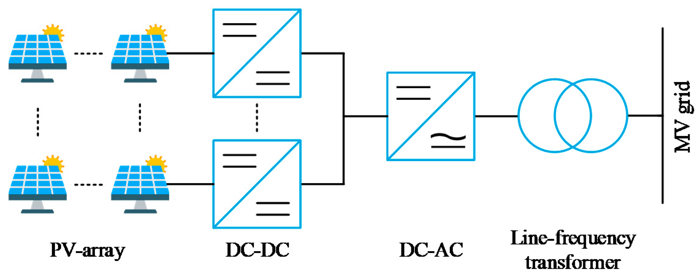
Besides many other state-of-the-art topologies, the one proposed in this paper is integrated by some conventional converters that combined present exciting features. In Figure 1, the proposal multilevel grid-tied converter with MF-AC links is depicted in the form of a block diagram. The suggested converter facilitates the incorporation of utility-scale PV plants into the MV utility. Figure 2 shows the block diagram of the conventional two-levels centralized converter for medium-voltage levels in comparison with the proposed converter.
This proposed topology is built cascading k three-phase DC-AC-AC converters. Some converters integrate this DC-AC-AC converter; one is referred to as the input converter and the others as the output converters. The input and output converters are interconnected through a medium-frequency multiple winding transformer that isolates the PV arrays from the utility. The multiple winding transformer involves four windings. The first winding is the primary, and it is connected with the input converter. The rest of the windings integrate the secondary; thus, the secondary and its corresponding output converter (each winding is connected to one output converter) generate a three-phase electrical system.
To cascade the DC-AC-AC converter and achieve the multilevel output voltage, the converters connected to the MF transformers’ secondary windings are cascaded with their corresponding windings from other multiwinding transformers. The multilevel output voltage will present a low THD that depends on how many converters are cascaded. This work considers three cascaded converters to simplify the analysis and the simulations’ running time, but in general, the number of cascaded converters (cells) may be k.

2.1. The Single-Phase DC-AC-AC Converter

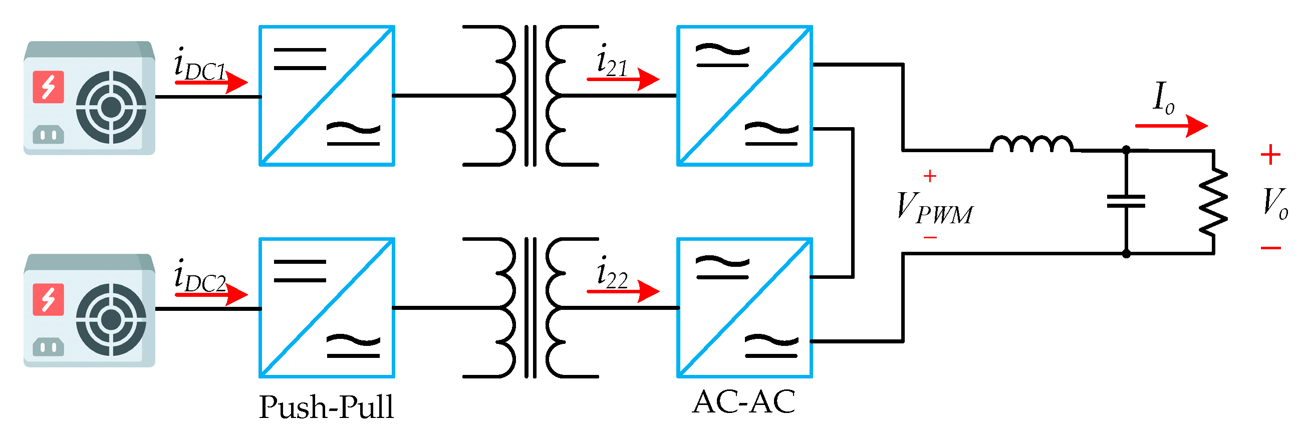
To understand how the entire proposed topology works, Figure 3 shows the block diagram of the DC-AC-AC converter in a single-phase configuration. The series connection of more than one 3PH DC-AC-AC converter builds the multilevel structure.
The block diagram is explained from left to right because the power flow from the PV plant goes in that direction:
  • The PV modules are the first stage; they are interconnected in serial parallel arrays to satisfy the design and regulations’ power levels. For the purposes of this explanation, the PV modules are replaced by ideal DC power supplies.
  • The second stage converts the DC voltage from the PV modules to a medium-frequency square AC voltage. Many converters can do this work half-bridge, full-bridge, push-pull, flyback, dual-active-bridge, and others.
  • The third stage consists of a ferrite-based medium-frequency transformer, which isolates and steps up the voltage. The primary winding is plugged into stage two, and the secondary winding feeds stage four.
  • The fourth stage has the task to convert a MF-AC voltage to a low-frequency AC voltage. There are two methods to accomplish that task: a two-step (involves a MF rectifier and an inverter) and a direct approach. The direct method could eliminate the MF-rectifier, get bidirectional power flow, and improve efficiency.
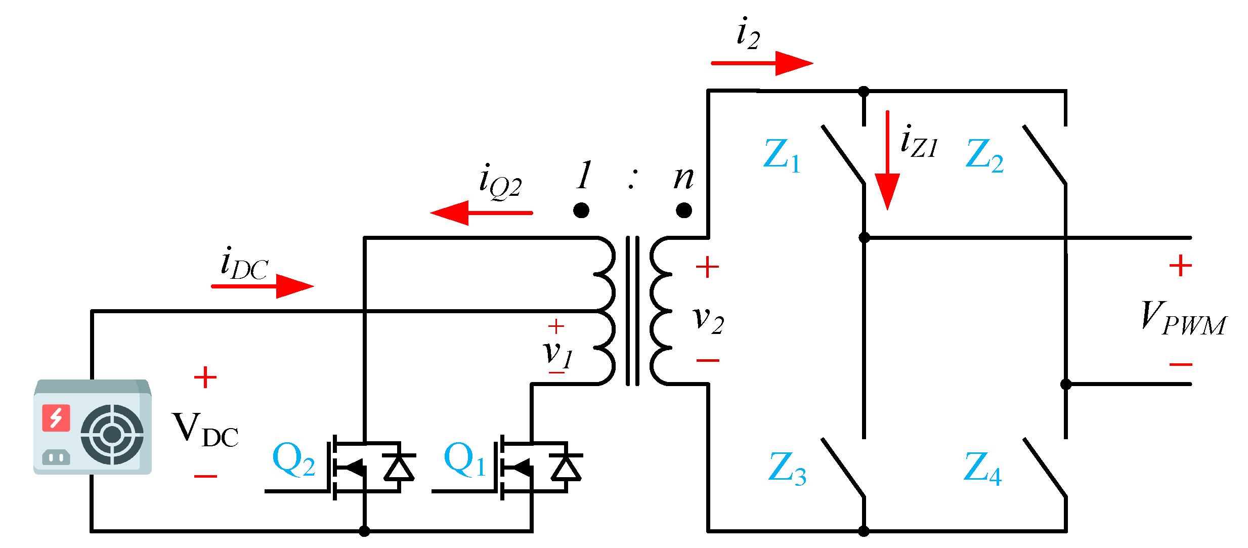
Figure 4 presents a schematic view of the DC-AC-AC converter. As in Figure 3, the PV arrays were interchanged by ideal DC power supplies to facilitate the explanation. The DC supply feeds a push-pull converter that works as a MF square wave voltage generator (second stage).
The push-pull converter uses a transformer action to transfer power from the primary side to the secondary side. This converter requires two switches operating alternatively (Q1 and Q2); this means that only one switch is ON for the entire duration of the switching period. This operation could be reflected in lower conduction losses. In addition, this symmetric configuration of the switches reduces the radiated electromagnetic emissions (also, minimizing the transformer’s leakage inductance is vital to minimize the electromagnetic interference. Moreover, the two identical low-side switches’ implementation requires only one DC supplier for the gate driver. The transformer action regulates the output voltage in v2 in a feed-forward manner; therefore, the output voltage solely depends on the transformer turn ratio and the DC power supply value. The magnetic core is efficient because the flux accumulation in one polarity is canceled in the other due to the bipolar operation. One overcome is that the switches have to support two times the voltage of the DC power supply. Due to the features mentioned above, the push-pull converter is implemented in the second stage.
Regarding the fourth stage, a couple of converters can directly convert a MF-AC voltage to line-frequency voltage (also known as AC-AC converters or Matrix converters); the half-bridge converter and the full-bridge are the most widespread. Because of the push-pull converter, it is impossible to ensure zero volts systematically; only +VDC and −VDC are possible; therefore, it is necessary to choose the full-bridge converter. The final objective of this converter is to inject the sinusoidal current waveform into the utility.
There are two switching strategies to operate an AC-AC converter: switching controlled by current and switching controlled by voltage [46,47,48]. The second one is the most convenient solution for the proposed DC-AC-AC converter because the push-pull converter and the full-bridge converter can be synchronized easily [49]. It is essential to determine that the standard sign over the load voltage is always retained. Hence, to operate the converter correctly, the commutation strategy should change the polarity on v2 from the load point of view. For example, if the voltage on VPWM is required to be positive when v2 is negative, then Q2, Z2, and Z3 must be ON; in this case, the voltage on the VPWM terminals will be negative.

2.2. Modulation Strategy for a Single-Phase DC-AC-AC Converter

The modulation strategy must synthesize a square MF-AC voltage from v2 into an equivalent sinusoidal pulse width modulation (SPWM) in the VPWM’s terminals of the full-bridge converter. The input and output converters must be synchronized and commuting at the same frequency rate to reach this objective. A variant of the unipolar SPWM is the modulation implemented on AC-AC converter. Compared with bipolar SPWM, the unipolar SPWM can effectively double the switching frequency. This benefit is appreciated in the harmonic spectrum of the output voltage waveform. The harmonic components related to the switching frequency and their sidebands are canceled; besides, the dominant harmonic located at the double the switching frequency is withdrawn but not their bands [50]. Due to the actual DC-AC-AC converter being a three-phase system, there are three AC-AC converters. The previous strategy is extended using three modulation waveforms and its counter-phase waveforms; thus, each pair of the modulated signal is shifted 120° from each other.
The output voltage of the proposed converter (Figure 1) is multilevel; hence, it is important to apply a proper modulation technique. Due to its benefits [51], phase-shifted multicarrier sinusoidal PWM (PSPWM) modulation is chosen. The effective switching frequency (m − 1)fc obtained with the PSPWM modulation in the output voltage VPWM is an attractive feature. In other techniques, this frequency is not as high as in PSPWM. A direct effect of implementing the PSPWM, considering a low-frequency modulation ratio mf, is a widely free zone of switching harmonics; the most significant harmonic appears at (m − 1)fc. In this modulation, the amplitude and frequency of all triangular signals are the same, but they are 360°/(m − 1) phase-shifted from each other, and the number of carriers is (m − 1).

2.3. Design of Seven-Levels 3PH DC-AC-AC Converter

As stated earlier, multilevel topologies allow for high-voltage levels, effectively increasing the output frequency [33,44,50], and low THD due to the lower harmonic content. Other exciting features come from three-phase systems; the magnetic link makes it possible to cancel the single-phase component found twice in the line frequency in the DC current waveform. In Table 1 are the main parameters that this design will consider for the seven-levels 3PH DC-AC-AC converter.
Let m be the number of voltage levels at the output, then the required number of independent DC sources is
k = ( m 1 ) / 2 = 3 ,
and each independent DC source should have the same voltage amplitude. Due to each AC-AC converter producing a fundamental frequency component Vo1, Vo2, and Vo3, then the Vo is given by the output voltages addition of each cascaded converter
V o = V o 1 + V o 2 + V o 3 ,
considering that the phase to neutral voltage (Vo) is Vo = Vop sin(ωot), with ωo = 2πf. It is known from the three-phases electrical system that the rated output power of a converter is
P o = 3 V o p I o p 2 = 3 V L L I o = 3 V o I o ,
and when contemplating the values from Table 1, the root meand square (RMS) output current (Io) results in 14.17 A and RMS Vo is 7.62 kV. With the output current, the equivalent resistive load per phase is
R o = 3 V o 2 P o = 537.52   Ω
When the modulation index is 0.9, the transformer turns ratio results in
n = V o p k m a V D C = 3.99 ,
and it should warrant the system’s operation with a minimum voltage in the input supply and the maximum load, considering that the modulation index at 0.9 is high. Hence, let n be 4.5; this results in a new modulation index of 0.7983.
As the value of the DC source is known as well as the transformer turn ratio; then, the MF-transformer’s voltages across the three secondary windings are
| v 2 | = n V D C = 4.50   kV ,
and its corresponding peak current can be calculated as
i 2 p = 2   I o = 20.05   A
If there are no losses in the process of energy transformation, the average and peak current [52] in each of the k DC input supplies are
I D C = P o k   V D C = 72.03   A ,
I D C p = 3 n i 2 p 2 = 191.40   A .
correspondingly. Finally, the selection of the DC-link capacitor is calculated as follows
C l i n k = P 2 π f o Δ v D C v D C = 6878.88   μ F .

3. Control Strategy

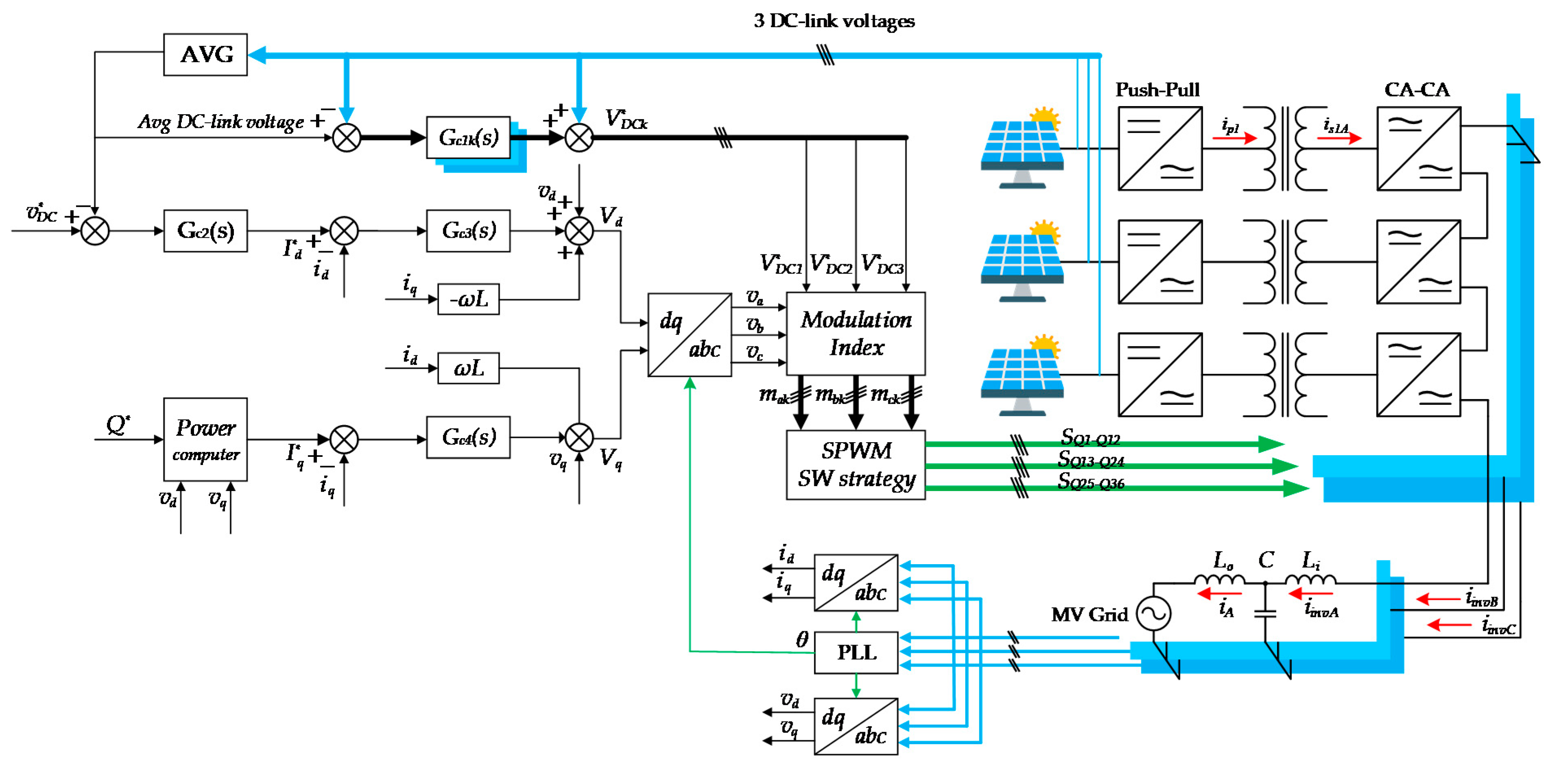
Figure 5 displays the control scheme of the proposed converter. A 3PH phase-locked loop (PLL) is implemented to synchronize the converter with the grid; an inductance-capacitance-inductance (LCL) filter interconnects the multilevel converter with the utility. As usual in grid-tied converters, one external loop and one internal regulates the converter by means of the voltage-oriented control (VOC) under the synchronous rotating reference frame.
The cascaded DC-AC-AC converters will work together as a controlled current source feeding the utility, as shown in Figure 1. Because PV arrays work as a current source, their voltages are dependable on the current extracted and the level of light intensity; in other words, the PV arrays’ output voltages depend on the operating point in the PV curves (current versus voltage and power versus voltage). Note that the cascaded DC-AC-AC converters have the same circulating current in each phase (ia, ib, and ic); therefore, it is challenging to carry an independent grid current-control loop to regulate each DC-link voltage. Thus, the k DC-link voltages’ average must be computed into a single cascaded grid current-control loop as was proposed in [53].
The current-control loop (the inner loop) in practice should be designed to be faster than the outer loop to follow the given reference. Hence, the inner loop controls the current injected to the utility employing a simple PI controller through dq→abc transformation, considering decoupling between Id and Iq control. va, vb, and vc are generated after the transformation from dq frame to abc of the control signals Vd and Vq.
In the external control loop Gc2(s), the k DC-link voltages’ average is regulated to control the cascaded converters’ output power. If the DC link is controlled to be constant, then the energy extracted from the PVs can be injected into the grid by charging and discharging the DC-link capacitors. To achieve this, the PV power and the active output power should be in equilibrium employing the instantaneous power theory [54]. In general, the outer control loop will generate the current reference for the inner loop Gc3(s). The previous sentence means that the deviation of the averaged of the k DC-link voltages from the reference value is reflected in the inner current loop to adjust the control signals V*d and V*q.
The signals va, vb and vc cannot be directly applied to the SPWM generator to control the converter. If this happened, then the DC-link capacitors would suffer a voltage deviation because of different operating conditions created by unequal power distribution between the cells. Commonly, there are two types of power imbalance: per-cell and per-phase.
Because of this converter’s nature and configuration, the per-phase power imbalance does not occur; this is an outstanding advantage compared to other topologies in the state-of-art. In those topologies, each phase and each cascaded converter are fed with an independent source of powers (PV + DC/AC converter). On the contrary, in this paper’s proposed topology, the three-phases of each cascaded converter (DC-AC-AC converter) are fed with the same source of power; this is a natural balance due to the magnetic link. Therefore, the problem is reduced to solve the per-cell imbalance. In reference [55], a power-imbalance method was described. This method is based on sharing the cascaded converters’ usage equally in the same amount of the imbalance.
The per-cell imbalance occurs when each DC-AC-AC converter’s power processes are not equal (Pa1 ≠ Pa2 ≠ Pak). The per-cell imbalance affects the DC link since it is controlled like the average of the k DC-sources; thus, there is no certainty on how each DC-link voltage will react, but a voltage drift of the DC links will happen, distorting the converter voltage. To surmount the drift problem in the DC-link capacitors, it is necessary to compensate the voltage reference signals va, vb and vc in the modulation stage using a feed-forward mechanism that considers each of the DC-link voltage deviations.
The k DC-link voltages pass through the controller Gc1k(s) to perform feed-forward compensation. The output of the controller reflects each deviation of the corresponding DC-link voltage from the average reference value. The three-phase voltage reference signals va, vb and vc are divided by the modified DC-link voltages (V*DCk) coming from the addition of Gc1k(s) with VDCk; as a result, k groups of independent modulation indexes are generated for each of the k DC-AC-AC converters. The changes to the respective modulation indices affect the current that the converter draws from the corresponding DC-link capacitors and thus alter the DC-link voltages. In this way, the k DC-link voltages are regulated to a given reference value (1 kV in the simulations).
The unbalanced situation limits the harmonic components’ cancellation in the kth carrier group produced by each cascaded converter; as a direct effect of this dilemma, the VPWM voltage’s THD increase. Consequently, the free zone of switching harmonics is reduced because the most significant harmonic appear at 2fc. Various THD minimization methods have been proposed to extend the free zone of harmonics during unbalanced situations. By removing the low-order harmonic distortion found in the unipolar pulse-width carrier frequency, these methods optimize the multilevel converters’ switching angles.

4. Simulations

This section is divided into two subsections: open-loop off-grid mode and closed-loop on-grid mode. The first section is about the power electronics system’s performance and the validation of the proposed converter considering ideal DC power supplies. The close-loop section will explain how the converter is controlled while it is connected to the grid.

4.1. Open-Loop Off-Grid Mode Simulations

To verify the system’s proper operation, some off-grid simulations were done (Figure 6 and Figure 7). The line-to-line voltage is set to 13.20 kV, and the total power output is 324.16 kW.
As was discussed in previous sections, three cascaded converters are considered. Due to off-grid mode, a resistive load is connected through an inductance-capacitance (LC) filter. Some simulation’s parameters are listed in Table 1 and others are obtained from equations 1 to 10. In this simulation, the PV arrays were substituted by ideal power supplies.
Figure 6 shows the most representative waveforms in this proposed converter. Figure 6a shows the voltage one of the three DC power supplies. Its value is 1 kV; therefore, the push-pull converter’s power switches will block 2 kV; hence, it is recommendable to use switches with a blocking voltage of 3.3 kV. Since the DC voltage should not be higher than 1 kV due to safety and insulation constraints, a transformer must be implemented to step up the voltage. In this simulation, v1 is scaled up through the transformer’s turn ratio from 1 kV to 4.5 kV; v2A, v2B, and v2C are identical; this is depicted in Figure 6b, where the medium-frequency square waveforms are presented on the left side, and a zoomed view is shown in the right side.
In Figure 6c, the cascaded three-phase converters generate the seven-level line to neutral voltages in VPWM terminals; its peak voltage reaches 13.5 kV and the THD is 20.64%. The blocking voltage associated with the AC-AC converter’s switches is 4.5 kV; therefore, 6.5 kV IGBT collector-emitter voltage is suitable for this stage [56]. If more AC-DC-DC are cascaded, then the voltage rating of the semiconductors will decrease linearly. For example, suppose 3.0 kV devices are used and considering a derating of 50%; in that case, nine cascaded converters will be required to generate a stare output voltage of 13.5 kV peak. Finally, in Figure 6d, the three-phase sinusoidal line to neutral voltages are present, clearly shifted 120° one after another; the fundamental component is 60 Hz, with a peak value of 10.77 kV. The RMS phase-neutral and line-line voltages are 7.62 kV and 13.2 kV, respectively.
Figure 7 shows the most relevant current waveforms of the converter. Figure 7a illustrates the current waveforms in the first DC-link; its average and peak current values are 110.11 A and 191.40 A, respectively. The first impression when the DC link current is seen in detail is that there is a harmonic situated at six times the fundamental frequency, but after verifying the harmonic spectrum in Figure 7b, it is evident that the DC components are the only low-frequency harmonic. This is supported by the fact that the simulations consider a three-phase system balanced; therefore, the second harmonic current component is canceled via the magnetic link. Thus, the ripple current’s shape is only related to the medium-frequency switching harmonics in the power switches. In Figure 7c, the secondary windings current waveform are illustrated, one per secondary winding. Its peak current is 20.05 A in any of the medium-frequency transformers. Finally, Figure 7d shows the pure sinusoidal current waveform throughout the resistive load; the RMS and peak currents on each phase are 14.017 A, and 20.05 A, respectively.

4.2. Closed-Loop On-Grid Mode Simulations

The next simulations (Figure 8 and Figure 9) use a SW250poly PV module (SolarWorld, Bonn, Germany); the main parameters of the PV module are as follows: cells per module are 60; the voltage at maximum power (Vmpp) is 30.8 V; current at maximum power (Impp) is 8.12 A; and the maximum power (Pmax) is 250 Wp. Therefore, 2000 cells are considered to reach 1000 V, and thirteen PV modules parallel integrate the PV array. The DC-link voltage reference is 1000 V; the grid’s line-to-line RMS voltage is 13.20 kV. The grid’s interconnection is through an LCL filter, which values are 60 mH, 100 nF, and 170 µH, respectively.
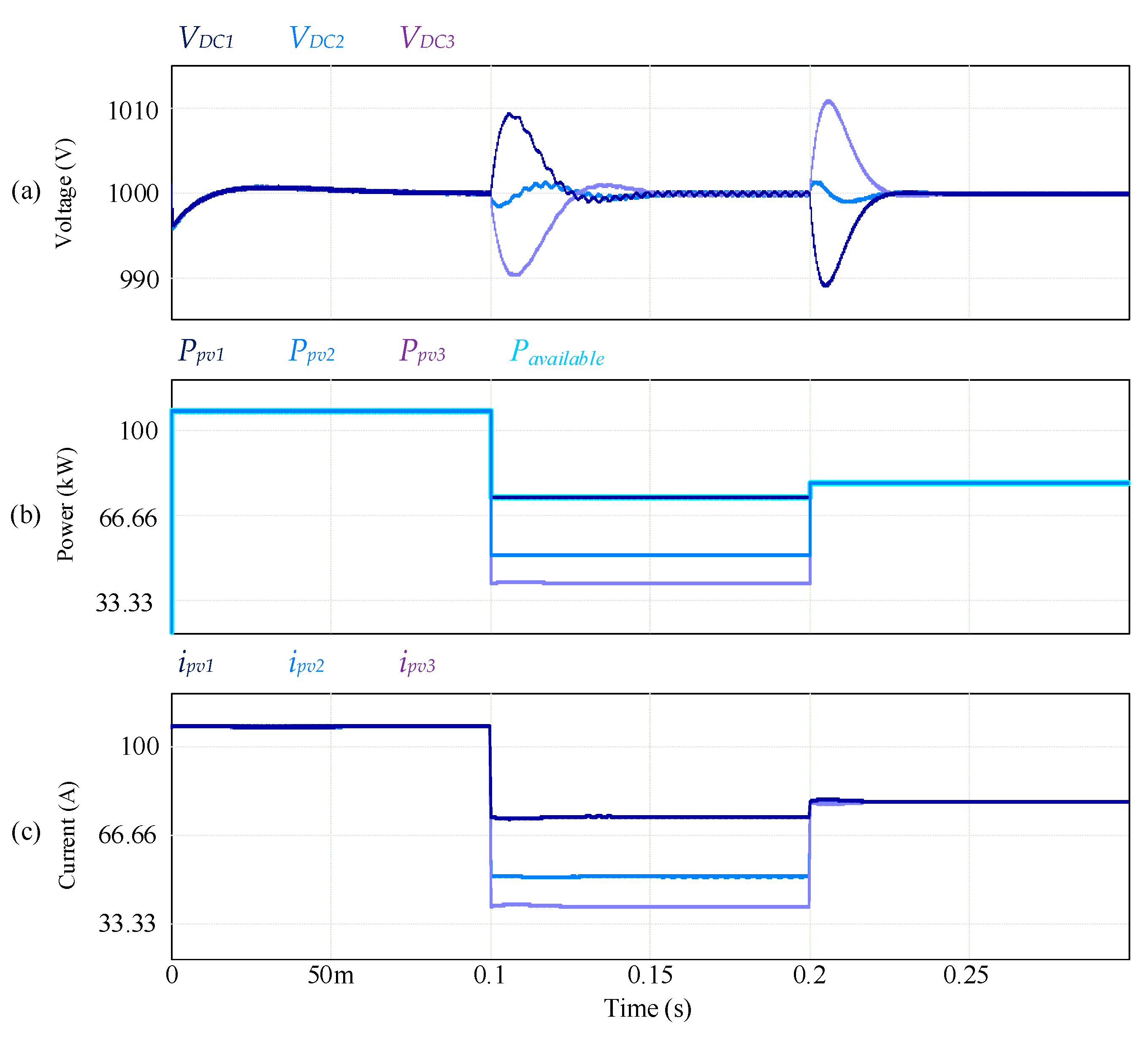
In Figure 8, the most representative waveforms of the simulation are drawn as follows: (a) DC-link voltages; (b) power available versus power generated in the PV; and (c) PV currents. This scenario is described as follows: the light intensity for the three PV arrays is 1000 W/m2 for the time t interval given in seconds s, 0 ≤ t < 0.1 s; this means that the voltages’ values, powers, and currents remain equal in any of the three sets. The magnitude of three DC links voltages, the available and the harvesting powers, and the currents are 1 kV, 108.05 kW, and 108.05 A, respectively.
In the next interval, 0.1 s ≤ t < 0.2 s, the light intensity changes accordingly: PV1 = 800 W/m2, PV2 = 500 W/m2, and PV3 = 400 W/m2. This change of light intensity produces several disturbances in the three sets of waveforms. First, the DC-link voltages got an overshoot; the maximum overshoot belongs to VDC1 = 1009.51 V, with a settling time of 55.5 ms. Second, each PV array’s available power decreased from 108.05 kW in every PV array to 74.16 kW, 51.57 kW, and 40.28 kW for PV1, PV2, and PV3, respectively. By the time t, reaches 155.5 ms, the harvested power equals the available power in the PV arrays. Third, the PV’s current also is affected; they drop immediately following each irradiation. However, they slowly climb up while the external loop regulates the DC-link voltage. As in the available power’s waveform, at t = 155.5 ms, each PV current reaches the Impp with the given light intensity (74.16 A, 51.57 A, 40.27 A).
The last interval considers from t = 0.2 s until t < 0.3 s; the light conditions changes as follows: PV1 = PV2 = PV3 = 850 W/m2. The waveform’s behavior in the steady state will be similar to the case where the light intensity was 1000 W/m2; therefore, the explanation will be brief. The DC links show a transitory; in this case, the overshoots are slightly superior to the previous case, but after 25 ms, the DC links get controlled to 1 kV. In Figure 8b, the extracted PV power in the three PV array increases to 79.81 kW. These waveforms present a negative overshoot because the maximum power cannot be surpassed; in other words, this is an effect of the PV currents, which have a spike. (c) the steady-state PV currents are 79.81 A.
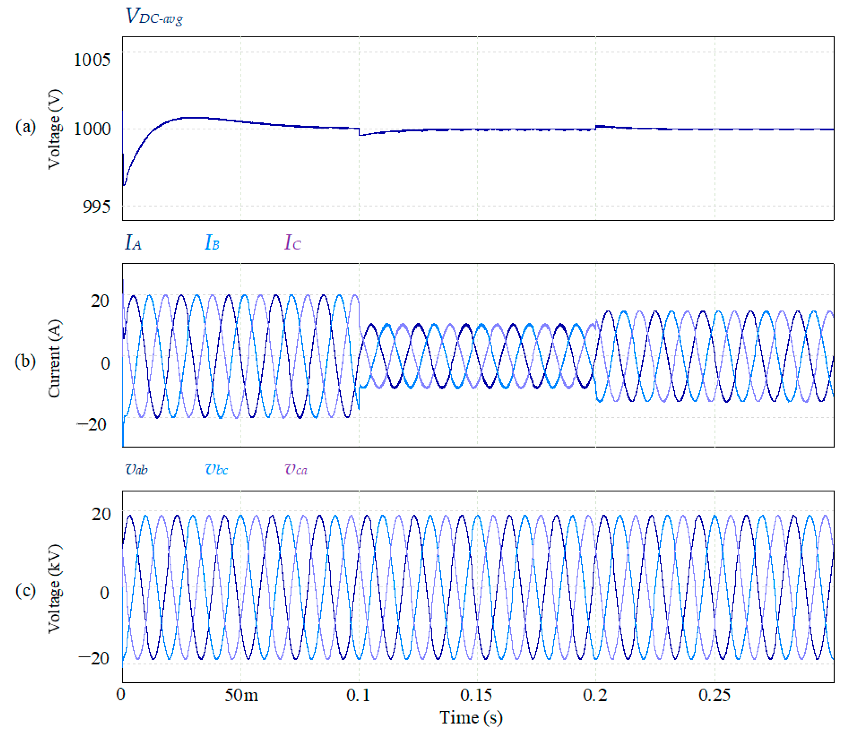
The test continues in Figure 9. Here also there are three sets of waveforms: (a) The average DC-link voltages, (b) the grid injected currents, and (c) LCL’s capacitor voltages. At the beginning of the simulation, a transitory with a peak time equal to 31.25 ms. At t = 0.1 s, the first S0 step is materialized; its effect is seen in (a), (b), and (c) as happened in the previous figure. The set (a) shows the little perturbation that the averaged DC-link suffers. The inductor’s current is well controlled, as can be seen in Figure 9b. There are not considerable overshoots; on the contrary, its shape is purely sinusoidal. In the first interval of time, the RMS value is 14.16 A; during the next period (t = 1 to t < 2) the RMS currents drop to 7.29 A, and this magnitude is reached after 0.352 ms.
Finally, in Figure 9c are the capacitor’s voltage; at t = 0.1 s, there is no deformation of the sinusoidal waveforms, perhaps the solar intensity change. Its RMS value remains constant the entire test (13.20 kV line-to-line). From t = 0.2 s until t < 0.3 s, other transitory shows up in the DC links. This voltage drift at t = 0.2 s can be practically neglected; at the end of this interval, the voltage settles at 1.0 kV. Regarding the injected current to the grid, its RMS value increases to 10.45 A. Lastly, the capacitor’s peak voltage continues stable (18.67 kV) with no alteration all the way to the interval.

5. Experimental Results

In order to verify the analysis and simulation results, two reduced versions of a laboratory prototype were built: a five-level single-phase DC-AC-AC converter (Figure 10), and a three-level three-phase DC-AC-AC converter (Figure 11). These reduced versions are focused on validating the conceptual idea of the proposed topology. These scaled-down converters are off-grid, and a resistive load is used in the converter outputs after an LC filter.

5.1. Single-Phase Multilevel DC-AC-AC Converter

The first reduced version consists of two cascaded DC-AC-AC converters; the diagram is shown in Figure 12. A single-phase DC-AC-AC converter (Figure 10a) is built with six IXTT69N30P MOSFETs (Littelfuse, Chicago, IL, USA), two for the push-pull converter and four for the AC-AC converter. Each switch in the AC-AC converter is integrated by a MOSFET and a diode bridge which gives the feature of a bidirectional switch. Four 15ETH03 diodes (Vishay, Malvern, PA, USA) were selected for the diode bridge. Regarding the medium-frequency transformer, an ETD-59 transformer core (TDK Corporation, Tokyo, Japan) with N97 material was selected. Switching signals are generated in a TDSM28F379D DSP (Texas Instruments Incorporated, Dallas, TX, USA) and postprocessed for the switching strategy in a FPGA Nexys 4 (Digilent, Pullman, WA, USA).
The parameters of the single-phase DC-AC-AC converter are the following: output RMS voltage Vo = 127 V; input voltage DC source VDC = 120 V; switching frequency fsw = 9.960 kHz; line-frequency fo = 60 Hz; output inductance L = 1.8 mH; output capacitance C = 3.5 µF; resistive load R = 20 Ω; transformer’s turn ratio n = 2; and modulation index ma = 0.75.
Figure 13a exhibits the most representative voltage waveforms of a single cell. Channel (Ch) 2 illustrates the square MF AC voltage v1 of the transformer’s primary winding; the duty cycle of v2 is 50%. Ch3 shows the voltage v2 in the transformer’s secondary winding, the voltage of v2 is n times v1. Finally, Ch4 depicts the three-level voltages in VPWM obtained due to the unipolar SPWM modulation technique; its amplitude is directly related to the voltage present on v2.
The main current waveforms are in the oscilloscope’s screenshot in Figure 13b. Ch2 shows the current iDC in the DC link; this current is the same that is flowing through the MF transformer’s central tap. The shape of the current waveform of iDC is similar to DC-link current in a two-level inverter. The average and peak currents of iDC can be calculated according to Equations (8) and (9). In contrast with the simulations where no overshoots were presented, the MF transformer’s central tap current shows overshoots of approximately 20% in the experimental results. Ch3 displays the current i2 in the MF transformer’s secondary winding; its RMS value is 4.16 A. Ch4 reveals the current io that flows in the resistor its RMS, and peak values are 6.26 A and 8.85 A, respectively.
Regarding the single-phase multilevel configuration, Figure 10b is the actual setup’s photography. Figure 14a shows the main experimental results based on the multilevel configuration; two cascaded 1PH DC-AC-AC converters are used to generate the five-level output voltage. Ch3 shows the five-level output voltage VPWM with an approximate amplitude of 480 V. Ch4 is the output voltage after the LC filter, with a RMS value of 207 V. The voltages spikes in the total VPWM terminals are generated due to the delivery of the energy of the MF transformer’s leakage inductance when the current path is broken due to the hard-switching commutation in the matrix converters. Ch1 reveals the RMS current on the resistive load; its RMS value is 7.49 A. Finally, the mathematical channel indicates the output power measured in the resistive load, and its value is 1.54 kW, (770 W per converter).
Figure 14b presents more experimental results in the multilevel configuration. In this scenario, one of the two cascaded DC-AC-AC converters is inactive, while the other is active. Considering that each division represents 4 ms, the second DC-AC-AC converter is turned on t = 18 ms. As seen in the waveforms, the introduced perturbation does not generate any disturbing voltage or current overshoot. Ch1 presents the current in the resistive load; its peak value changes from 9.40 A to 18.60 A. Ch3 illustrates the voltage before the LC filter; its waveform changed from three levels (with a peak value of 239.80 V) to five-levels (with a peak value of 479.10 V) after the second converter is turned on. Ch4 depicts output voltage after the LC filter; the peak voltage changed from 141.00 V to 294.00 V.

5.2. Three-Phase DC-AC-AC Converter

The second reduced version consists of one DC-AC-AC converter in a three-phase configuration; the diagram is shown in Figure 15. The 3PH DC-AC-AC converter is assembled with four IXTH36N50P MOSFETs (Littelfuse, Chicago, IL, USA) for the AC-AC converter, and two IXFK100N65X2 (Littelfuse, Chicago, IL, USA) integrate the push-pull converter. The bidirectional switches are integrated in the same way that in the first reduced version.
Regarding the medium-frequency transformer, an EE 110/36 transformer core (TYDZ, Guangzhou, China) with PC40 material was selected. The modulation strategy was generated in dSPACE environment through a DS1006 processor accompanied by a DS5203 board (dSPACE GmbH, Paderborn, Germany). This last board was programmed with the RTI FPGA Programming by Xilinx System Generator Simulink blockset.
This converter was designed to be one of the three cascaded 3PH DC-AC-AC converter. The parameters of the converter are the following: output voltage VLL = 55.0 VRMS; input voltage DC source VDC = 60 V; switching frequency fsw = 10 kHz; line-frequency fo = 50 Hz; output inductance L = 1.8 mH; output capacitance C = 27 µF; transformer’s turn ratio n = 1.34; and modulation index ma = 0.55.
Figure 16a presents the waveforms generated by phase A of the three-phase DC-AC-AC converter. Ch1 illustrates the current through the resistive load of phase A; its RMS value is 136.0 mA. Ch3 and Ch4 are the line to neutral output voltages of VPWMA and VA. Its amplitudes are 45.0 V and 90.0 V, respectively. Both voltages are measured before and after the LC filter. Figure 16b depicts the line-to-line VPWM output voltages before the LC filter, its shape has five levels as expected, and the peak-to-peak voltage for each phase is 360.0 V.
The next figure represent the line-to-line voltages and currents in the converter. In this case the line to line voltages are measured after the LC filter, the results are shown in Figure 17a; the peak-to-peak and the RMS values are 165.0 V and 54.9 V, respectively. Finally, in Figure 17b are the three-phase output currents with an RMS value of 137.00 mA. As was expected, the waveforms are completely sinusoidal; they show a peak value of 193.74 mA.

6. Discussion

The simulation results proved that the proposed converter is an alternative to the existing MV grid-tied converters for PV plants. The off-grid simulations showed that the steady-state current and voltage’s behavior worked as expected. Developing a proper commutation strategy permits that the matrix converter works alongside the MF transformer properly. As proof of this, the AC-AC converter effectively transforms the MF-AC voltage from the MF transformer to a LF-AC voltage without any difficulties. The only issue here is the leakage inductance in the MF transformer; this inductance causes the well-known voltages spikes in the power switches.
Regarding the uneven light intensity through the multiples PV arrays, the literature shows several solutions on how to handle the per-phase and per-cell imbalance, but the proposed DC-AC-AC converter solves the per-phase imbalance naturally through the three-phase MF-AC link. However, when a light intensity perturbation occurs unevenly through the k PV arrays, different levels of energy are harvested from each PV array; as a result, the per-cell imbalance arises. Various solutions have been proposed, but the implemented in this work fixes the problem by modifying modulation indexes accordingly to the DC-link voltage deviation. This solution is simple and was easy to implement. The results (Figure 8) proved that this technique distributes the imbalance to the k cascaded converters.
From the power electronics perspective, the MF transformer was a crucial element in the implementation. Its standalone performance was not presented, but its work alongside the push-pull converter was successful; this allowed to continue with the converter’s development. Another critical aspect is how the bidirectional switches are constructed. The diode bridge with a MOSFET implementation was selected between the options, but other options like common emitter or common collector arrangements of IGBTs might perform better.
Because this is a large topology with many stages, the best way to test the entire system was to build reduced versions. At this time, as was seen in section four, two reduced versions were tested. The cascaded single-phase DC-AC-AC converter demonstrated that the multilevel concept works in this topology. As proof, the two cascaded converters operate, injecting over 1500 W to a resistive load. In the three-phase DC-AC-AC converter, the preliminary tests demonstrated that the three-phase system model also worked. Here, more work must be done to reduce the noise levels; in this way, the converter can handle more power.
In conclusion, the two reduced versions proved that the converter’s core concept works as it should and suggests that the complete topology will work.

Author Contributions

Conceptualization, M.A.B.; methodology, M.A.B.; validation, M.A.B., V.C., J.C.V. and J.M.G.; formal analysis, M.A.B. and V.C.; investigation, M.A.B. and J.M.S.; methodology, M.A.B., J.M.S. and J.M.G.; project administration, V.C. and J.C.V.; supervision, V.C. and J.M.G.; funding acquisition, V.C. and J.C.V.; writing—original draft, M.A.B.; writing—review and editing, V.C. and J.M.G. All authors have read and agreed to the published version of the manuscript.

Funding

This research work was supported by the project UASLP-TRAFOS UASLP/AG-038/18. The authors would like to thank The National Council of Science and Technology of Mexico (CONACyT) for the academic scholarship under the grant number 486788.

Data Availability Statement

Data is contained within the article.

Acknowledgments

This work was supported by VILLUM FONDEN under VILLUM Investigator Grant 25920 from the Center for Research on Microgrids (CROM); www.crom.et.aau.dk. The authors acknowledge to the UASLP Electrical Power Quality and Motor Control Laboratory (LABCEECM) staff for technical and material support during the experimental stage.

Conflicts of Interest

The authors declare no conflict of interest.

References

  1. International Renewable Energy Agency. Renewable Energy Statistics 2020 Statistiques D’énergie Renouvelable 2020 Estadísticas de Energía Renovable 2020 about Irena; IRENA: Abu Dhabi, United Arab Emirates, 2020; ISBN 978-92-9260-246-8. [Google Scholar]
  2. International Renewable Energy Agency. Renewable Power Generation Costs in 2018; IRENA: Abu Dhabi, United Arab Emirates, 2018; ISBN 978-92-9260-040-2. [Google Scholar]
  3. FusionSolar Utility & Commercial. Available online: https://solar.huawei.com/mea/Products/FusionSolar (accessed on 18 September 2020).
  4. PVS980-CS (From 2.0 to 4.6 MW). Available online: https://www.fimer.com/central-inverter-solutions/pvs980-cs-20-46-mw (accessed on 18 September 2020).
  5. Solar Energy Solutions. Available online: https://www.ge.com/renewableenergy/hybrid/solar-solutions (accessed on 18 September 2020).
  6. Huawei Smart PV Solution Contributes to Successful Grid Connection of World’s Largest PV Plant. Available online: https://solar.huawei.com/mea/news/mea/Huawei-Smart-PV-Solution-Contributes-to-Successful-Grid-Connection-of-World-Largest-PV-Plant (accessed on 1 November 2020).
  7. Kerekes, T.; Koutroulis, E.; Séra, D.; Teodorescu, R.; Katsanevakis, M. An Optimization Method for Designing Large PV Plants. IEEE J. Photovolt. 2013, 3, 814–822. [Google Scholar] [CrossRef]
  8. Islam, R.; Guo, Y.; Zhu, J. A Multilevel Medium-Voltage Inverter for Step-Up-Transformer-Less Grid Connection of Photovoltaic Power Plants. IEEE J. Photovolt. 2014, 4, 881–889. [Google Scholar] [CrossRef]
  9. Choi, H.; Ciobotaru, M.; Jang, M.; Agelidis, V.G. Performance of Medium-Voltage DC-Bus PV System Architecture Utilizing High-Gain DC–DC Converter. IEEE Trans. Sustain. Energy 2015, 6, 464–473. [Google Scholar] [CrossRef]
  10. Islam, R.; Mahfuz-Ur-Rahman, A.M.; Muttaqi, K.M.; Sutanto, D. State-of-the-Art of the Medium-Voltage Power Converter Technologies for Grid Integration of Solar Photovoltaic Power Plants. IEEE Trans. Energy Convers. 2019, 34, 372–384. [Google Scholar] [CrossRef]
  11. Zeb, K.; Islam, S.U.; Uddin, W.; Khan, I.; Khan, M.; Ali, S.; Busarello, T.; Kim, H.J. An Overview of Transformerless Inverters for Grid Connected Photovoltaic System. In Proceedings of the 2018 International Conference on Computing, Electronic and Electrical Engineering (ICE Cube), Quetta, Pakistan, 12–13 November 2018; pp. 1–6. [Google Scholar] [CrossRef]
  12. Brando, G.; Dannier, A.; Del Pizzo, A.; Rizzo, R. A high performance control technique of power electronic transformers in medium voltage grid-connected PV plants. In Proceedings of the the XIX International Conference on Electrical Machines—ICEM 2010, Rome, Italy, 6–8 September 2010; pp. 1–6. [Google Scholar] [CrossRef]
  13. GEAFOL Cast-Resin Transformers 100 to 16,000 kVA. Available online: https://www.simosynergy.com/download/Catalog_TV1_GEAFOL_Cast-resin_Transformers.pdf (accessed on 6 October 2020).
  14. Mainali, K.; Tripathi, A.; Madhusoodhanan, S.; Kadavelugu, A.; Patel, D.; Hazra, S.; Hatua, K.; Bhattacharya, S. A Transformerless Intelligent Power Substation: A three-phase SST enabled by a 15-kV SiC IGBT. IEEE Power Electron. Mag. 2015, 2, 31–43. [Google Scholar] [CrossRef]
  15. Salem, A.; Van Khang, H.; Robbersmyr, K.G.; Gae, M.N.; Rodriguez, J. Voltage Source Multilevel Inverters With Reduced Device Count: Topological Review and Novel Comparative Factors. IEEE Trans. Power Electron. 2021, 36, 2720–2747. [Google Scholar] [CrossRef]
  16. Xiao, H. Overview of Transformerless Photovoltaic Grid-Connected Inverters. IEEE Trans. Power Electron. 2020, 36, 533–548. [Google Scholar] [CrossRef]
  17. Khan, N.H.; Forouzesh, M.; Siwakoti, Y.P.; Li, L.; Kerekes, T.; Blaabjerg, F. Transformerless Inverter Topologies for Single-Phase Photovoltaic Systems: A Comparative Review. IEEE J. Emerg. Sel. Top. Power Electron. 2020, 8, 805–835. [Google Scholar] [CrossRef]
  18. Pilgaard, M.; Sundvall, J. Three-Level Inverter for Medium Level Voltage Using Series Connected IGBTs. Master’s Thesis, Aalborg University, Aalborg, Denmark, 2008. [Google Scholar]
  19. Villanueva, E.; Correa, P.; Rodriguez, J.; Pacas, M. Control of a Single-Phase Cascaded H-Bridge Multilevel Inverter for Grid-Connected Photovoltaic Systems. IEEE Trans. Ind. Electron. 2009, 56, 4399–4406. [Google Scholar] [CrossRef]
  20. Gultekin, B.; Ermis, M. Cascaded Multilevel Converter-Based Transmission STATCOM: System Design Methodology and Development of a 12 kV ± 12 MVAr Power Stage. IEEE Trans. Power Electron. 2013, 28, 4930–4950. [Google Scholar] [CrossRef]
  21. Islam, R.; Guo, Y.; Zhu, J. A High-Frequency Link Multilevel Cascaded Medium-Voltage Converter for Direct Grid Integration of Renewable Energy Systems. IEEE Trans. Power Electron. 2014, 29, 4167–4182. [Google Scholar] [CrossRef]
  22. Calais, M.; Agelidis, V.G.; Borle, L.J.; Dymond, M.S. A transformerless five level cascaded inverter based single phase photovoltaic system. In Proceedings of the 2000 IEEE 31st Annual Power Electronics Specialists Conference. Conference Proceedings (Cat. No.00CH37018), Galway, Ireland, 23 June 2000; Volume 3, pp. 1173–1178. [Google Scholar] [CrossRef]
  23. Farivar, G.; Hredzak, B.; Agelidis, V.G. A DC-Side Sensorless Cascaded H-Bridge Multilevel Converter-Based Photovoltaic System. IEEE Trans. Ind. Electron. 2016, 63, 4233–4241. [Google Scholar] [CrossRef]
  24. Rath, I.C.; Shukla, A. Review of Three Phase Transformer-less PV Converters. In Proceedings of the 2019 IEEE International Conference on Sustainable Energy Technologies (ICSET), Bhubaneswar, India, 26 February–1 March 2019; Volume 1, pp. 063–068. [Google Scholar] [CrossRef]
  25. Islam, M.R.; Guo, Y.; Zhu, J. Multilevel Converters for Step-Up-Transformer-Less Direct Integration of Renewable Generation Units with Medium Voltage Smart Microgrids. In Large Scale Renewable Power Generation Advances in Technologies for Generation, Transmission and Storage; Jahangir Hossain, A.M., Ed.; Springer: Berlin, Germany, 2014; pp. 127–149. ISBN 9789814585293. [Google Scholar] [CrossRef]
  26. Ruderman, A. About Voltage Total Harmonic Distortion for Single- and Three-Phase Multilevel Inverters. IEEE Trans. Ind. Electron. 2015, 62, 1548–1551. [Google Scholar] [CrossRef]
  27. Daher, S.; Schmid, J.; Antunes, F.L.M. Multilevel Inverter Topologies for Stand-Alone PV Systems. IEEE Trans. Ind. Electron. 2008, 55, 2703–2712. [Google Scholar] [CrossRef]
  28. Krug, D.; Bernet, S.; Fazel, S.S.; Jalili, K.; Malinowski, M. Comparison of 2.3-kV Medium-Voltage Multilevel Converters for Industrial Medium-Voltage Drives. IEEE Trans. Ind. Electron. 2007, 54, 2979–2992. [Google Scholar] [CrossRef]
  29. Kouro, S.; Malinowski, M.; Gopakumar, K.; Pou, J.; Franquelo, L.G.; Wu, B.; Rodriguez, J.; Perez, M.A.; Leon, J.I. Recent Advances and Industrial Applications of Multilevel Converters. IEEE Trans. Ind. Electron. 2010, 57, 2553–2580. [Google Scholar] [CrossRef]
  30. Lai, J.-S.; Peng, F.Z. Multilevel converters-a new breed of power converters. IEEE Trans. Ind. Appl. 1996, 32, 509–517. [Google Scholar] [CrossRef]
  31. Meynard, T.A.; Foch, H. Multi-Level Choppers for High Voltage Applications. EPE J. 1992, 2, 45–50. [Google Scholar] [CrossRef]
  32. Escalante, M.F.; Vannier, J.; Arzande, A. Flying capacitor multilevel inverters and DTC motor drive applications. IEEE Trans. Ind. Electron. 2002, 49, 809–815. [Google Scholar] [CrossRef]
  33. Rodriguez, J.; Lai, J.-S.; Peng, F.Z. Multilevel inverters: A survey of topologies, controls, and applications. IEEE Trans. Ind. Electron. 2002, 49, 724–738. [Google Scholar] [CrossRef] [Green Version]
  34. Rodriguez, J.; Franquelo, L.G.; Kouro, S.; Leon, J.I.; Portillo, R.C.; Prats, M.; Ángeles, M.; Perez, M.A. Multilevel Converters: An Enabling Technology for High-Power Applications. Proc. IEEE 2009, 97, 1786–1817. [Google Scholar] [CrossRef] [Green Version]
  35. Lesnicar, A.; Marquardt, R. An innovative modular multilevel converter topology suitable for a wide power range. In Proceedings of the 2003 IEEE Bologna Power Tech Conference Proceedings, Bologna, Italy, 23–26 June 2003; Volume 3, p. 6. [Google Scholar] [CrossRef]
  36. Allebrod, S.; Hamerski, R.; Marquardt, R. New transformerless, scalable Modular Multilevel Converters for HVDC-transmission. In Proceedings of the 2008 IEEE Power Electronics Specialists Conference, Rhodes, Greece, 15–19 June 2008; pp. 174–179. [Google Scholar]
  37. Otero-De-Leon, R.; Mohan, N. Full-bridge Modular Multilevel Converter with High Frequency Link for Photovoltaic applications. In Proceedings of the 2015 IEEE 24th International Symposium on Industrial Electronics (ISIE), Buzios, Brazil, 3–5 June 2015; pp. 294–299. [Google Scholar] [CrossRef]
  38. Abu-Siada, A.; Abu-Siada, A.; Islam, S.M.; Dahidah, M. A New Cascaded Multilevel Inverter Topology with Galvanic Isolation. IEEE Trans. Ind. Appl. 2018, 54, 3463–3472. [Google Scholar] [CrossRef]
  39. Iyer, K.; Baranwal, R.; Mohan, N. A High-Frequency AC-Link Single-Stage Asymmetrical Multilevel Converter for Grid Integration of Renewable Energy Systems. IEEE Trans. Power Electron. 2016, 32, 5087–5108. [Google Scholar] [CrossRef]
  40. Elsayad, N.; Mohammed, O.A. A cascaded high frequency AC link system for large-scale PV-assisted EV fast charging stations. In Proceedings of the 2017 IEEE Transportation Electrification Conference and Expo (ITEC), Chicago, IL, USA, 22–24 June 2017; pp. 90–94. [Google Scholar] [CrossRef]
  41. Sayed, M.A.; Suzuki, K.; Takeshita, T.; Kitagawa, W. PWM Switching Technique for Three-Phase Bidirectional Grid-Tie DC–AC–AC Converter With High-Frequency Isolation. IEEE Trans. Power Electron. 2018, 33, 845–858. [Google Scholar] [CrossRef]
  42. Wang, M.; Huang, Q.; Yu, W.; Huang, A.Q. An isolated bi-directional high-frequency-AC link DC-AC converter using hybrid SiC switches with carrier-based unipolar modulation technique. In Proceedings of the 2015 IEEE 2nd International Future Energy Electronics Conference (IFEEC), Taipei, Taiwan, 1–4 November 2015; pp. 1–8. [Google Scholar] [CrossRef]
  43. Krishnamoorthy, H.S.; Essakiappan, S.; Enjeti, P.N.; Balog, R.S.; Ahmed, S. A new multilevel converter for Megawatt scale solar photovoltaic utility integration. In Proceedings of the 2012 Twenty-Seventh Annual IEEE Applied Power Electronics Conference and Exposition (APEC), Orlando, FL, USA, 5–9 February 2012; pp. 1431–1438. [Google Scholar] [CrossRef]
  44. Essakiappan, S.; Krishnamoorthy, H.S.; Enjeti, P.; Balog, R.S.; Ahmed, S. Multilevel Medium-Frequency Link Inverter for Utility Scale Photovoltaic Integration. IEEE Trans. Power Electron. 2015, 30, 3674–3684. [Google Scholar] [CrossRef]
  45. Barrios, M.A.; Cárdenas, V.; Sandoval, J.M.; Gonzalez, M.; Miranda, H. DC-AC-AC Converter for PV Plant in Medium Voltage Grid-Connected Systems. In Proceedings of the 2018 14th International Conference on Power Electronics (CIEP), Cholula, Mexico, 24–26 October 2018; pp. 146–154. [Google Scholar]
  46. Burany, N. Nándor Burány Safe Control of Four-Quadrant Switches. In Proceedings of the Conference Record of the IEEE Industry Applications Society Annual Meeting, San Diego, CA, USA, 1–5 October 1989; pp. 1190–1194. [Google Scholar]
  47. Enjeti, P.; Choi, S. An approach to realize higher power PWM AC controller. In Proceedings of the Eighth Annual Applied Power Electronics Conference and Exposition, San Diego, CA, USA, 7–11 March 1993; pp. 323–327. [Google Scholar]
  48. Wheeler, P.; Clare, J.C.; Empringham, L. Enhancement of Matrix Converter Output Waveform Quality Using Minimized Commutation Times. IEEE Trans. Ind. Electron. 2004, 51, 240–244. [Google Scholar] [CrossRef]
  49. Beristain, J.; Bordonau, J.; Gilabert, A.; Velasco, G. Synthesis and modulation of a single phase DC/AC converter with high-frequency isolation in photovoltaic energy applications. In Proceedings of the IEEE 34th Annual Conference on Power Electronics Specialist, PESC ’03, Acapulco, Mexico, 15–19 June 2003; Volume 3, pp. 1191–1196. [Google Scholar] [CrossRef]
  50. Mohan, N.; Undeland, T.M.; Robbins, W.P. Power Electronics Converters, Applications, and Design; John Wiley & Sons, Inc.: Chichester, UK, 2007; Volume 4, ISBN 0136865933. [Google Scholar] [CrossRef]
  51. Palanivel, P.; Dash, S. Analysis of THD and output voltage performance for cascaded multilevel inverter using carrier pulse width modulation techniques. IET Power Electron. 2011, 4, 951. [Google Scholar] [CrossRef]
  52. McLyman, C.W.T. Transformer and Inductor Design Handbook, 4th ed.; CRC Press: Boca Raton, FL, USA, 2011; ISBN 9781439836873. [Google Scholar]
  53. Kouro, S.; Wu, B.; Moya, A.; Villanueva, E.; Correa, P.; Rodriguez, J. Control of a cascaded H-bridge multilevel converter for grid connection of photovoltaic systems. In Proceedings of the 2009 35th Annual Conference of IEEE Industrial Electronics, Porto, Portugal, 3–5 November 2009; pp. 3976–3982. [Google Scholar]
  54. Akagi, H.; Kanazawa, Y.; Nabae, A. Instantaneous Reactive Power Compensators Comprising Switching Devices without Energy Storage Components. IEEE Trans. Ind. Appl. 1984, 625–630. [Google Scholar] [CrossRef]
  55. Rivera, S.; Kouro, S.; Wu, B.; Leon, J.I.; Rodríguez, J.; Franquelo, L.G. Cascaded H-bridge multilevel converter multistring topology for large scale photovoltaic systems. In Proceedings of the 2011 IEEE International Symposium on Industrial Electronics, Gdansk, Poland, 27–30 June 2011; pp. 1837–1844. [Google Scholar] [CrossRef] [Green Version]
  56. 6.5 kV IGBT Modules in IHV Housing. Available online: https://www.infineon.com/cms/en/product/power/igbt/igbt-modules/ihv-6500v/ (accessed on 28 September 2020).
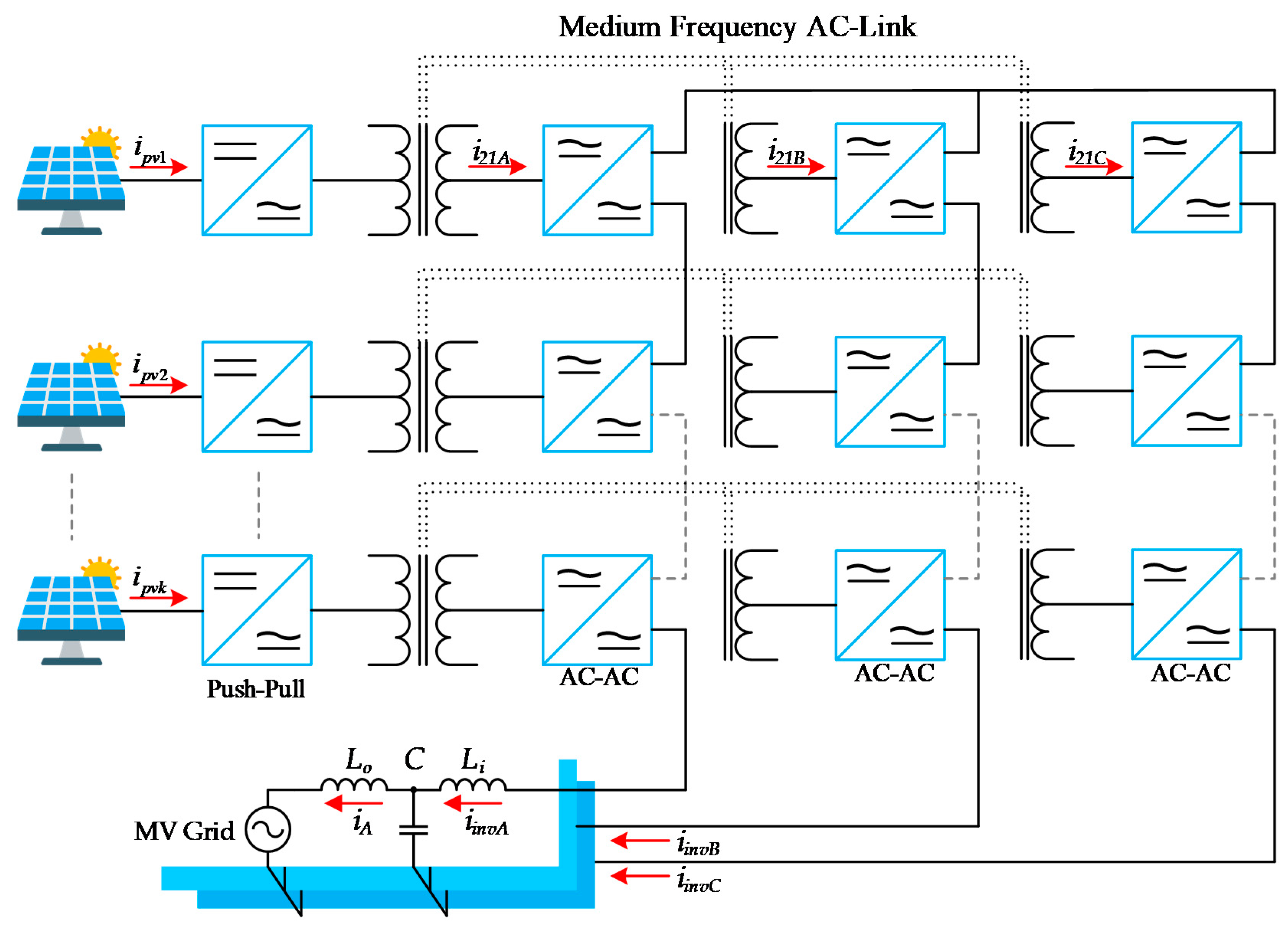
Figure 1. A cascaded three-phase (3PH) DC-AC-AC converter for utility-scale photovoltalic (PV) farm.
Electronics 10 00409 g001
Figure 2. Classic configuration to interconnect PV arrays to the medium-voltage (MV) grid.
Electronics 10 00409 g002
Figure 3. Block diagram of a single-phase DC-AC-AC converter.
Electronics 10 00409 g003
Figure 4. A singles-phase DC-AC-AC converter’s proposal.
Electronics 10 00409 g004
Figure 5. Control scheme of the proposed converter.
Electronics 10 00409 g005
Figure 6. Voltage waveform simulations of the proposed converter. (a) DC source; (b) step-up voltage; (c) multilevel three-phase line-neutral output voltages; and (d) three-phase line-neutral output voltages.
Electronics 10 00409 g006
Figure 7. Main current waveform for the open-loop simulation. (a) DC source; (b) current harmonic spectrum; (c) current waveform through the secondary windings; and (d) line-output current waveforms.
Electronics 10 00409 g007
Figure 8. Main waveforms of the simulation. (a) DC-link voltages; (b) Available versus generated power in the PV; and (c) photovoltaics (PV) currents.
Electronics 10 00409 g008
Figure 9. Main waveforms for closed-loop simulation. (a) Averaged DC-link voltage; (b) current injected to the grid, and (c) inductance-capacitance-inductance (LCL)’s capacitor voltage.
Electronics 10 00409 g009
Figure 10. Photographs of the actual setup for the single-phase five-level DC-AC-AC converter: (a) printed circuit board (PCB) of one single cell and (b) setup for the single-phase two cascaded DC-AC-AC converters.
Electronics 10 00409 g010
Figure 11. Photographs of the actual setup for the three-phase three-level DC-AC-AC converter: (a) PCB of the three-phase DC-AC-AC converter and (b) setup for the three-phase DC-AC-AC converter (from top to bottom: DC-power supply, dSPACE).
Electronics 10 00409 g011
Figure 12. Diagram of the five-level singles phase DC-AC-AC converter.
Electronics 10 00409 g012
Figure 13. Main voltage and current waveforms in a single cell: (a) Channel (Ch)2 primary winding voltage, Ch3 secondary winding voltage, Ch4 VPWM voltage and (b) Ch2 current in the DC-link, Ch3 secondary winding current, Ch4 resistor’s current.
Electronics 10 00409 g013
Figure 14. Experimental results (a,b), Ch3 and Ch4 output voltage, before and after the LC filter respectively, Ch1 output current trough the resistive load, mathematical channel (ChMath) mean output power.
Electronics 10 00409 g014
Figure 15. Block diagram of a three-level three-phase DC-AC-AC converter.
Electronics 10 00409 g015
Figure 16. (a) Waveforms generated in phase A of the three-phase DC-AC-AC converter. Ch1 Output current, Ch2 Line to neutral output voltage before filter, Ch3 Line to neutral output voltage after filter and (b) line-to-line voltages (VPWM) before the filter, Ch1 Phase AB, Ch3 Phase BC, Ch4 Phase CA.
Electronics 10 00409 g016
Figure 17. (a) Line to line voltages (VLL) after the LC filter. Ch2 Phase AB, Ch3 Phase BC, Ch4 Phase CA; (b) Output currents through the three-phase resistive load. Ch1 Phase A, Ch2 Phase B, Ch3 Phase C.
Electronics 10 00409 g017
Table 1. Design parameters of the cascaded 3PH DC-AC-AC converter.
ParameterAcronymValue
Rated PowerPo324.16 kW
Output voltageVLL13.20 kV
DC-link voltageVDC1 kV
Switching frequencyfsw9.96 kHz
Output levelsm7
InductorLi60 mF
CapacitorC100 nF
Line-frequencyf60 Hz
Publisher’s Note: MDPI stays neutral with regard to jurisdictional claims in published maps and institutional affiliations.