Article

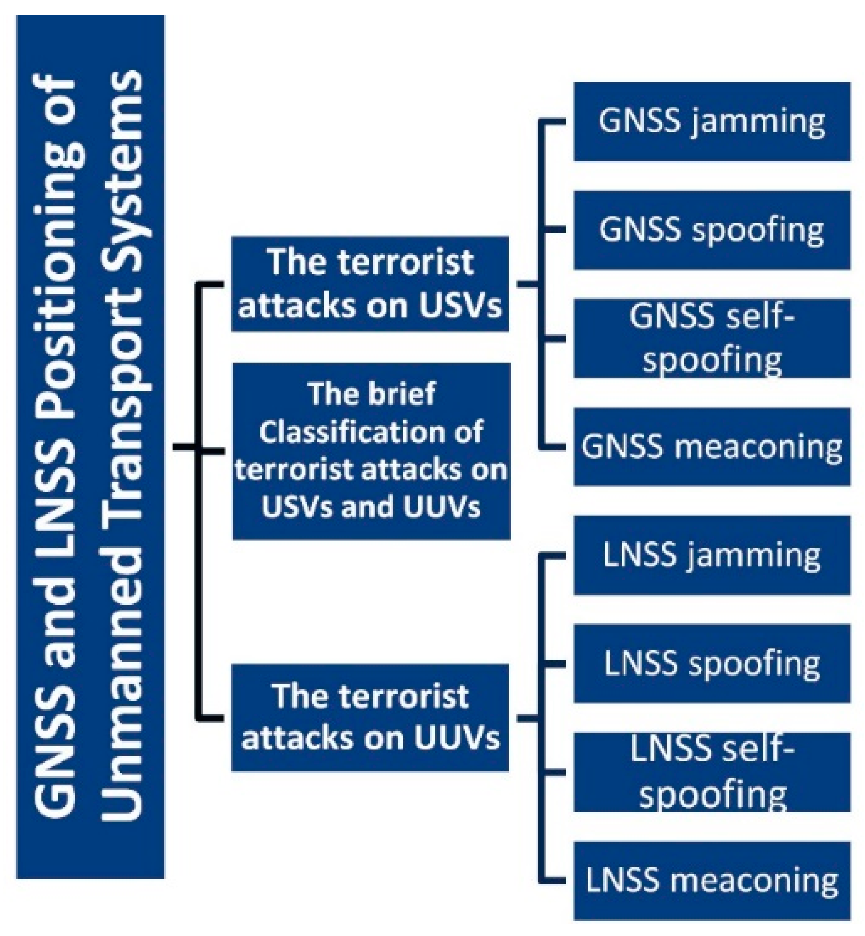
GNSS and LNSS Positioning of Unmanned Transport Systems: The Brief Classification of Terrorist Attacks on USVs and UUVs

by
Łukasz Lemieszewski
1,
Aleksandra Radomska-Zalas
1,
Andrzej Perec
1,*,
Larisa Dobryakova
2 and
Evgeny Ochin
1
1
Department of Technology, The Jacob of Paradies University, 25 Teatralna Street, 66-400 Gorzów Wielkopolski, Poland
2
Faculty of CS & IT, West Pomeranian University of Technology in Szczecin, 17 al. Piastów Street, 70-310 Szczecin, Poland
*
Author to whom correspondence should be addressed.
Electronics 2021, 10(4), 401; https://doi.org/10.3390/electronics10040401
Submission received: 31 December 2020 / Revised: 1 February 2021 / Accepted: 3 February 2021 / Published: 7 February 2021
(This article belongs to the Section Microwave and Wireless Communications)

Abstract

:
As the demand for precision positioning grows around the world and spreads across various industries, initiatives are being taken to increasingly protect Global Navigation Satellite System (GNSS) receivers from intruders of all kinds, from unintentional industrial interference to advanced GNSS spoofing systems. The timing and cost of these forthcoming satellite navigation safety efforts are difficult to decipher due to the large number of new signals and constellations being deployed. However, it is safe to say that the newly designed anti-jamming and anti-spoofing GNSS systems open up new opportunities for innovative technologies. The false acoustic signal delay is equal to the sum of the spoofer receiving antenna delay, processing delay, and propagation delay from the spoofer to the victim. The victim finds the same location as the spoofer’s receiving antenna, and receivers located in different locations will have the same XYZ. The article presents classifications of terrorist attacks of this type.

1. Introduction

“As GPS further penetrates into the civil infrastructure, it becomes a tempting target”.
“Information on the capabilities, limitations, and operational procedures [of spoofers] would help identify vulnerable areas and detection strategies”
[1].
As the demand for precision positioning grows around the world and spreads across various industries, initiatives are being taken to increasingly protect GNSS receivers from intruders of all kinds, from unintentional industrial interference to advanced GNSS spoofing systems. The timing and cost of these forthcoming satellite navigation safety efforts are difficult to decipher due to the large number of new signals and constellations being deployed. However, it is safe to say that the newly designed anti-jamming and anti-spoofing GNSS systems open up new opportunities for innovative technologies.

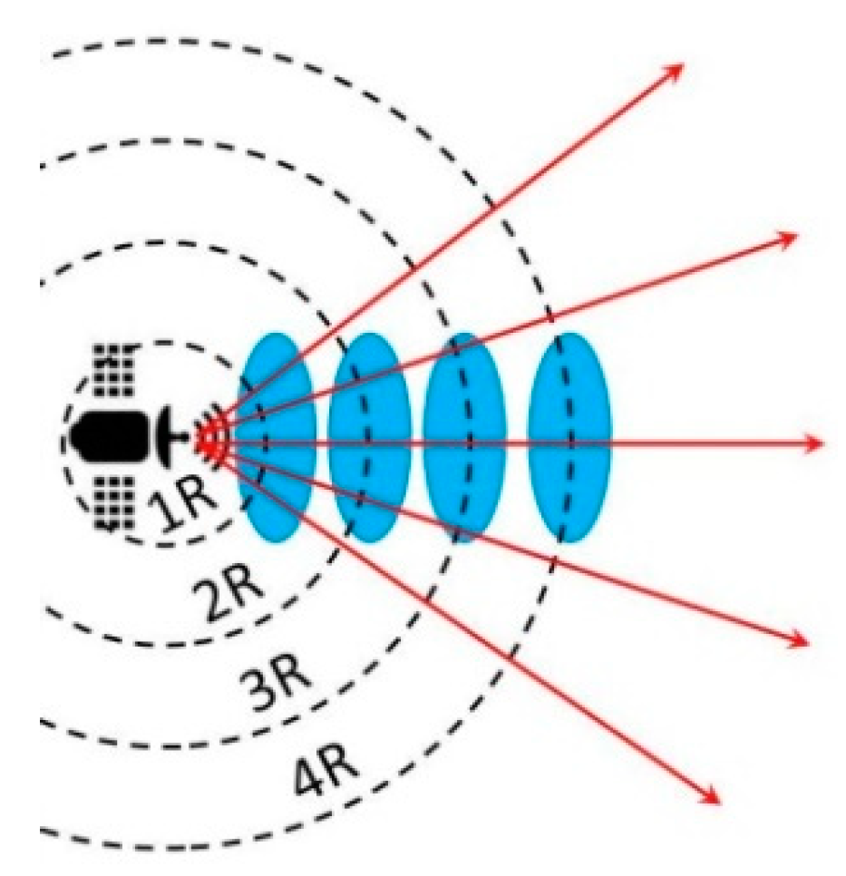
2. The Signal Energy Decreases with Distance from Satellites and Major GNSS Interference Sources

In this article we look at positioning systems in which a navigation receiver “listens” to buoys, receives their messages, and determines a position based on the geographic coordinates of the buoys. Such systems are called Local Navigation Satellite Systems (LNSS). An acoustic signal generator transmits simulated signals from multiple satellites. The receiver of the underwater object “picks up” the false signal and calculates the false XYZ. All receivers in the spoofed area compute the same XYZ.
Unwanted RF signals affecting the USV receiver can be natural, unintentional, or intentional using jammers. GNSS radio signals are hundreds of times weaker than the background noise of radio signals such as VHF, microwave, 3G, Wi-Fi, and Bluetooth (Figure 1), but the introduction of new protocols such as 5G is pushing out GNSS radio signals even more.
The radiated energy of the satellite transmitting antenna decreases when approaching the USV receiving antenna (Figure 2).

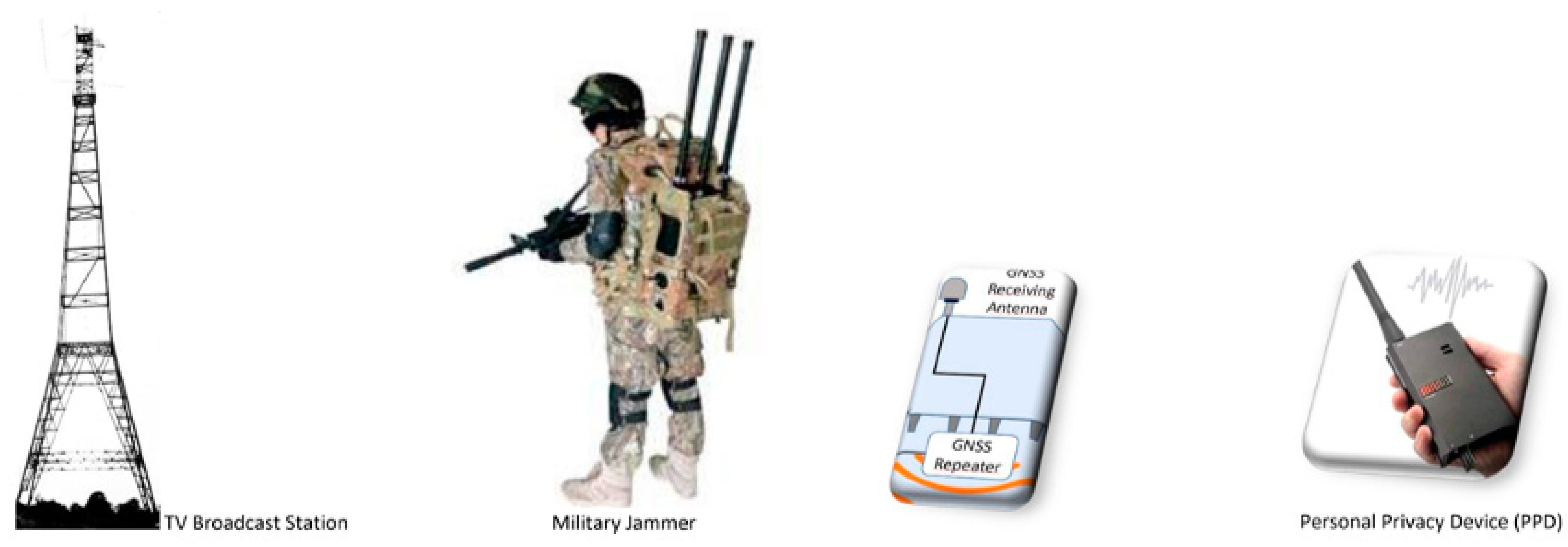
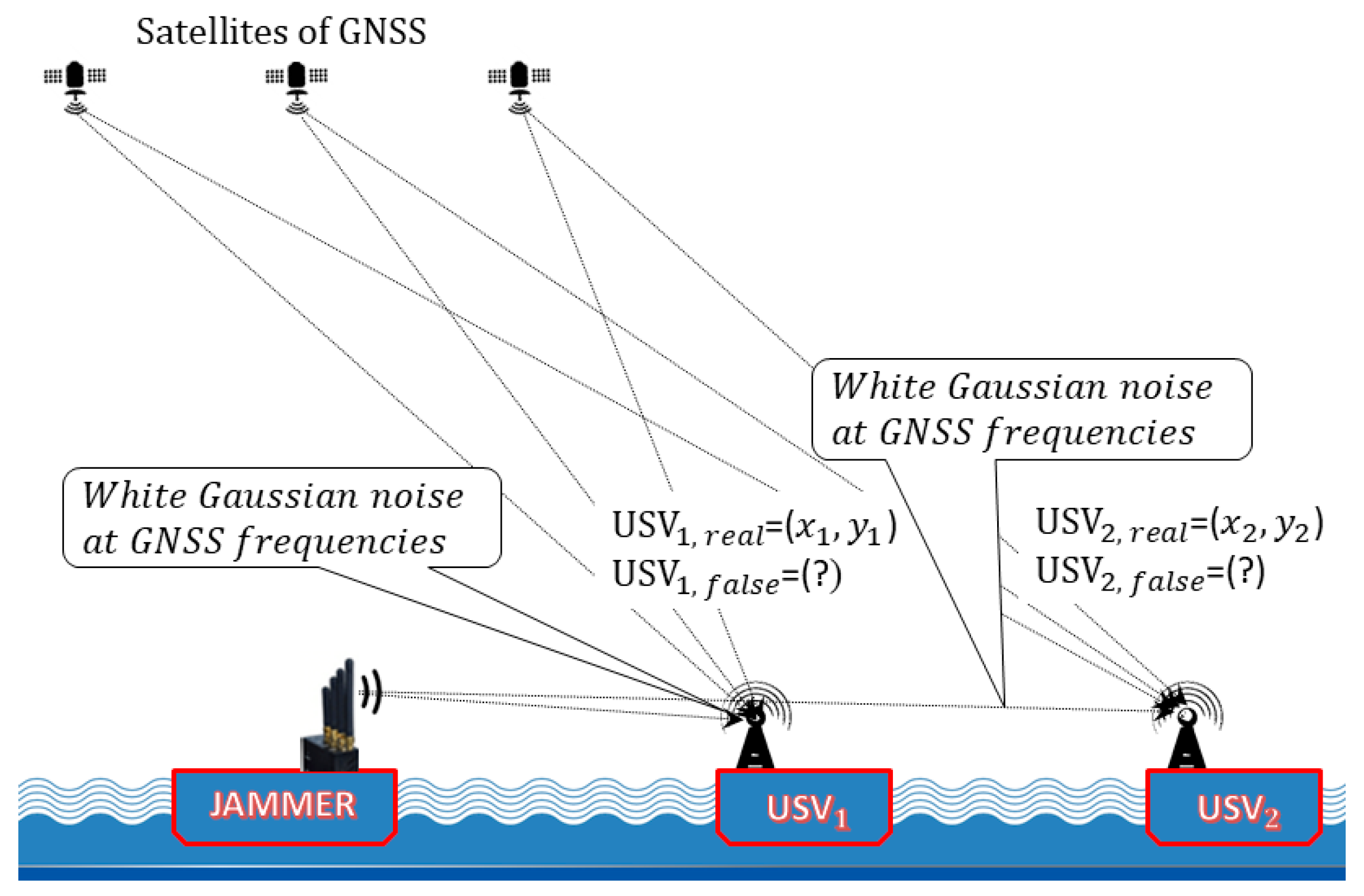
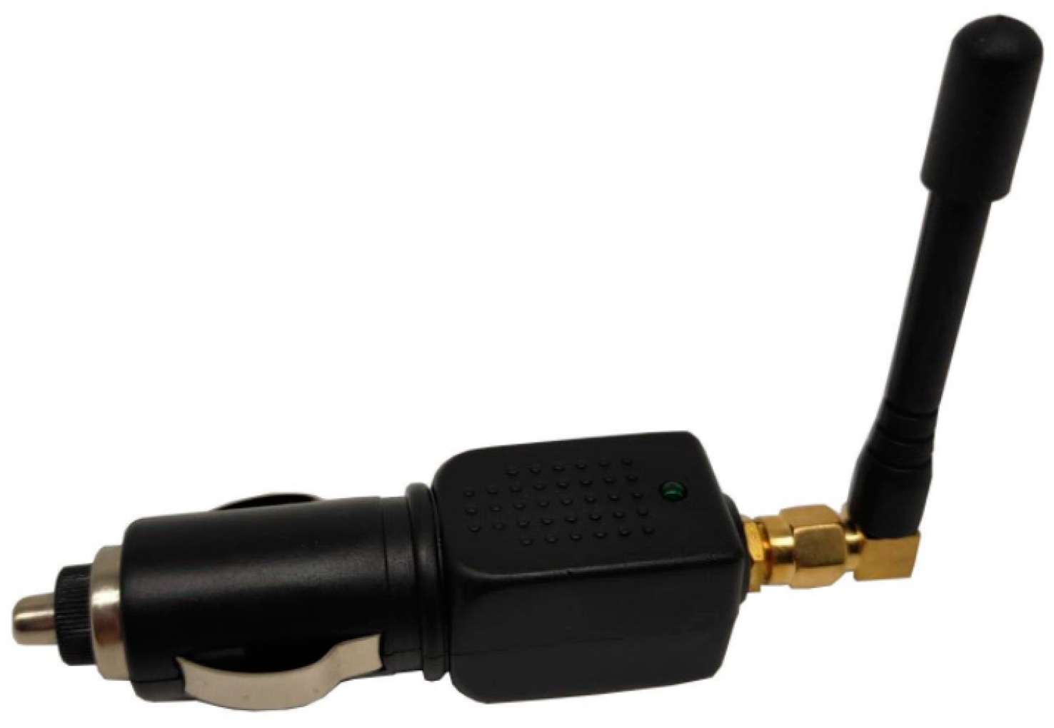
3. The GNSS Jamming as a Terrorist Attack on USVs

Jamming masks and blurs satellite signals with more powerful interference. Thus, the blurry receiver can no longer position itself, or it can position itself erroneously. Although the use of jamming is prohibited, low-power jamming is often used by citizens concerned with protecting their privacy. Drivers who do not want to be monitored also use jamming.
In addition, terrorist use of jamming cannot be ruled out. Powerful jamming systems for GNSS have already been observed in various conflict zones.
For example, the US Navy accidentally disabled GPS for three days at the Port of San Diego in January 2007 [3]. Additional examples are given in [4,5]. A GNSS jamming for USVs (Figure 3) is intentional interference that emits electromagnetic signals at GNSS frequencies in order to jam GNSS signals. Military silencers are widely known, but so-called Personal Protective Devices (PPDs) are becoming more common in everyday practice. PPDs are small, lightweight jammers that are readily available online.
The problem of jamming detection is relatively easy to solve. A detailed explanation of this issue is presented in [6]. Among the many technologies for partial or complete suppression of jamming, we note [7] (Figure 4), which can be bought for under $20.
Interference signals are sent to a spectrum analyzer and an attenuator (VA) is added to the GPS simulator and GNSS signals. VA scales the interference factor.

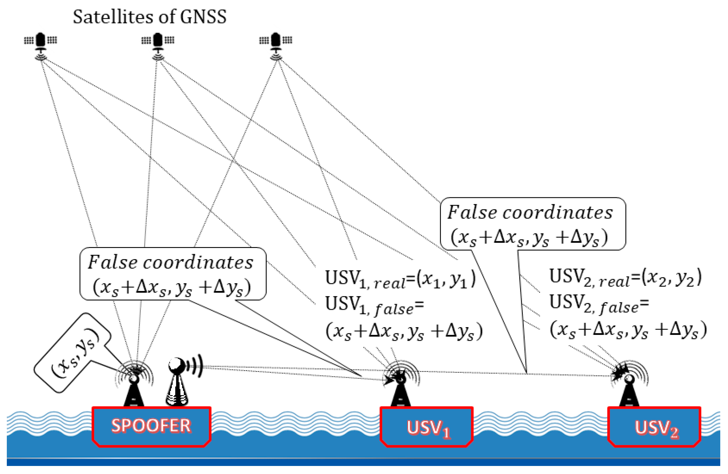
4. GNSS Spoofing as a Terrorist Attack on USVs

One of the earliest high-profile reports was from Iran On 4 December 2011; Iran hijacked an American Lockheed Martin RQ-170 drone (Figure 5) [8], claiming that it had spoofed the GPS.
A GNSS spoofing for USVs (Figure 6) is a system for receiving GNSS signals, introducing some delays into each of the satellite channels, introducing some other signal distortion, and transmitting them on the same frequency, which aims to deceive GNSS receivers and create a false PVT solution. GNSS navigators determine their position with some error, usually known to the spoofer.

5. The Modelling of GNSS Spoofing

The problem of modelling GNSS spoofing is of independent importance. Here we restrict ourselves to considering one of the most advanced simulation systems, namely, SimSAFE (Figure 7) as the comprehensive simulation to protect against GNSS spoofing. SimSAFE represents an innovative way to simulate complex spoofing attacks, proving detection and mitigation measures [9].
The SimSAFE software emulates signal spoofing attacks and test receiver mitigation techniques. SimSAFE allows flexibility in the attack scenario definition and test of interference detection techniques. The tool can be integrated into existing radio navigation testing laboratories, in order to leverage existing hardware such as signal simulators, interference generators, and hardware GNSS receivers.
This technology aims to investigate the effectiveness of GNSS spoofing protection [10,11,12,13,14,15].
The complexity of the anti-spoofing solution problem cannot be overemphasized. See, for example, [16,17,18]. Probably no one has offered anything better than GNSS/INS [19,20]. However, in this case, there is a problem of data integration from multiple sensors [21,22].

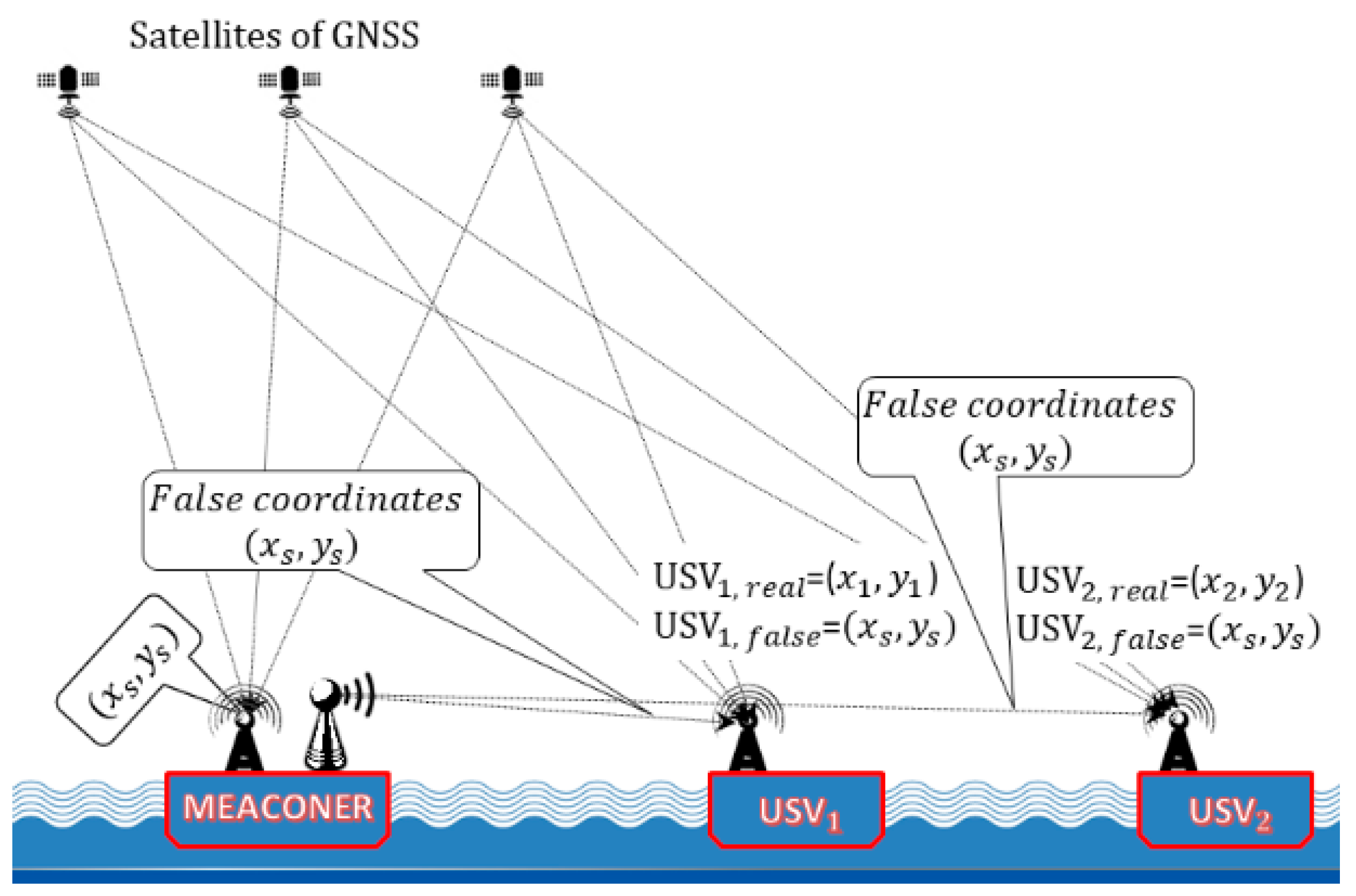
6. The GNSS Meaconing as a Terrorist Attack on USVs

A GNSS Meaconing (the little brother of spoofing in Figure 7) is a system which receives GNSS signals, introducing the same delays into each of the satellite channels (the delay is determined by the difference in the GNSS signal paths from the satellites and from the meaconer to the GNSS navigator antenna), and retransmitting them on the same frequency, which is aimed at misleading GNSS receivers and creating a false PVT solution. i.e., GNSS navigators determine their position with some error, usually known to the spoofer. The properties of such a spoofer have been carefully studied. In particular, the term repeater was often used and is still used today as a synonym for meaconer [23].
A meaconer receives, amplifies, and retransmits radio signals. The spoof signal delay is equal to the sum of the delay at the spoofer’s receiving antenna, processing delay, and propagation delay from the spoofer to the victim. The victim locates the same location as the spoofer receiving antenna. Meaconing is relatively often used for geo-fencing of a some especially dangerous areas or water areas from unmanned technical means. For example, it has reported incidents in the Black Sea that occurred in 2017, when GPS receivers on board more than 20 ships showed the position of Gelendzhik airport [24]. Another well-known example of geo-fencing describes a similar behaviour of GPS receivers in the vicinity of Moscow’s Red Square, which showed the positions of Vnukovo airport [25].

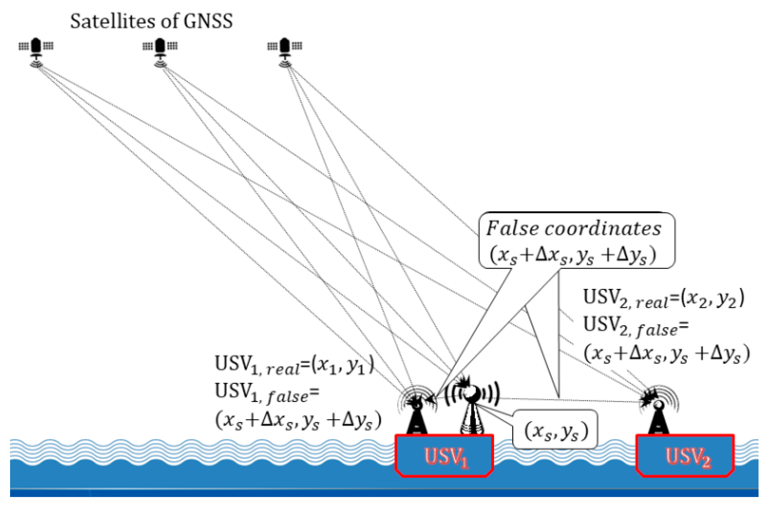
7. The GNSS Self-Spoofing Attack on USVs

A GNSS Self-Spoofing Attack on USVs occurs in situations where the owner of the vehicle wants to hide his/her real position in space for a false one. For example, some USVs are commercial fishing vessels outside of the allowable area and include their own onboard self-spoofer to indicate the position of the USV in the allowable fishing area (Figure 8).
From a technical point of view, the GNSS self-spoofing of USVs is the same spoofing, but here we have an absolutely different way of using spoofing, and if conventional anti-spoofing is based on the choice of technical means to protect oneself from spoofing, then anti-self-spoofing is based on the choice of technical means for attacking this self-spoofing in order to neutralize it, or at least to register the fact of its use by some vehicle including USV.

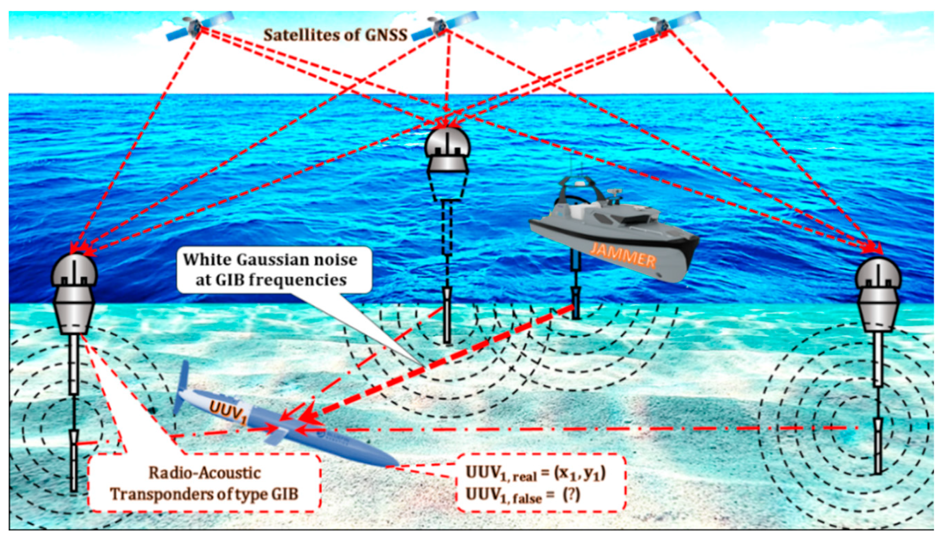
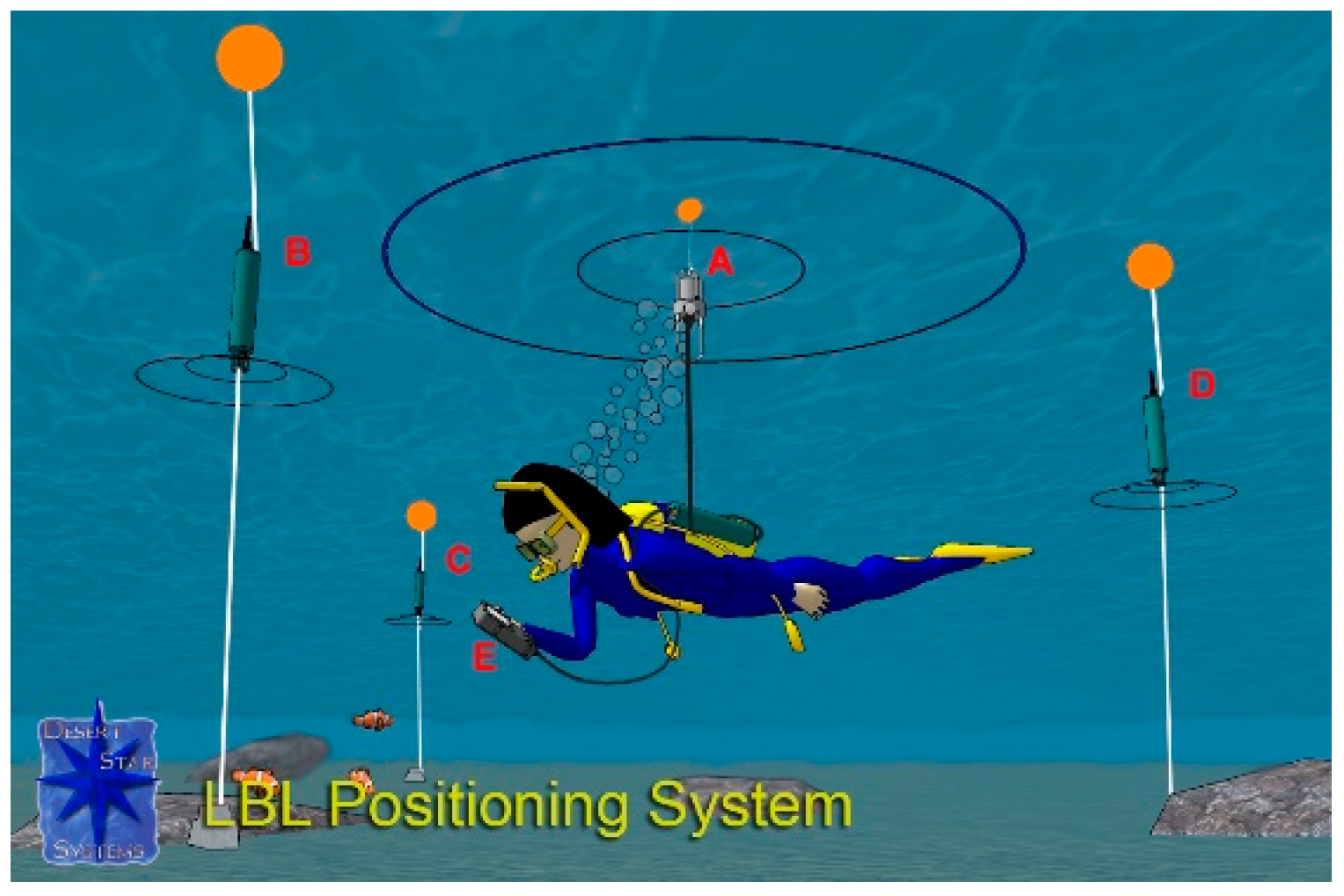
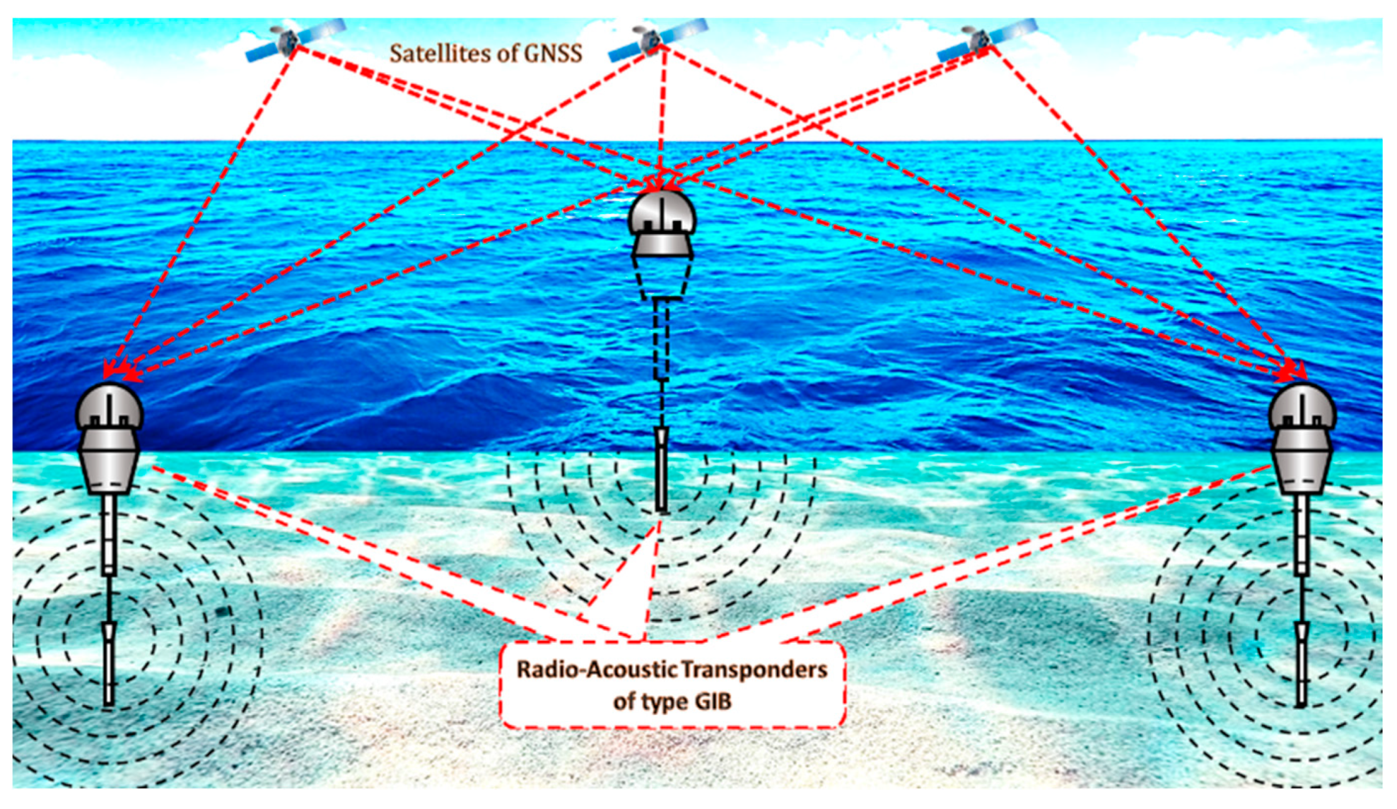
8. The Local Navigation Satellite Systems (LNSS)

Positioning is the most important task of AUV navigation. Navigation Dead Reckoning [19] and INS [20] are traditional methods of localizing and navigating UUVs, but have problems with decreasing position accuracy over time. In addition to traditional technologies, this problem is addressed with acoustic technologies such as LNSS based on Long Baseline (LBL, Figure 9).
Three or more acoustic buoys are placed in a specific area on the ocean surface or along the sides of a ship. The distances between the UUV and the buoys are calculated using signal delays and the speed of sound in the water. The UUV position is calculated using trilateration in the buoy reference frame. The estimated position is transmitted to the parent ship.
Buoys (Figure 10) have three modes of operation. At the first, the product receives information via satellite communication channels, memorizes it and, at the request of the robot, transmits it. In the second mode—“dialogue”—the buoy connects the coastal, aerial, sea control centers with underwater robots over the VHF radio channel in real-time mode. Such data exchange allows not only knowing where the robot is and what tasks it solves, but also to continuously control it. The third mode is the easiest. The robot operates completely autonomously and only checks its coordinates with buoys, adjusting the course. In an emergency, the drone can give an SOS signal, reporting the termination of a deep-sea mission.

9. The LNSS Jamming as a Terrorist Attack on UUVs

A LNSS jamming for UUVs is an intentional interference that emits acoustic signals with a hydrophone at the frequencies of the GNSS radio-acoustic transponders in order to blank out the acoustic GNSS signals (Figure 11).

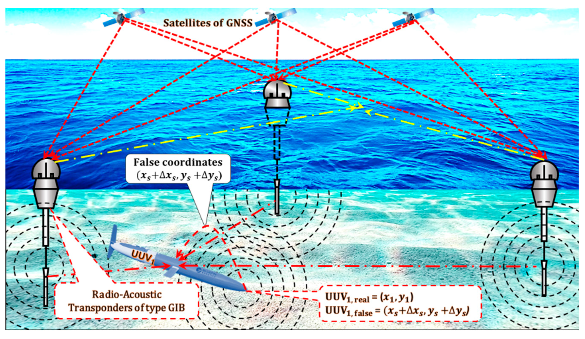
10. LNSS Spoofing as a Terrorist Attack on UUVs

An LNSS spoofing for UUVs (Figure 12) is a system for receiving GIBs signals, introducing some delays into each of the satellite channels, introducing some other signal distortion, and transmitting them on the same frequency, which aims to deceive LNSS receivers and create a false PVT solution. LNSS navigators determine their position with some error, usually known to the spoofer.

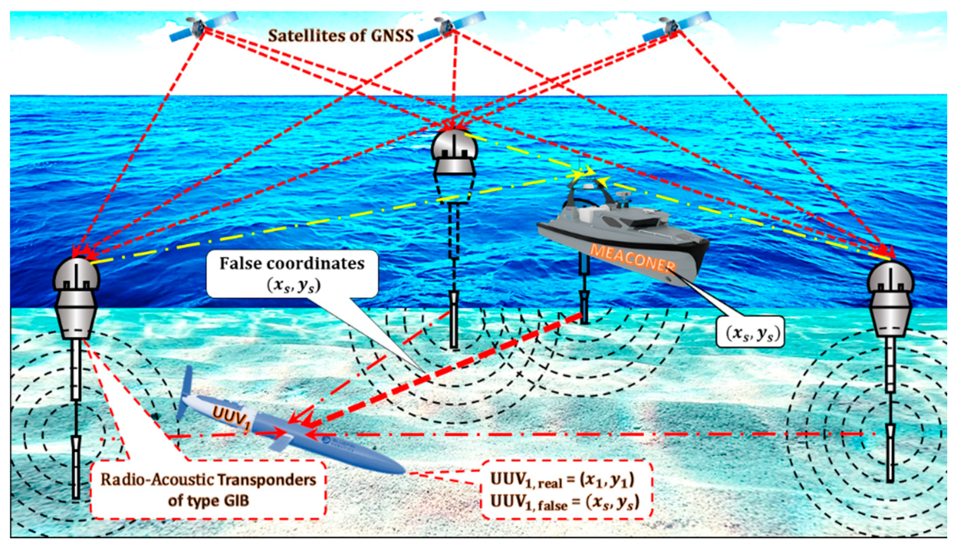
11. LNSS Meaconing as a Terrorist Attack on UUVs

An LNSS meaconing for UUVs (Figure 13) is a system for receiving GIBs signals, introducing some delays into each of the satellite channels, and transmitting them on the same frequency of GIBs, which aims to deceive acoustic receivers and create a false PVT solution. LNSS navigators determine their position with some error, usually known to the meaconer.

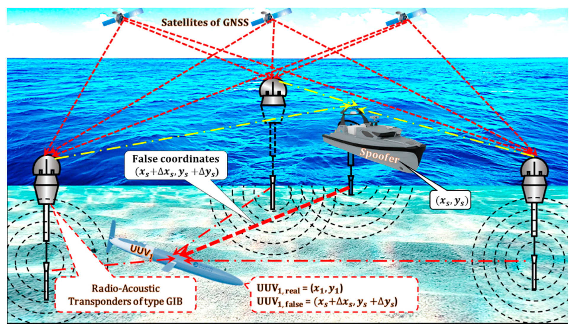
12. The LNSS Self-Spoofing Attack on UUVs

An LNSS Self-Spoofing Attack on UUVs occurs in situations where the owner of the vehicle wants to hide his/her real position in space for a false one. For example, some UUVs are commercial fishing vessels outside of the allowable area and include their own onboard self-spoofer to indicate the position of the UUV in the allowable fishing area (Figure 14).
From a technical point of view, the LNSS self-spoofing of UUVs is the same spoofing, but here we have an absolutely different way of using spoofing, and if conventional anti-spoofing is based on the choice of technical means to protect oneself from spoofing, then anti-self-spoofing is based on the choice of technical means for attacking this self-spoofing in order to neutralize it, or at least to register the fact of its use by some vehicle including UUV.

13. The Brief Classification of Terrorist Attacks on USVs and UUVs

Based on an in-depth analysis of the terrorist attack structures on USVs and UUVs presented here, we present a classification graph (Figure 15).
The analysis of the above structures of the main terrorist attacks showed that at present the terminology in general and for UUVs in particular is not settled. As an example, we will give an ambiguous understanding of the meanings of the words “positioning and localization”. However, the authors hope that the classification given in the article will help systematize the concepts of this section of the navigation safety of unmanned vehicles not only on water, but also, which is extremely important, underwater.

14. Conclusions

Within the framework of this study, it should be emphasized that UUV safety studies are mainly carried out experimentally, as described in detail in the dissertation [26]; at the same time, experimental studies of UUVs safety are associated with the well-known difficulties of deep-sea diving and are mainly limited to modelling.
It is important to emphasize that the conversion of GNSS to LNSS is currently in the early stages of development [27,28,29,30,31].
GNSS is the foundation for USV and UUV positioning. Server-side (cloud-based) methods can play a key role in the provision of GNSS services [32]. In a cloud architecture, access to the encrypted GNSS service is controlled over the communication channel, and the recipient user must authenticate themselves. The main advantage of this approach is its simplicity.

Author Contributions

Methodology and project administration, Ł.L. and A.R.-Z.; validation, A.P. and Ł.L.; formal analysis, L.D. and Ł.L.; funding acquisition, A.P. and A.R.-Z.; software, L.D.; conceptualization and resources, E.O. All authors have read and agreed to the published version of the manuscript.

Funding

This research received no external funding.

Acknowledgments

The authors thank Elżbieta Skorupska-Raczyńska—Rector of The Jacob of Paradies University for help financing this article.

Conflicts of Interest

The funders had no role in the design of the study; in the collection, analyses, or interpretation of data; in the writing of the manuscript, or in the decision to publish the results.

References

  1. 2001 DOT Volpe Report. Available online: https://www.navcen.uscg.gov/?pageName=pressRelease (accessed on 20 December 2020).
  2. GNSS Interference, Safety First. 29 September 2019. Available online: https://safetyfirst.airbus.com/app/themes/mh_newsdesk/pdf.php?p=27033 (accessed on 20 December 2020).
  3. Heue, R. GNSS Jamming and Spoofing: Hazard or Hype? Available online: https://space-of-innovation.com/gnss-jamming-and-spoofing-hazard-or-hype/ (accessed on 20 December 2020).
  4. Axell, E. GNSS Interference Detection. Available online: https://www.foi.se/rest-api/report/FOI-R--3839--SE (accessed on 20 December 2020).
  5. Joo, I.; Sin, C. Design of GNSS jamming propagation simulator using ITU-R P.1546 propagation model. In Proceedings of the 15th International Conference on Control, Automation and Systems (ICCAS), Busan, Korea, 13–16 October 2015; pp. 1359–1362. [Google Scholar]
  6. Axell, E.; Eklöf, F.M.; Johansson, P.; Alexandersson, M.; Akos, D.M. Jamming Detection in GNSS Receivers: Performance Evaluation of Field Trials. J. Inst. Navig. 2015, 62, 73–82. [Google Scholar] [CrossRef]
  7. Anti-Positioning GPS Signal Blocker Car Jammer. Available online: https://pl.gearbest.com/car-gps-tracker/pp_009466526749.html (accessed on 20 December 2020).
  8. Lockheed Martin RQ-170 Sentinel. Available online: https://pl.wikipedia.org/wiki/Lockheed_Martin_RQ-170_Sentinel (accessed on 20 December 2020).
  9. Method of the Operation of a Long Baseline (LBL) Acoustic Positioning System. Available online: https://en.wikipedia.org/wiki/Long_baseline_acoustic_positioning_system (accessed on 20 December 2020).
  10. Schmidt, D.; Radke, K.; Camtepe, S.A.; Foo, E.; Ren, M. A Survey and Analysis of the GNSS Spoofing Threat and Countermeasures. ACM Comput. Surv. 2016, 48, 1–31. [Google Scholar] [CrossRef]
  11. Huang, J.; Presti, L.L.; Motella, B.; Pini, M. GNSS spoofing detection: Theoretical analysis and performance of the Ratio Test metric in open sky. ICT Express 2016, 2, 37–40. [Google Scholar] [CrossRef] [Green Version]
  12. Dobryakova, L.; Lemieszewski, Ł.; Ochin, E. Design and Analysis of Spoofing Detection Algorithms for GNSS Signals. Sci. J. Marit. Univ. Szczec. 2014, 40, 47–52. [Google Scholar]
  13. Ochin, E. Detection of Spoofing using Differential GNSS. Sci. J. Marit. Univ. Szczec. 2017, 50, 59–67. [Google Scholar]
  14. Ochin, E. GNSS and DGNSS Spoofing Detection. Ural. Radio Eng. J. 2017, 1, 55–79. [Google Scholar] [CrossRef] [Green Version]
  15. Dobryakova, L.A.; Lemieszewski, Ł.S.; Ochin, E.F. GNSS Spoofing Detection Using Static or Rotating Single-Antenna of a Static or Moving Victim. IEEE Access 2018, 6, 79074–79081. [Google Scholar] [CrossRef]
  16. Simsky, M. How do We Ensure GNSS Security Against Spoofing? Available online: https://www.gpsworld.com/how-do-we-ensure-gnss-security-against-spoofing/ (accessed on 20 December 2020).
  17. Dobryakova, L.; Lemieszewski, Ł.; Ochin, E. The vulnerability of unmanned vehicles to terrorist attacks such as Global Navigation Satellite System spoofing. Sci. J. Marit. Univ. Szczec. 2016, 46, 181–188. [Google Scholar]
  18. Dobryakova, L.; Lemieszewski, Ł.; Ochin, E. Protecting vehicles vulnerable to terrorist attacks, such as GNSS jamming, by electromagnetic interference shielding of antenna. Sci. J. Marit. Univ. Szczec. 2017, 50, 77–83. [Google Scholar]
  19. Furno. Technology. Dead Reckoning (DR). Available online: https://www.furuno.com/en/gnss/technical/tec_dead (accessed on 20 December 2020).
  20. INS/GPS Inertial Navigation Systems. Accurate Positioning During GPS Outages. Available online: https://gladiatortechnologies.com/insgps/?gclid=CjwKCAiA8ov_BRAoEiwAOZogwUMZ0Dc18lhUer8ibICbC2rm7MSuCJcwWHgKsRgSTlxrAPyew-Y5rRoCdeIQAvD_BwE (accessed on 20 December 2020).
  21. Rodger, J.A. Toward reducing failure risk in an integrated vehicle health maintenance system: A fuzzy multi-sensor data fusion Kalman filter approach for IVHMS. Expert Syst. Appl. 2012, 39, 9821–9836. [Google Scholar] [CrossRef]
  22. Wang, H.; Dong, S. Adaptive Fusion Design Using Multiscale Unscented Kalman Filter Approach for Multisensor Data Fusion. Math. Probl. Eng. 2015, 2015, 854085. [Google Scholar] [CrossRef] [Green Version]
  23. Dobryakova, L.; Ochin, E. On the application of GNSS signal repeater as a spoofer. Sci. J. Marit. Univ. Szczec. 2014, 40, 53–57. [Google Scholar]
  24. Jones, M. Spoofing in the Black Sea: What Really Happened. GPS World. 2017. Available online: http://gpsworld.com/spoofing-in-the-black-sea-what-really-happened/ (accessed on 20 December 2020).
  25. Hans, J. Rund um den Kreml Spielt das GPS Verrückt. Süddeutsche Zeitung. 2016. Available online: https://www.sueddeutsche.de/digital/moskau-lost-in-navigation-1.3228389 (accessed on 20 December 2020).
  26. Lemieszewski, Ł. The Method of GNSS Spoofing Detection in Terms of Transport Safety. Ph.D. Thesis, Maritime Academy in Szczecin, Szczecin, Poland, 2016. [Google Scholar]
  27. Waterston, J. Positioning System for Deep Ocean Navigation (POSYDON). Available online: https://www.darpa.mil/program/positioning-system-for-deep-ocean-navigation (accessed on 20 December 2020).
  28. Osborn, K. DARPA Discovers “GPS-Like” Undersea Drone Connectivity. Available online: https://defensesystems.com/articles/2017/02/14/darpauuv.aspx (accessed on 20 December 2020).
  29. Ochin, E. The spoofing detection of Underwater Acoustic GNSS-like Positioning Systems. Sci. J. Marit. Univ. Szczec. 2019, 57, 38–46. [Google Scholar]
  30. Abramowski, T.; Bilewski, M.; Dobryakova, L.; Ochin, E.; Uriasz, J.; Zalewski, P. Safety of GNSS-Like Underwater Positioning Systems. Available online: https://www.preprints.org/manuscript/201909.0052/v1 (accessed on 20 December 2020).
  31. Abramowski, T.; Bilewski, M.; Dobryakova, L.; Ochin, E.; Uriasz, J.; Zalewski, P. Detection of Spoofing Used against the GNSS-Like Underwater Navigation Systems. Available online: https://www.preprints.org/manuscript/202001.0187/v1 (accessed on 20 December 2020).
  32. Dobryakova, L.; Lemieszewski, Ł.; Ochin, E. Cloud-based GNSS Navigation Spoofing Detection. Sci. J. Marit. Univ. Szczec. 2019, 57, 29–37. [Google Scholar]
Figure 1. Main known sources of GNSS interference [2].
Electronics 10 00401 g001
Figure 2. The signal energy decreases with distance from the satellite.
Electronics 10 00401 g002
Figure 3. The basic GNSS jamming scheme of USVs: at some point in time, the jammer transmits white noise at GNSS frequencies, which aims to make a PVT solution impossible. All USVs in the jammed area lose orientation.
Electronics 10 00401 g003
Figure 4. Typical illegal in-car chirp jammer (aka Personal Privacy Device or PPD) [7].
Electronics 10 00401 g004
Figure 5. Iran hijacked Lockheed Martin RQ-170 Sentinel drone (The reporting of this incident led to a change in the topic of Łukasz Lemieszewski’s dissertation and to the defence of Poland’s first dissertation “The method of GNSS spoofing detection in terms of transport safety”) [8]. General characteristics: Length: 8 ft 7 in (4.5 m), Wingspan: 38 ft (12 m), Height: 6 ft (1.8 m).
Electronics 10 00401 g005
Figure 6. The basic GNSS spoofing scheme of USVs: at some point in time, the spoofer determines its position ( x s ,   y s ) , introducing some delays into each of the satellite channels, introducing some other signal distortion, and transmitting the false position ( x s ,   y s ) on the same frequency, which aims to deceive GNSS receivers and create a false PVT solution. All USVs in the spoofer activation zone are positioned as USV i ,   f a l s e = ( x s + Δ x s ,   y s   + Δ y s ).
Electronics 10 00401 g006
Figure 7. The basic GNSS meaconing scheme of USVs: at some point in time, the meaconer determines its position ( x s ,   y s ) , introducing some delays into each of the satellite channels, and transmitting the false position ( x s ,   y s ) on the same frequency.
Electronics 10 00401 g007
Figure 8. The basic GNSS self-spoofing scheme of USVs: at some point in time, the self-spoofer determines its position ( x s ,   y s ) , introducing some delays into each of the satellite channels, introducing some other signal distortion, and transmitting the false position ( x s + Δ x s ,   y s + Δ y s ) on the same frequency, which aims to deceive GNSS receivers and create a false PVT solution. All USVs in the self-spoofer activation zone are positioned as USV i ,   f a l s e   =   ( x s + Δ x s ,   y s   + Δ y s ).
Electronics 10 00401 g008
Figure 9. Method of the operation of a long baseline (LBL) acoustic positioning system [9].
Electronics 10 00401 g009
Figure 10. The main idea of LNSS.
Electronics 10 00401 g010
Figure 11. The LNSS basic jamming scheme of UUVs: at some point in time, the jammer transmits white noise at GIB frequencies, which aims to make a PVT solution impossible. All UUVs in the jammed area lose orientation UUV false = (?).
Electronics 10 00401 g011
Figure 12. The basic spoofing scheme of UUVs: at some point in time, the spoofer determines its position ( x s ,   y s ) , introducing some delays into each of the GIBs channels, introducing some other signal distortion, and transmitting the false position ( x s ,   y s ) on the same frequency of GIBs, which aims to deceive acoustic receivers and create a false PVT solution. All UUVs in the spoofer activation zone are positioned as UUV i , false = ( x s + Δ x s ,   y s + Δ y s ).
Electronics 10 00401 g012
Figure 13. The basic LNSS meaconing scheme of UUVs: at some point in time, the meaconer determines its position ( x s ,   y s ) , introducing some delays into each of the satellite channels (the delay is determined by the difference in the GIBs signal paths from the GIBs and from the meaconer to the UUV navigator antenna) and transmitting the false position ( x s ,   y s ) on the same frequency of GIBs, which aims to deceive acoustic receivers and create a false PVT solution. All UUVs in the meaconer activation zone are positioned as UUV i , false   =   ( x s ,   y s ).
Electronics 10 00401 g013
Figure 14. The basic LNSS self-spoofing scheme of UUVs: at some point in time, the self-spoofer determines its position ( x s ,   y s ) , introducing some delays into each of the satellite channels, introducing some other signal distortion, and transmitting the false position ( x s + Δ x s ,   y s + Δ y s ) on the same frequency, which aims to deceive GIB receivers and create a false PVT solution. All UUVs in the self-spoofer activation zone are positioned as UUV i , false = ( x s + Δ x s ,   y s + Δ y s ).
Electronics 10 00401 g014
Figure 15. The classification of terrorist attacks on USVs and UUVs.
Electronics 10 00401 g015
Publisher’s Note: MDPI stays neutral with regard to jurisdictional claims in published maps and institutional affiliations.

