Abstract
Multilevel inverter had been paid a lot of attention from the academia and research community in recent times due to its role in high and medium power applications. In this paper, a detailed survey is made on the recently designed multilevel inverter to find the suitability of the inverters for particular applications. Research is performed on various types of multilevel inverters such as: Symmetric, asymmetric, hybrid and modularized multilevel inverter in order to identify the issues in generating more levels at the output. A summary of various issues in multilevel inverter with reduced switch count is provided, so that a novel topology of multilevel inverter can be designed in future. Further, an 81-level switched ladder multilevel inverter using unidirectional and bidirectional switches is designed. Simulation work is carried out using Matlab/Simulink in order to validate the performance of the inverter with change in resistive load and impedance load. The output of the 81-level inverter is fed to a 110 V, 186.5 W single phase induction motor in order to study the characteristics, further speed control of motor is performed by varying the input voltage of the motor and the results are presented.
1. Introduction
Nowadays, multilevel inverters (MLI) play a major role in various power applications such as Electric Vehicle [1], Photovoltaic systems [2], Low-Power Loads [3], Grid integration system [4]. It is more attractive because of very low harmonic distortion, low number of drivers, absence of filters, low installation area, reduction in voltage stress and switching losses.
A generalized cascaded multilevel inverter is presented with nearest level modulation technique. The proposed converter is discussed with and without half bridge circuits [2]. A new multilevel inverter with one DC source is presented for low power applications. The proposed inverter generates the output voltage eight times higher than the input voltage [3]. In [4], various configurations of MLI’s were analyzed in terms of number of switching devices and modulation techniques. MLI are broadly classified into cascaded H Bridge, neutral clamped and flying capacitor topologies [5].
Recently, for hybrid systems cascade multilevel inverters are applied. Many topologies are there to create the staircase voltages with higher levels with low devices count [6]. A new MLI is designed to generate generate 27-level and fifty one level output voltages using constant voltage sources for resistive-inductive load [7]. An inverter is designed using trinary DC sources and thirteen switches to generate 53 output levels with minimum THD of 1.15% [8]. A new switched source MLI is proposed which operates under both symmetric and asymmetric mode. The proposed inverter is designed with six power switches and two voltage sources [9]. A new 81-level MLI is presented using two stage ladder circuits and the values of the dc sources are fixed by two different algorithms. The presented topology is tested with resistive and impedance load [10]. A cascaded MLI is presented to generate 9, 15, 27, 33 and 39 output voltage levels at the load. It is observed that increase in number of voltage levels reduces the presence of harmonic content in load voltage and current waveforms. The proposed inverter is simulated in Matlab/Simulink and analyzed the total harmonic distortion for resistive and resistive-inductive load [11]. Various configurations of symmetrical, asymmetrical and hybrid MLI’s were synthesized in terms of number of switches, capacitors, diodes utilized in the inverter circuit. As well, an analyzes is made in terms of THD generation and total standing voltages of all the configurations [12]. Few drawbacks such as: switch count, voltage imbalance and number of DC sources are there in all the topologies [13].
Multilevel inverter with minimum switch count is focused nowadays with higher voltage levels [14]. Higher voltage levels are attained using cascaded H bridge MLI with isolated DC voltage sources. The switch count reduction is based on the design of basic unit. MLI with three phase is proposed with reduced power switches and has attained nine output voltage levels. The proposed structure is analyzed for various pulse width modulation (PWM) techniques. Total harmonic distortion is examined for all the PWM techniques [15].
A new optimized structure of MLI is designed to create a rectangular type and circular type with a smaller number of switching components. A new switching technique is adopted and it is validated through simulation and experimental studies [16]. A three phase cascade H bridge (CHB) inverter is proposed with discontinuous pulse width modulation which reduces switching losses and thus increases the lifetime of the switches. MLI also adopted with rotation scheme for even distribution of power in the switches [17]. A trinary CHB MLI is proposed for solar power system with equal number of voltage levels.
For the control of active power and grid interaction, a modified second order integral control is applied [18]. The space vector pulse width modulation scheme is being applied to the MLI for common mode voltage reduction [19]. Two new MLI structures are designed and interfaced with PV system. Both the MLI structures consists of equal number of power switches and generates 9-level output [20].
This paper consists of six sections including introduction. Section 2 discussed about the survey on multilevel inverter with reduced switch (MLIRS) designs, Section 3 discussed the issues related with the construction of MLIRS, Section 4 discussed proposed MLI topology, design parameters of switched ladder inverter and generation of 81-levels and Section 5 presented pulse generation logic and analysis of results.
2. Survey on MLIRS Designs
For a medium voltage high power single phase application, a fifteen level inverter is designed using three DC sources and ten switches. Further, the design topology is modified to generate 25-levels at the output using four DC sources and twelve switches. By comparing the two inverter design, the extended topology utilized fewer switches to generate more output levels. Nearest level control method is applied to generate pulse for the switches and this inverter works with symmetrical and asymmetrical configurations [21].
To attain the speed torque characteristics of AC motor under loaded conditions, a seven level inverter is designed using seven power switches and three voltage sources. The advantages of using this inverter in medium voltage drives are reduction in the size of filter and low voltage stress [22].
A 17-level inverter is designed using unidirectional and bidirectional switches with four asymmetric sources which varies in trinary fashion. The designed topology is tested with impedance load and found to be usage of minimum number of switches to generate more output levels [23].
A 17-level inverter with reduced power switches for open end induction motor drives is proposed. A level shifted carrier scheme is applied for v/f and d/q control for induction motor drives. The circulating power is analyzed and eliminated by space vector analysis. The proposed topology is suitable for traction and induction motor drive application [24].
A multilevel inverter is proposed with fuel cell and attains high output levels. Using MATLAB simulation is completed with less power electronic switches to obtain output voltage levels such as: 5, 7 and 15-levels. Through mathematical calculation efficiency and power loss is analyzed. Switching loss, device stress and driver circuits are compared with other multilevel inverter topologies [25].
A 9-level and 49-level multilevel inverter is proposed and simulated [26]. The basic structure consists of two voltage sources and five switches. The harmonic distortion achieved for a 9-level inverter is 9.85% and for a 49-level inverter is 2.01%, it is found that increase in output voltage levels leads to reduction in harmonic content at the load [26]. A ‘T’ type multilevel inverter is proposed for transformer less DVR with reduced switches. The basic structure consists of eight switches which generates five level output voltage using two DC sources. This designed inverter regulates the load voltage under sag condition, but this topology requires high power rated switches [27].
With no additional components such as inductor and capacitor, a new multilevel inverter is proposed. The proposed structure operates on symmetric and asymmetric mode. MATLAB simulation is done for constructing 79-levels and 321-levels. The proposed multilevel inverter is operated for grid utility from renewable energy sources [28].
Cascaded H bridge multilevel inverter contains a greater number of switching devices and sources. A new 9-level multilevel inverter in cascaded transformer is proposed with minimum number of switching devices and DC supply. Conventional cascaded transformer based 9-level MLI is compared with proposed 9-level MLI. The performance is analyzed and tested for multi carrier PWM technique [29].
A new MLI with hybrid structure is proposed. Selective harmonic elimination technique is applied to obtain the quality in the output voltage with reduction in lower order harmonics. The proposed topology is analyzed for R and RL loads [30]. High voltage stress occurs in two stage switched capacitor multilevel inverter. To overcome this problem single stage switched capacitor multilevel inverter is proposed. The basic unit consists of twelve switches with only one DC source. The proposed topology is tested experimentally [31]. Low total standing voltage is achieved by multi-unit MLI with single phase supply using minimum number of switching components. The proposed structure is compared with existing MLI units under varying loaded conditions [32]. Various configurations of cascaded half bridge inverter applied for grid tied PV system is discussed in terms of control methodologies. The performance of CHB inverter is validated in all the aspects [33]. The various applications of MLI are shown in Table 1.

Table 1.
Applications of MLI with reduced switches.
Output voltage level generated with respect to the number of switches used for various topologies is tabulated in Table 2.
Table 2.
Number of switches versus Number of Levels.
3. Issues in MLI with Low Device Count
In MLI, there are issues such as: Voltage unbalancing, gate pulse generation and circuit complexity. The major issues in various MLI topologies are discussed in Table 3. Some of the challenges are discussed below. In [20] additional power stage is used, a transformer along with the inverter which increases the cost. Reactive power capability is absent in the structure proposed in [20]. The design structure presented in [21,22] requires a greater number of components for constructing higher number of levels. The design topology in [23] uses bidirectional switches which increases the cost and size of the inverter. The inverter topology in [24,25] utilizes more circuit components to generate higher output voltage levels. The reduction of harmonic content in the output load waveform is challenging and it is presented in [26]. Inverter proposed in [27] has higher total standing voltages. The presented topology in [28,29] requires more circuits to achieve more output levels. A complex control is necessary in-order to design a bi-direction MLI [30]. Voltage balance in the capacitor is challenging in the switched capacitor MLI with reduced switch count [31]. Balancing the voltage in DC link needs high attention [32]. The configuration presented in [33] utilizes more switches to generate higher number of voltage levels. In [34], the basic structure of proposed system requires two bidirectional switches and it is used to generate 17-levels in the output via asymmetrical configuration. In order to increase the output levels by cascading the SLMLI unit or increasing the ladder structure that is ‘m’, the total voltage appeared across the switches Sx and Sy is becoming high and it increases the rating of the devices. Furthermore, the switching frequency is high to generate desired output levels which increases switching losses.
Table 3.
Issues in MLIRS.
In [35], various topologies of MLI were designed using higher number of voltage sources with less number of switches to achieve more output voltage levels and the issues found in the configurations are listed in Table 2. In [36,37], a symmetric multilevel inverter is designed and found failure in the implementation of medium and high voltage applications. In [38,39], a multilevel inverter is designed using asymmetrical voltage sources to generate more output voltages levels with increase in the number of switches. A hybrid MLI designed with complex control technique and it is presented in [40].
In [41], the proposed system is used to generate 9-levels in the output with four dc sources, eight switches and four diodes. While extending the output voltage levels, more units are added and thus conduction and switching losses are more. In addition to increase in switching loss, stress across the switch is increasing.
Circuit proposed in [42] consists of single source and double sources configuration to build multi levels in the output by connecting the sources in series and parallel. For this configuration there is a possibility of short circuit of DC sources while turning on the sources and voltage stresses between the switches is high. A Cascaded switched diode MLI is designed utilizing more number of diodes [43].
In [44], proposed cascaded switched diode structure consists of two stages. First stage contains dc sources, switch and diode. The second stage is an H-bridge inverter, in order to increase the multilevel in the output, number of units in the first stage is increased and thus large number of switches and diodes are required.
Conventional diode clamped and capacitor clamped multilevel inverters [45] are modified by adding single phase full bridge inverter. This proposed system reduces the number of switches but the requirement of diodes and capacitors are increased compared to the conventional inverters.
Significant factors of inverter design using Asymmetric voltage sources presented in [46] is identified and tabulated in Table 2. As well, few of the challenges in the reduced switch MLI [47], Asymmetric MLI [48] and modularized MLI [49] were identified and listed in Table 2.
In [50], 9-levels of output voltage are generated using 12 numbers of switches and 4 number of dc sources. In order to construct each level of output waveform, six switches are required to be turned on at an instant and thus switching losses are increasing. A 9-level symmetric and 31 level asymmetric inverter were simulated using a smaller number of voltage sources [51]. Using large number of switches, a symmetric MLI topology is designed and experimented in [52]. Also various topologies of MLI were designed using optimal number of switches [53,54,55,56,57].
4. Design of Proposed Cascaded SLMLI to Generate 81 Level
In the proposed work, switched ladder inverter is designed to generate 81 output voltage levels. Figure 1a is a generalized structure of SLMLI. Number of output levels can be increased by either increasing the magnitude of dc sources as shown in Figure 1b or by cascading a number of stages by fixing dc sources in each stage.
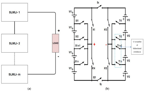
Figure 1.
(a) Generalized structure of SLMLI [34]; (b) proposed SLMLI [34].
In order to increase the number of levels further, using proposed switched ladder inverter, it leads to increase the component count which makes the system bulky, costly, and complex. As well, the voltage rating on the switches of Sx and Sy is equal to the sum of all sources values. To reduce the number of used components and voltage on Sx and Sy, cascade topology based on series connection of ‘m’ SLMLIs is recommended which is presented in Figure 1b. Proposed structure is named as cascaded switch-ladder inverter (CSLMLI). The output voltage of SLMLI (Vout) is equal to the sum of output voltages of all the SLMIs and it is given in Equation (1).
where Vo1, Vo2 and Vom are the output voltage produced by stage-1, stage-2 and stage-m respectively.
Vout = Vo1 + Vo2 + … + Vom.
The voltage levels at the output are achieved by considering the quantity of bidirectional switches in each SLMLI and it is given by:
The generalized structure shown in Figure 1 consists of unidirectional and bidirectional switches.
2z1 = 2z2 = … = 2zb= 2z
4.1. Design Parameters Cascaded SLMLI for Two Stages
The SLMLI design parameters are determined by using two methods and both methods are explained as follows.
Method 1:In this method, necessary expressions are given below:
The maximum output voltage, level generation, switches and sources required are calculated as follows:
where z is the number of bidirectional switches in each ladder structure.
V1 = V3 = Vdc
V2 = V4 = (z + 2) × Vdc
Vcascaded,max = 2 × [(z + 1) × (V1 + V4)]
Nlevel = 2 × [(Vcascaded,max)/V1] + 1
Nswitch = 4 × (2z + 3)
Nsource = 4 × (z + 1)
Method 2:In this method, V3 and V4 values are computed and it is mentioned as follows:
The maximum output voltage, level generation, switches and sources required are represented as follows:
V1 = Vdc
V2 = (z + 2) × Vdc
V3 = (4z) × V1
V4 = (z + 2) × V3
Vcascaded,max = (2) × (V1 + V2 + V3 + V4)
Nlevel = 2 × [(Vcascaded,max)/V1] + 1
Nswitch = 2 × (4z + 6)
Nsource = 4 × (z + 1)
4.2. Cascaded SLMLI to Generate 81 Levels (2-Stages)
Inverter shown in Figure 1b is used to generate ‘n’ number of levels, but the rating of switches is increasing with the increase in magnitude of voltage. This problem is solved by cascading number of switch ladder multilevel inverters to generate ‘n’ number of output levels. Figure 2 shows the circuit diagram of cascaded SLMLI to generate 81 levels in the output voltage.
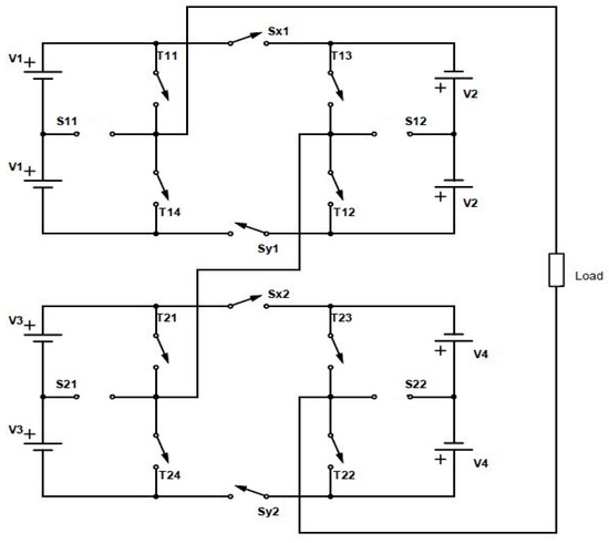
Figure 2.
Cascaded two stages of SLMLI.
Stage-1 requires the same number of switches and sources that used in stage-2 In stage-1, unidirectional switches are represented as T11, T12, T13, T14, SX1, SY1 and the bidirectional switches are shown as S11, S12. In stage-2, unidirectional switches are mentioned as T21, T22, T23, T24, SX2, SY2 and the bidirectional switches are shown as S21, S22. By cascading two stages, the voltage stress between the switches and dv/dt are reduced and hence it reduces overall cost. Table 4 shows the switching sequence for the proposed SLMLI.
Table 4.
Switching sequence for the Proposed SLMLI.
5. Pulse Generation and Simulation Results
In order to construct multiple voltage levels in the load side, proper generation of pulses is needed. Figure 3 explains the method to generate pulses for the inverter. Pulses are generated by comparing a sinusoidal wave with the constant voltage steps at regular intervals. Switching state will become one when sinusoidal is in between ith level and i + 1th level. For 81 level generation, value of ‘i’ will be varying from 0 to 41 to construct positive 41 levels and same will be repeated for negative also. Adder will combine all the switching states created and it will act as an input to activate the corresponding switching pattern via a multiport switch. De-multiplexer is used for distributing the pulses for the inverter. Based on the switching sequence shown in Table 4 the pulses will be given to appropriate switches. In the Table 4, the ON condition and OFF condition of the switches are represented as δ and ø respectively.
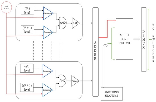
Figure 3.
Block diagram for pulse generation.
Figure 4 shows the block diagram for generating 81 levels and Figure 2 represent the structure of SLMLI. Pulse generator (Figure 3) is used for creating pulses for all the switches located in the two stages.
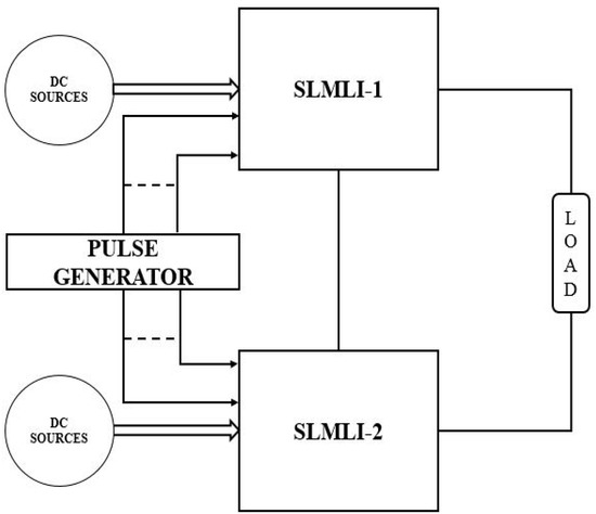
Figure 4.
Block diagram of SLMLI.
Figure 5a,b shows the pulse waveforms for one cycle of switches in stage-1 and stage-2 respectively to generate 81 levels.
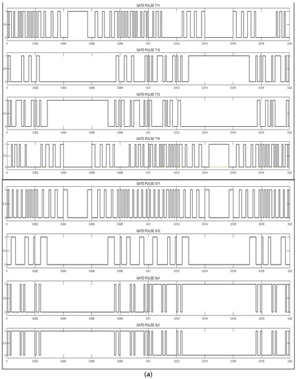
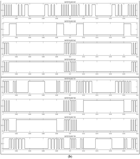
Figure 5.
(a) Pulse waveforms for stage-1; (b) pulse waveforms for stage-2.
The magnitude of the direct current voltage sources in switched ladder multilevel inverter stage-1 are selected as V1 = 5 V and V2 = 15 V. For the stage-2 switched ladder multilevel inverter the amplitude of the voltage sources is selected as V3 = 20 V and V4 = 60 V. The proposed topology is simulated for grid frequency 50 Hz and the parameters of the sources voltages and load values are given in Table The magnitude of the direct current voltage sources in switched ladder multilevel inverter stage-1 are selected as V1 = 5 V and V2 = 15 V. For the stage-2 switched ladder multilevel inverter the amplitude of the voltage sources is selected as V3 = 20 V and V4 = 60 V. The proposed topology is simulated for grid frequency 50 Hz and the parameters of the sources voltages and load values are given in Table 5.
Table 5.
Specification of two stage SLMLI.
The 81 level inverter output voltage and output current waveform is shown in Figure 6. The resistive load is tested for four cycles (i.e., 0.08 s). The inverter is tested with resistive load of 10 Ω for the first cycle (i.e., 0.02 s), during this period the output load current is observed as 20 A. For the second cycle (i.e., from 0.02 s to 0.04 s) the inverter is connected with 5 Ω resistance and obtained the load current as 40 A. For the third and fourth cycle (i.e., from 0.04 s to 0.08 s), the inverter is connected with load resistance of 2.5 Ω to produce 80 A at the load. For these entire instances, the peak load output voltage is observed as ±200 V.
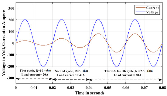
Figure 6.
Output voltage and change in current waveforms for variable R load.
The harmonic content present in the output voltage and current waveforms are obtained from FFT (Fast Fourier transform) analysis are 1.18% and it is shown in Figure 7a,b.
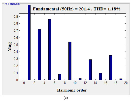
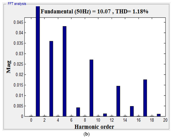
Figure 7.
(a) FFT for output voltage fed with R load; (b) FFT for output current fed with R load.
Figure 8 shows the output voltage and variation in the current waveform for the change in impedance load at equal interval of time. For Z = 10.12 Ω, 5.06 Ω and 2.53 Ω the output current is measured as 19.76 A, 39.52 A and 79.05 A respectively.
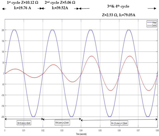
Figure 8.
Output voltage and current waveforms for RL load.
The harmonic content present in the output voltage and current waveforms fed with impedance load obtained from FFT analysis are 1.25% and 1.01%, it is shown in Figure 9a,b. Current THD is reduced due to inductance load added in the circuit which smoothen the current waveform and small phase swift occurs due to inductance.
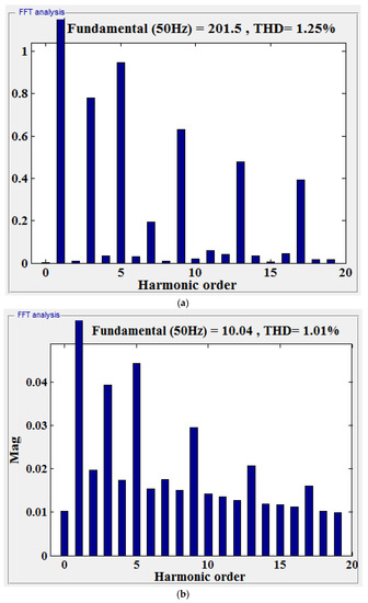
Figure 9.
(a) FFT for output voltage fed with RL load; (b) FFT for output current fed with RL load.
When motor is supplied by a cascaded two stages of SLMLI of 81 levels in the output, the speed of the motor is shown in Figure 10 for the load torque of 1 Nm, due to load torque it settles at average speed of 1730 rpm.
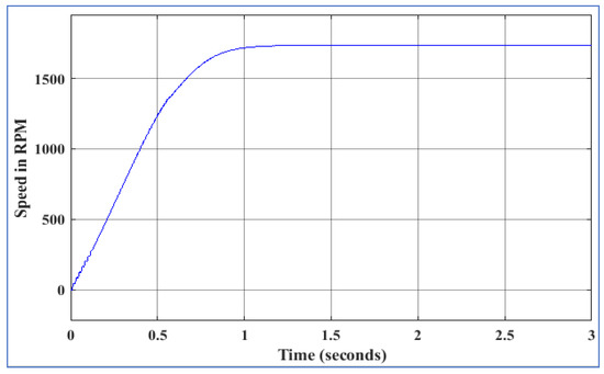
Figure 10.
Speed of single stage SLMLI fed induction motor.
The electromagnetic torque produced by the given induction motor fed by the cascaded two stages of SLMLI is shown in Figure 11.
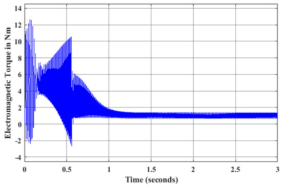
Figure 11.
Electromagnetic torque of single stage SLMLI fed induction motor.
FFT analysis for the source voltage and current of induction motor is shown in Figure 12a which contains the fundamental frequency of 60 Hz and the peak magnitude is 156.7 V and the voltage THD is 1.24%. The input current drawn from the SLMLI fundamental peak is 3.434 A and the THD is 4.12% as shown in Figure 12b.
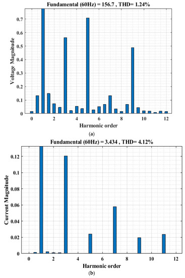
Figure 12.
(a) FFT analysis for input voltage for induction motor load; (b) FFT analysis for current for induction motor load.
5.1. Speed Control Technique
In this speed control has been done by varying the supply voltage given to the induction motor. Specification of the inverter is shown in Table 6, as per proposed system the output voltage has 81-levels which gives to the rated voltage of 110 V (rms) due to that it will produce the rated speed of the induction motor which is 1800 RPM. The magnitude of the direct current voltage sources in switched ladder multilevel inverter stage-1 are selected as V1 = 4V and V2 = 12 V. For the stage-2 switched ladder multilevel inverter the amplitude of the voltage sources is selected as V3 = 16 V and V4 = 48 V, the specification of inverter and induction motor is given in Table 6.
Table 6.
Specification of Inverter and Induction motor.
Figure 13 shows the various speed responses of the induction motor with respect to different input voltages. The blue colored line in the graph shows the speed response for the rated voltage given by the inverter which is nearly rotates at rated speed of 1736 RPM.
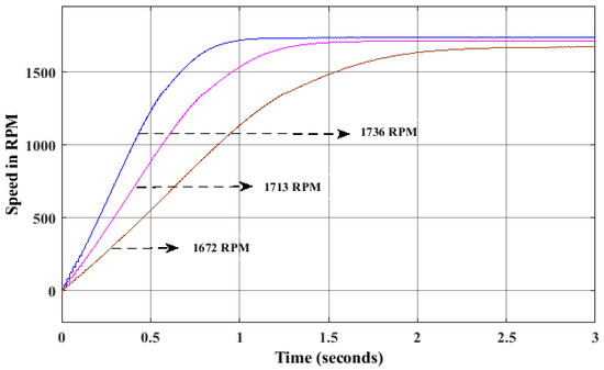
Figure 13.
Various speed responses of the induction motor with respect to different input voltages.
Variation in the inverter output voltage can be achieved by changing the magnitude of sinusoidal reference control logic and it is shown in Figure 14. In order to vary the speed of the motor, change in magnitude of reference is done; the other two different speeds are shown in Figure 13 that is plotted with pink and brown lines. These speeds are less compared to the rated speed, less than rated speeds only achieved by this control technique.
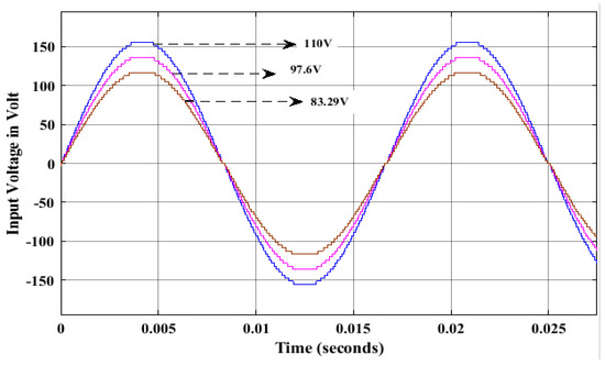
Figure 14.
Different Output voltages of a SLMLI.
Figure 14 shows the inverter output voltages for different magnitudes, blue colored voltage in Figure has the magnitude of 110 V rms which gives to the induction motor as per motor rating. The other two colored voltages in the Figure 14 are reduced voltage and the magnitude is less compared to the rated voltage of the motor.
The load torque is applied as 1 Nm at 3 s and 1.25 Nm at 6 s. The variation in load torque, speed and current waveform are shown in Figure 15, Figure 16 and Figure 17.
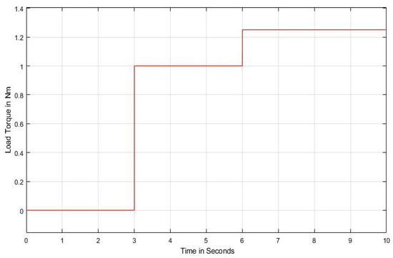
Figure 15.
Load torque vs. time.
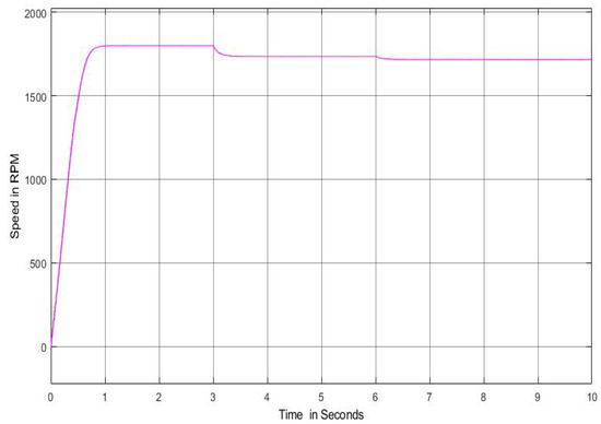
Figure 16.
Speed variations for various load torque.
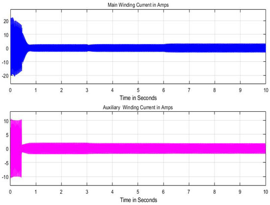
Figure 17.
Current variations for various load torque.
The main winding current is zoomed and it is shown in Figure 18.
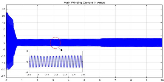
Figure 18.
Main winding current for various load torque.
The proposed SLMLI is constructed with low number of power electronics devices for generating 81 levels in the output voltage. Design of DC sources is framed with two different algorithms. Furthermore, the SLMLI structure is tested with single phase induction motor and Speed control has been performed with satisfactory results.
5.2. Cost-Benefit Analysis of 81-Level SLMLI with Conventional MLI’s
The unit price of the component is given in Table 7. The cost-benefit analysis of proposed 81-level switched ladder in comparison with the conventional MLI is shown in Table 8. From the cost analysis it can be concluded that the proposed inverter can be designed with low cost compared to conventional MLI’s.
Table 7.
Unit price of the circuit components.
Table 8.
Cost-benefit analysis of 81-level SLMLI with conventional MLI’s.
6. Conclusions
Much research had been undertaken to design multilevel inverters with reduced circuit components, minimum losses, low cost, and compact size with high efficiency. A survey is made in this paper to identify the type of multilevel inverter used in high and medium power applications such as Electric Vehicle, Power drives, Grid integration systems, etc. A detailed review is conducted on the recent multilevel inverter design with reduced switch count to find out the challenges and key issues. Significant issues of various multilevel inverter designs are provided in terms of number of diodes, switches, source utilization and filter requirement. A new 81-level switched ladder inverter is configured using MATLAB/Simulink and tested with change in resistive and impedance load at equal period of time. The results were analyzed in terms of harmonic content. Further, the output of 81-level inverter is connected to 0.25 HP, 110 V single phase induction motor. The speed of the induction motor is observed for change in input voltages and the various speed curves were presented. Variation in the speed with respect to change in load torque is plotted in this paper, thus the performance of the single phase induction motor fed by 81-level switched ladder inverter is found satisfactory.
Author Contributions
Conceptualization, methodology and writing—review, V.L., D.R. and B.M.; project administration, funding acquisition editing and supervision, G.K.S. and M.R. All authors have read and agreed to the published version of the manuscript.
Funding
The authors thank the Department of Electrical and Electronics Engineering, Anna University, India for the financial support through RUSA 2.0 (PO 2) project and FONDECYT Regular 1191028 and FNDAP SERC Chile 15110019.
Conflicts of Interest
The authors declare no conflict of interest.
Abbreviations
| MLI | Multilevel Inverter |
| DC | Direct Current |
| THD | Total Harmonics Distortion |
| PWM | Pulse Width Modulation |
| CHB | Cascaded Half Bridge |
| MLIRS | Multilevel Inverter with Reduced Switch |
| DVR | Dynamic Voltage Restorer |
| SLMLI | Switched Ladder Multilevel Inverter |
| FFT | Fast Fourier Transform |
| Nm | Newton meter |
| RPM | Revolution Per Minute |
| RMS | Root Mean Square |
References
- Roemer, F.; Ahmad, M.; Chang, F.; Lienkamp, M. Optimization of a cascaded h-bridge inverter for electric vehicle applications including cost consideration. Energies 2019, 12, 4272. [Google Scholar] [CrossRef]
- Karthikeyan, D.; Vijayakumar, K.; Jagabar Sathik, M. Generalized cascaded symmetric and level doubling multilevel converter topology with reduced THD for photovoltaic applications. Electronics 2019, 8, 161. [Google Scholar]
- Samadaei, E.; Salehi, A.; Iranian, M.; Pouresmaeil, E. Single DC source multilevel inverter with changeable gains and levels for low-power loads. Electronics 2020, 9, 937. [Google Scholar] [CrossRef]
- Sunddararaj, S.P.; Srinivasarangan Rangarajan, S.; Subashini, N. An extensive review of multilevel inverters based on their multifaceted structural configuration, triggering methods and applications. Electronics 2020, 9, 433. [Google Scholar] [CrossRef]
- Vijayaraja, L.; Kumar, S.G.; Rivera, M. A review on multilevel inverter with reduced switch count. In Proceedings of the 2016 IEEE International Conference on Automatica (ICA-ACCA), Curico, Chile, 19–21 October 2016; pp. 1–5. [Google Scholar]
- Ahmad, A.; Anas, M.; Sarwar, A.; Zaid, M.; Tariq, M.; Ahmad, J.; Beig, A.R. Realization of a generalized switched-capacitor multilevel inverter topology with less switch requirement. Energies 2020, 13, 1556. [Google Scholar] [CrossRef]
- Ganesh, B.; Murugan, N.; Nallaswamy, M.; Rajkumar, K.; Vijayaraja, L.; Ganesh Kumar, S.; Rivera, M. Implementation of twenty seven level and fifty one level inverter using constant voltage sources. In Proceedings of the 2019 IEEE CHILEAN Conference on Electrical, Electronics Engineering, Information and Communication Technologies (CHILECON), Valparaiso, Chile, 13–27 November 2019; pp. 1–4. [Google Scholar]
- Vijayaraja, L.; Kumar, S.G.; Rivera, M. A new topology of multilevel inverter with reduced part count. In Proceedings of the 2018 IEEE International Conference on Automation/XXIII Congress of the Chilean Association of Automatic Control (ICA-ACCA), Concepcion, Chile, 17–19 October 2018; pp. 1–5. [Google Scholar]
- Aganah, K.A.; Luciano, C.; Ndoye, M.; Murphy, G. New switched-dual-source multilevel inverter for symmetrical and asymmetrical operation. Energies 2018, 11, 984. [Google Scholar] [CrossRef]
- Vijayaraja, L.; Dhanasekar, R.; Balaji, M.; Ganesh Kumar, S. Performance study of 81-level inverter using two stage switch ladder circuit. In Proceedings of the 1st International Science Exhibition Congress Symposium (SECS-2020), Jharkhand, India, 12–13 September 2020. [Google Scholar]
- Ponkumar, S.; Rivera, M.; Kamroon, F.; Kumar, S.G. Realization of cascaded multilevel inverter. In Proceedings of the 2017 CHILEAN Conference on Electrical, Electronics Engineering, Information and Communication Technologies (CHILECON), Pucon, Chile, 18–20 October 2017; pp. 1–7. [Google Scholar]
- Hassan, A.; Yang, X.; Chen, W.; Houran, M.A. A state of the art of the multilevel inverters with reduced count components. Electronics 2020, 9, 1924. [Google Scholar] [CrossRef]
- Thiyagarajan, V. Simulation analysis of 51-level inverter topology with reduced switch count. Mater. Today Proc. 2020, 33, 3870–3876. [Google Scholar] [CrossRef]
- Ali, A.I.M.; Sayed, M.A.; Takeshita, T. Isolated single-phase single-stage DC-AC cascaded transformer-based multilevel inverter for stand-alone and grid-tied applications. Int. J. Electr. Power Energy Syst. 2021, 125, 106534. [Google Scholar] [CrossRef]
- Nirmal Mukundan, C.M.; Jayaprakash, P.; Subramaniam, U.; Almakhles, D.J. Trinary hybrid cascaded h-bridge multilevel inverter-based grid-connected solar power transfer system supporting critical load. IEEE Syst. J. 2020. [Google Scholar] [CrossRef]
- Rangarajan, P. Investigation of modified multilevel inverter topology for PV system. Microprocess. Microsyst. 2019, 71, 102870. [Google Scholar]
- Zaid, M.M.; Ro, J.-S. Optimal design of a cascaded rectangular-type and circle-type multilevel inverters with a new switching technique. IET Power Electron. 2020, 13, 2831–2846. [Google Scholar] [CrossRef]
- Kim, S.-M.; Lee, E.-J.; Lee, J.-S.; Lee, K.-B. An improved phase-shifted DPWM method for reducing switching loss and thermal balancing in cascaded h-bridge multilevel inverter. IEEE Access 2020, 8, 187072–187083. [Google Scholar] [CrossRef]
- Sahoo, S.; Ahmed, I. Common mode voltage reduction in NPC multilevel inverter by SVPWM using gh-coordinate system. In Proceedings of the International Conference on Computational Intelligence for Smart Power System and Sustainable Energy (CISPSSE), Keonjhar, Odisha, India, 29–31 July 2020; pp. 1–6. [Google Scholar]
- Sen, P. Novel multilevel inverter based standalone PV System using reduced number of components. In Proceedings of the International Conference on Renewable Energy Integration into Smart Grids: A Multidisciplinary Approach to Technology Modelling and Simulation (ICREISG), Bhubaneswar, India, 14–15 February 2020; pp. 111–115. [Google Scholar]
- Siddique, M.D.; Mekhilef, S.; Shah, N.M.; Sarwar, A.; Iqbal, A.; Memon, M.A. A new multilevel inverter topology with reduce switch count. IEEE Access 2019, 7, 58584–58594. [Google Scholar] [CrossRef]
- Joshi, N.R.; Sant, A.V. Analysis of a new symmetric multilevel inverter topology with reduced component count. In Proceedings of the International Conference on Emerging Trends in Information Technology and Engineering (ic-ETITE), Vellore, India, 24–25 February 2020; pp. 1–6. [Google Scholar]
- Ranjbarizad, V.; Aalami, M.; Babaei, E. A new topology for cascaded multilevel inverter to generate more voltage levels with a reduced count of power switches. In Proceedings of the 4th International Conference on Power Electronics and their Applications (ICPEA), Elazig, Turkey, 25–27 September 2019; pp. 1–7. [Google Scholar]
- Kshirsagar, A.; Kaarthik, R.S.; Rahul, A.; Gopakumar, K.; Umanand, L.; Biswas, S.K.; Cecati, C. 17-level inverter with low component count for open-end induction motor drives. IET Power Electron. 2018, 11, 922–929. [Google Scholar] [CrossRef]
- Dhanamjayulu, C.; Khasim, S.R.; Padmanaban, S.; Arunkumar, G.; Holm-Nielsen, J.B.; Blaabjerg, F. Design and implementation of multilevel inverters for fuel cell energy conversion system. IEEE Access 2020, 8, 183690–183707. [Google Scholar] [CrossRef]
- Kahwa, A.; Obara, H.; Fujimoto, Y. Estimation and analysis of power loss in a reduced switches count H-bridge multilevel inverter. In Proceedings of the IEEE International Conference on Mechatronics (ICM), Ilmenau, Germany, 18–20 March 2019; pp. 25–30. [Google Scholar]
- Rajkumar, K.; Parthiban, P. Performance investigation of transformerless DVR based on T-type multilevel inverter with reduced switch count. In Proceedings of the IEEE International Conference on Sustainable Energy Technologies and Systems (ICSETS), Bhubaneswar, India, 26 February–1 March 2019; pp. 236–241. [Google Scholar]
- Abdoli, H.; Khorsandi, A.; Eskandari, B.; Moghani, J.S. A new reduced switch multilevel inverter for PV applications. In Proceedings of the 11th Power Electronics, Drive Systems, and Technologies Conference (PEDSTC), Tehran, Iran, 4–6 February 2020; pp. 1–5. [Google Scholar]
- Nasiri Avanaki, H.; Barzegarkhoo, R.; Zamiri, E.; Yang, Y.; Blaabjerg, F. Reduced switch-count structure for symmetric multilevel inverters with a novel switched-DC-source submodule. IET Power Electron. 2019, 12, 311–321. [Google Scholar] [CrossRef]
- Babaei, E.; Kangarlu, M.F.; Hosseinzadeh, M.A. Asymmetrical multilevel converter topology with reduced number of components. IET Power Electron. 2013, 6, 1188–1196. [Google Scholar] [CrossRef]
- Lee, S.S. Single-stage switched-capacitor module (S3CM) topology for cascaded multilevel inverter. IEEE Trans. Power Electron. 2018, 33, 8204–8207. [Google Scholar] [CrossRef]
- Majumdar, S.; Mahato, B.; Jana, K.C. Analysis of most optimal multi-unit multi-level inverter having minimum components and lower standing voltage. IETE Tech. Rev. 2020, 1–17. [Google Scholar] [CrossRef]
- Ray, S.; Gupta, N.; Gupta, R.A. A comprehensive review on cascaded h-bridge inverter-based large-scale grid-connected photovoltaic. IETE Tech. Rev. 2017, 34, 463–477. [Google Scholar] [CrossRef]
- Alishah, R.S.; Hosseini, S.H.; Babaei, E.; Sabahi, M. Optimal design of new cascaded switch-ladder. Multilevel inverter structure. IEEE Trans. Ind. Electron. 2017, 64, 2072–2080. [Google Scholar] [CrossRef]
- Umashankar, S.; Sreedevi, T.S.; Nithya, V.G.; Vijayakumar, D. A new 7-level symmetric multilevel inverter with minimum number of switches. Int. Sch. Res. Not. 2013. [Google Scholar] [CrossRef]
- Prakash, S.; Kumar, L.; Gupta, S.; Agrawal, N. Implementation of symmetrical multilevel inverter topology. In Proceedings of the IEEE 1st International Conference on Power Electronics, Intelligent Control and Energy Systems (ICPEICES), Delhi, India, 4–6 July 2016; pp. 1–6. [Google Scholar]
- Bharath, K.; Satputaley, R.J. Single phase asymmetrical cascaded multilevel inverter design for induction motor. IJEEDC 2013, 1, 8–13. [Google Scholar]
- Seth, N.; Goel, V.; Kulkarni, R.D.; Joshi, V.P. Performance analysis of seven level three phase asymmetric multilevel inverter at various modulation indices. In Proceedings of the 2016 International Conference on Electrical Power and Energy Systems (ICEPES), Bhopal, India, 14–16 December 2016; pp. 407–413. [Google Scholar]
- Pires, V.F.; Silva, J.F. Hybrid cascade multilevel inverter using a single DC source for open-end winding induction motors. In Proceedings of the 2012 IEEE International Conference on Industrial Technology, Athens, Greece, 19–21 March 2012; pp. 966–970. [Google Scholar]
- Khosroshahi, M.T. Crisscross cascade multilevel inverter with reduction in number of components. IET Power Electron. 2014, 7, 2914–2924. [Google Scholar] [CrossRef]
- Oskuee, M.R.J.; Salary, E.; Najafi-Ravadanegh, S. Creative design of symmetric multilevel converter to enhance the circuit’s performance. IET Power Electron. 2015, 8, 96–102. [Google Scholar] [CrossRef]
- Wang, L.; Wu, Q.H.; Tang, W. Novel cascaded switched-diode multilevel inverter for renewable energy integration. IEEE Trans. Energy Convers. 2017, 32, 1574–1582. [Google Scholar] [CrossRef]
- Alishah, R.S.; Nazarpour, D.; Hosseini, S.H.; Sabahi, M. Novel topologies for symmetric, asymmetric, and cascade switched-diode multilevel converter with minimum number of power electronic components. IEEE Trans. Ind. Electron. 2014, 61, 5300–5310. [Google Scholar] [CrossRef]
- Su, G.-J. Multilevel DC-link inverter. IEEE Trans. Ind. Appl. 2005, 41, 848–854. [Google Scholar] [CrossRef]
- Liu, J.; Cheng, K.W.E.; Ye, Y. A cascaded multilevel inverter based on switched-capacitor for high-frequency AC power distribution system. IEEE Trans. Power Electron. 2014, 29, 4219–4230. [Google Scholar] [CrossRef]
- Gupta, K.K.; Jain, S. A novel multilevel inverter based on switched DC sources. IEEE Trans. Ind. Electron. 2014, 61, 3269–3278. [Google Scholar] [CrossRef]
- Mokhberdoran, A.; Ajami, A. Symmetric and asymmetric design and implementation of new cascaded multilevel inverter topology. IEEE Trans. Power. Electron. 2014, 29, 6712–6724. [Google Scholar] [CrossRef]
- Arun, N.; Noel, M.M. Crisscross switched multilevel inverter using cascaded semi-half-bridge cells. IET Power Electron. 2018, 11, 23–32. [Google Scholar] [CrossRef]
- Ajami, A.; Oskuee, M.R.J.; Mokhberdoran, A.; van den Bossche, A. Developed cascaded multilevel inverter topology to minimise the number of circuit devices and voltage stresses of switches. IET Power Electron. 2014, 7, 459–466. [Google Scholar] [CrossRef]
- Thiyagarajan, V.; Somasundaram, P. Multilevel inverter topology with modified pulse width modulation and reduced switch coun. Acta Polytechnica Hungarica 2018, 15, 141–167. [Google Scholar]
- Chappa, A.; Gupta, S.; Sahu, L.K.; Gautam, S.P.; Gupta, K.K. Symmetrical and asymmetrical reduced device multilevel inverter topology. IEEE J. Emerg. Sel. Top. Power Electron. 2019, 9, 885–896. [Google Scholar] [CrossRef]
- Ajami, A.; Mokhberdoran, A.; Oskuee, M.R.J. A new topology of multilevel voltage source inverter to minimize the number of circuit devices and maximize the number of output voltage levels. J. Electr Eng Technol. 2013, 8, 1328–1336. [Google Scholar] [CrossRef]
- Siddique, M.D.; Mekhilef, S.; Shah, N.M.; Memon, M.A. Optimal design of a new cascaded multilevel inverter topology with reduced switch count. IEEE Access 2019, 7, 24498–24510. [Google Scholar] [CrossRef]
- Samadaei, S.E.; Kaviani, M.; Bertilsson, K. A 13-levels module (K-type) with two DC sources for multilevel inverters. IEEE Trans. Ind. Electron. 2019, 66, 5186–5196. [Google Scholar] [CrossRef]
- Thiyagarajan, V.; Somasundaram, P.; Ramash Kumar, K. Simulation and analysis of novel extendable multilevel inverter topology. J. Circuits Syst. Comput. 2020, 28, 1950089. [Google Scholar] [CrossRef]
- Zeng, J.; Lin, W.; Cen, D.; Liu, J. Novel K-type multilevel inverter with reduced components and self-balance. IEEE J. Emerg. Sel. Top. Power Electron. 2020, 8, 4343–4354. [Google Scholar] [CrossRef]
- Loganathan, V.; Srinivasan, G.K.; Rivera, M. Realization of 485 Level Inverter Using Tri-State Architecture for Renewable Energy Systems. Energies 2020, 13, 6627. [Google Scholar] [CrossRef]


Publisher’s Note: MDPI stays neutral with regard to jurisdictional claims in published maps and institutional affiliations. |
© 2021 by the authors. Licensee MDPI, Basel, Switzerland. This article is an open access article distributed under the terms and conditions of the Creative Commons Attribution (CC BY) license (http://creativecommons.org/licenses/by/4.0/).