Abstract
A simple, nearfield transformation meta-structure is proposed to increase the directivity of resonant cavity antennas (RCA). The meta-structure is comprised of 14 × 14 meta-atoms or so called “unit-cells”, adding localized phase delays in the aperture of the RCA and thus increasing its broadside directivity. A prototype of the meta-structure is additively manufactured using the stereolithograpy process and has a profile of 0.56. With the meta-structure integrated with the RCA, it demonstrates a measured broadside directivity of 20.15 dBi without affecting its half-power directivity bandwidth. Benefiting from additive manufacturing, the proposed approach is a simple, light-weight, low-cost, and planar approach that can be tailored to achieve medium-to-high gains with RCAs.
1. Introduction
Advancements in additive manufacturing (AM) have led to diverse applications in manufacturing and prototyping technologies, with increased accuracy and reduced costs. This is no different for wireless and antenna technologies, where AM unlocks the potential for realizing low-cost and lightweight Radio Frequency (RF) components such as lens antennas, metasurfaces, and waveguide components [1,2,3]. Common methods of AM include fused deposition modelling (FDM) and stereolithographic apparatus (SLA) [2,4]. In recent years, interesting applications of AM have been envisioned to realize directive antennas such as lens antennas [4,5,6] and meta-surface-based antennas [7,8,9]. Three-dimensional (3D)-printed lens antennas were demonstrated, where the lenses were mounted at focal distances from the feeding source or at the interface achieving directivity in the range of 15–20 dBi. The additively manufactured RF components present a notable improvement in precision with largely reduced materials and manufacturing costs compared to their subtractively produced, also known as “machined”, counterparts [10,11]. These include Luneburg lens and Eaton lens antennas fabricated using the poly-jetting method with a peak directivity of 20.3 dBi and 13.3 dBi in X-band, respectively [4,12]. These lenses were three-dimensional volumetric structures and had profiles extending over 3–4 wavelengths. Two-dimensional 3D-printed transmit-arrays have also been proposed previously, but they require source antennas to be placed at a few wavelengths, thus having higher profiles and larger footprints [13,14]. Flat lenses such as gradient index with variable plastic density [6] and Fresnel zone-plate antennas using dielectric polycarbonate infill variation were also demonstrated in [15,16]. The profile of the lens structure was reduced compared to their 3D counterparts; nonetheless, the illumination of these lenses requires the feeding source (horns or waveguide apertures) to be at focal length, and thus, the overall profile is still relatively high. Moreover, the Transformation Optics (TO) concept was used for the design of dielectric 3D printing lens antenna [17,18], where the electromagnetic waves were directed in particular direction. Additionally, to steer the beam, additive manufacturing techniques were applied [19,20]. Similarly, asymmetric cylindrical-post metasurfaces [21] and comb mushroom-like meta-structures [22] were proposed using the FDM process for increasing directivity in the broadside and end fire directions, yet reducing the overall profile has always been an interesting challenge.
In this article, we propose a low-profile, nearfield transformation meta-structure to improve the directivity of RCAs. RCAs have emerged as a viable alternative to obtain increased directivity with compact, simple, and planar configuration [23]. However, the directivity of the RCAs is often reduced by nonuniform field distribution over its aperture [24,25]. Additionally, broadside directivity and gain of RCAs is improved through the use of superstrates with transverse permittivity gradient [26], but this required diverse permittivity values materials with different thickness, which creates difficulties in obtaining matched permittivity material and increases the cost. The proposed meta-structure is realized using the Stereolithography Apparatus (SLA) process and comprises of a 14 × 14 grid of meta-atoms or-so called “unit-cells”, which makes the aperture-field distribution uniform. Each meta-atom is capable of inducing a localized phase transformation in the range of 0 to 74. The prototype of the meta-structure realized with SLA process is integrated with an RCA, and a measured broadside directivity of 20.15 dBi is demonstrated. Thus, the meta-structure doubles the directivity of the RCA without reducing its half-power directivity bandwidth. The profile of the proposed meta-structure is only 0.56, and the overall profile of the RCA prototype is 1.4. The novelty of the proposed antenna prototype lies in reducing the overall profile of the antenna, being light in weight, having reduced, cost and improving directivity without decreasing the half power directivity bandwidth. The rest of the manuscript is organized as follows. Section 2 describes the configuration of the RCA and the strategy for designing the nearfield transformation meta-structure. Section 3 presents the details of prototype fabrication, measured results, and associated discussions, and Section 4 concludes the article.
2. Configuration of RCA and the Nearfield Transformation Meta-Structure
The schematic of the RCA and the concept of the nearfield transformation meta-structure are shown in Figure 1. As shown in Figure 1, the RCA consists of a ground plane with a feed source in the center and a thin layer of dielectric with relative permittivity, = 9.8, and tan of 0.002 with thickness, t = 2.54 mm, and spaced as distance, h = 0.5 (where = 25 mm at f = 12 GHz). The lateral size of the RCA is 4 × 4. It has been identified that, when this RCA is excited, the electric field distribution in Reference Plane 1 (RP1) does not have a uniform transmission phase [24,25,27]. Thus, the directivity of this antenna is notably reduced.
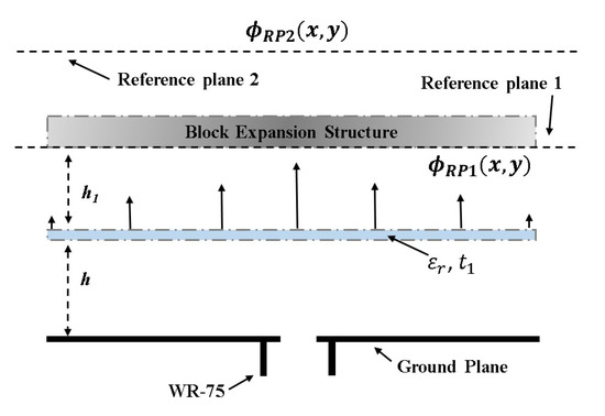
Figure 1.
Conceptual model of the proposed resonant cavity antenna (RCA) with the block expansion meta-structure (BES).
With the meta-structure installed in place of RP1 (see Figure 2a), it introduces localized phase delays to transform the field distribution in RP1, making it uniform in Reference Plane 2 (RP2), thus improving the directivity of the RCA. Considering the block-like construction of the meta-atoms, the meta-structure is referred to as the block expansion structure (BES) in the rest of the article. Figure 2b,c shows the phase values in (x,y) before and after correction, respectively. The phase value is noted at a distance of 3.75 mm from the center of an aperture to 48.75 mm at the interval of 7.5 mm. The negative sign of these values as shown on the opposite side depicts the respective distances from the center of the aperture. For instance, along the right side of the center of the aperture in 3.75 mm and below it at the same distance, we noted the phase values 117.4, 34.92, and 35.91 without BES and with BES before and after phase correction, respectively. This phase distribution shows how the meta-structure is designed. Since the cube dimension is controllable with only one parameter, we chose the cube as a unit cell that is held by three perpendicular cylindrical rods. Commercially available clear resin material ( = 2.76 and tan of 0.059) was selected for prototyping using the Stereolithography Apparatus (SLA). A clear resin material was selected due to its excellent dimensional tolerance, surface smoothness, and superior precision of fine features compared to the commonly used Acrylonitrile Butadiene Styrene (ABS) material. While the electrical properties of clear resin and ABS material are similar, the former allows a feature resolution as fine as 0.05 mm. The response of the meta-structure depends on the base antenna, where we performed the numerical simulations to study its response with a broadband source and found that response versus frequency is stable. However, with dual-layer RCA used as the base antenna, the stable response is not immediately demonstrated. A meta-atom resembles a hypothetical cube, with a scalable three-dimensional cube centered on an equal-length three-axis rod-like structure. The lengths of these rods in a single unit-cell are equal in the x, y, and z directions, i.e., 7.5 mm, which is the size of a unit-cell. The cube in each of the unit-cells concentrically expands to take on various sizes. The cube size can be as small as 0.5 mm (0.02) and as large as the hypothetical unit-cell itself, i.e., 7.5 mm (0.3). We studied the transmission phase delays of these unit-cells in CST Microwave Studio, using periodic boundary conditions and found that a single unit-cell can provide normalized a phase transformation in the range from 0 to 74 and transmission magnitude greater than 0.9. We sampled RP1 as a two-dimensional (2D) grid with a sampling size of 0.3 and computed the phase, which showed a maximum difference of nearly 120. Since a single meta-atom of the BES can only provide a maximum phase transformation of 74, two meta-atoms were stacked to achieve a phase transformation over 120.
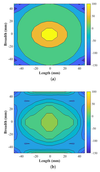
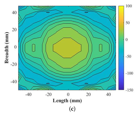
Figure 2.
(a) Phase values above RCA in (x,y) (b), phase values in (x,y) before correction, and (c) modulated phase values in (x,y) after correction.
Figure 3 shows the computed transmission magnitude and phase of two stacked meta-atoms, as the cube size varied from 0.5 to 7.5 mm. For each case of (x,y), where x,y is 1 to 14, the scale of a cube in meta-atoms was selected based on the data in Figure 3 and a dual-layer BES was constructed. This BES, when placed in place of RP1, leads to a significantly uniform phase distribution in RP2.
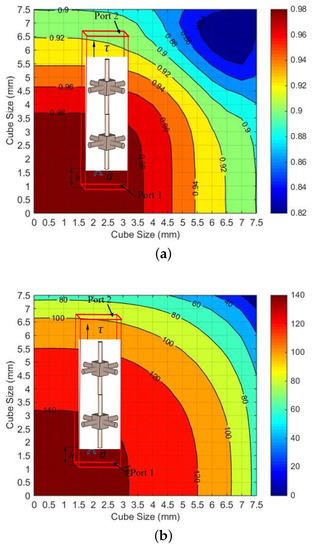
Figure 3.
Estimate of (a) the transmission magnitude and (b) normalized transmission phase achievable using a dual-layer block expansion meta-structure (BES).
The Figure 4a shows a 2D map of the electric field phase in RP1, whereas further improvement in the phase is noted after the placement of BES, as depicted in Figure 4b. Moreover, correction in the phase distribution is performed by fine-tuning the cube sizes, which further generated the uniform phase distribution as observed in Figure 4c. Note that, once the BES was constructed using the unit-cell data, we fine-tuned some of the unit-cell dimensions in the interval of 0.5 mm so as to have an improvement in the phase uniformity using full-wave parametric simulations, leading to the final meta-structure termed “corrected-BES”. The parametric analysis of the block expansion structure was performed with the step size increment of 0.5 mm in the cube dimension for which the values increased from a minimum of 0.5 mm to a maximum of 7.5 mm in the overall dimension across the two layer of cubes. We maintained the database of two layers of cubes considering the transmission coefficient magnitude and phase values, as discussed earlier. From these generated values, the tabular form of the magnitude and phase were maintained and corresponded to cube sizes in two layers. The normalized phase values were incremented at an interval of 5 from nominal value of 0 to maximum of 145, which correspond to transmission values between 0.8 to 0.9. The parametric analysis was performed for the respective aperture positions of 3.75 mm, 11.25 mm, 18.75 mm, 26.25 mm, 33.75 mm, 41.25 mm, and 48.75 mm considering the phase values, and we have tried to decrease the overall phase variation across the aperture. The successive change in cubes size at the defined aperture distance resulted in a more uniform phase distribution. For instance, at the distance of 26.25 mm from the center of the aperture, the nearest required phase increased by 20 from 95 to 115 and the transmission magnitude increased from 0.89 to 0.93. This resulted in the decreased phase variation from 17 to 6. This improved the directivity by nearly 3 dB and reduced the side lobe level by nearly 2.5 dB. Thus, the BES provides the possibility not only to make the aperture field distribution uniform but also to apply a required nearfield distribution profile for tailoring radiation pattern masks where required [28,29]. The generated 3D-printed BES with two building blocks in the axial direction is shown in Figure 5. The top, bottom, and side views are respectively shown in Figure 5a–c. As noticed around the center of the aperture, the cube dimension is relatively higher and, as we move towards the edge, the cube dimensions become smaller, which is due to the requirement of the desire cube sizes from the database in order to acquire a more uniform phase distribution above the proposed BES. This eventually improves the radiation characteristics of a base antenna, as discussed in the next section.
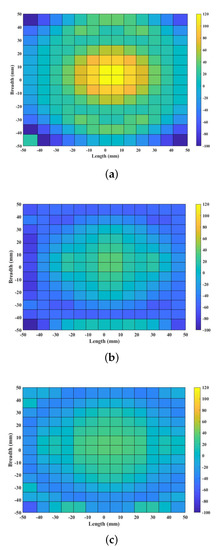
Figure 4.
(a) Aperture phase distribution noted in Reference Plane 1, (b) improvement in aperture phase observed in 2D phase distribution over the aperture recorded in Reference Plane 2 before correction in BES, and (c) phase distribution over the aperture recorded in Reference Plane 2 after correction in BES.
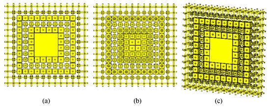
Figure 5.
Two-layer lattice block expansion structure: (a) top view, (b) bottom view, and (c) side view.
3. Fabrication, Measurements, and Discussions
A prototype of the dual-layer BES with its detail dimensions, as shown in Figure 6a, was manufactured and integrated with the RCA to validate the proposed concept. BES has equal lengths and breadths of 100 mm, as indicated by “L”, and thicknesses of 15 mm, as denoted by “H”.
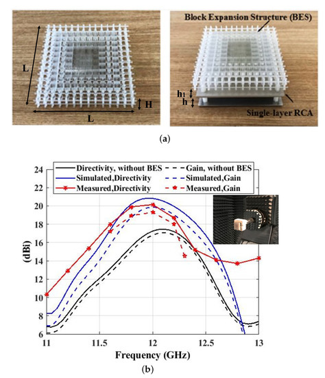
Figure 6.
(a) Fabricated prototype of the dual-layer BES manufactured using stereolithographic process (left) and the RCA with the BES installed (right). (b) Simulated and measured broadside directivity and gain of the RCA with and without BES attached. The inset shows the RCA under test at AusAMF.
The RCA prototype, shown in the inset of Figure 6b, was made of three layers, i.e., an aluminum ground plane, a layer of dielectric sheet (Rogers Thermoset Microwave Material (TMM) 10i; = 9.8, and tan of 0.002; and thickness, t = 2.54 mm) placed at a height h = 12.5 mm above the ground plane, and the BES placed at a height h1 = 6.25 mm placed above the dielectric layer. The RCA is excited by a rectangular slot cut in the center of the ground plane, and has dimensions of 12.5 mm × 6.25 mm. The slot is fed by a standard WR-75 waveguide-to-coax transition adapter. Four spacer screws made out of Teflon were installed to assemble the layers (see Figure 6a), each placed on the corners of the RCA. Radiation characteristics of the prototype were tested using the NSI 700S-50 Spherical Nearfield to Farfield system at the Australian Antenna Measurement Facility (AusAMF). A maximum directivity of 20.15 dBi and a peak realized gain of 19.3 dBi was measured at 12 GHz in the broadside direction. The gain comparison method, which has an inherent tolerance of ±0.5 dBi, was used for gain measurements, with the NSI-SGH75 antenna used as a reference. The half-power directivity and gain bandwidth extended from 11.65 GHz to 12.43 GHz. To put this in context, numerically computed as well as measured values of broadside directivity and gain are shown in Figure 6b. The half-power bandwidths as well as the peak gain and directivity compare very well with the measured results. Moreover, it can be noted that the BES increased the gain of the RCA without reducing its half-power bandwidth, which is unlike the behavior of a conventional RCA, where increasing layers of the Partially Reflective Surface (PRS) increase the gain but reduce the bandwidth.
Figure 7a,b show the radiation patterns measured in both principal planes at 12 GHz. It is shown that the RCA radiates a pencil beam directed towards broadside, with a very low cross-polarization level. The side lobe level (SLL) in E-plane and H-plane were noted as −16.5 dB and −19 dB, respectively. Cross polarization levels were fairly low, reaching −20 dB and −25 dB in the respective principal planes. Voltage standing wave ratio (VSWR) was measured using a KeysightPNA-X N5242A Vector Network Analyzer as shown in Figure 8. The matched bandwidth of the RCA (VSWR < 2) started from 11.4 GHz and continued beyond 13 GHz. However, the usable bandwidth of the RCA is where the matched bandwidth overlaps with the half-power directivity bandwidth (11.65–12.43 GHz), which is well-matched including at f = 12 GHz.
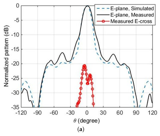
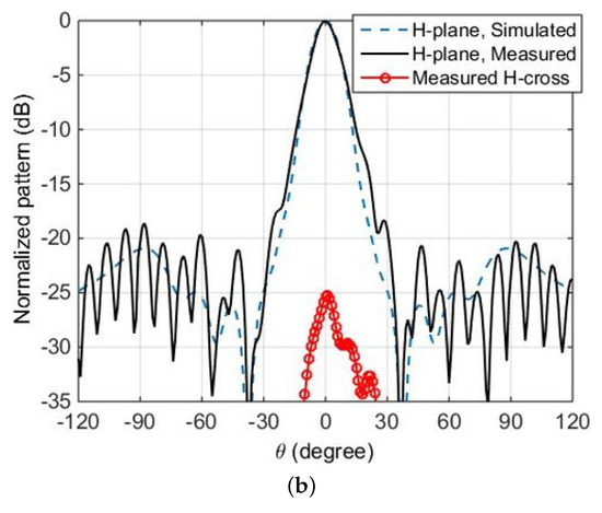
Figure 7.
Normalized radiation patterns of the RCA at fc = 12 GHz in (a) E-plane and (b) H-plane.
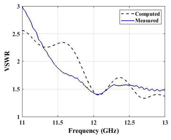
Figure 8.
Computed and measured Voltage Standing Wave Ratio (VSWR) of the RCA with the BES.
Table 1 compares the performance of the proposed meta-structure with previous works. As noticed from Table 1, the overall height from the source is comparatively less compared with other proposed antenna prototypes. The overall height from the source corresponds to the height of the antenna prototype from the ground plane; in this case, the overall height is 36.29 mm (1.45), which is obtained by adding the individual heights considering first the placement of PRS at 12.5 mm (0.5) distance from the ground plane, then by adding a thickness of 2.54 mm, and finally by adding the quarter wavelength distance from the PRS surface. Additionally, the height of the structure signifies the thickness of the proposed BES, where it is 15 mm (0.6), which is significantly less as observed against the other proposed prototypes. It can be seen that the proposed meta-structure is light weight and compact in size and has a lower profile with less side lobe level, while also yielding a comparable aperture efficiency of 47%. This represents an improvement of 56% in the aperture efficiency of the RCA, where the meta-structure increased the overall profile of the RCA by 70%.

Table 1.
Comparing the performance of the proposed meta-structure with relevant works in the literature.
4. Conclusions
We demonstrated a simple, light-weight, low-cost, and planar approach to increasing the directivity of RCAs, using meta-structures manufactured through Stereolithography Apparatus (SLA). The meta-structure comprising of 14 × 14 meta-atoms introduced localized phase delays in the aperture of the RCA, increasing its directivity by 3 dB. The proposed concept was validated experimentally utilizing a fabricated prototype, demonstrating measured peak directivity and gain of 20.15 dBi and 19.3 dBi, respectively.
Author Contributions
S.S., H.Z., M.A.B.A., M.A. and S.M.A., All the authors equally contributed in developing the methodology, performance analysis, and manuscript drafting. All authors have read and agreed to the published version of the manuscript.
Funding
This work was supported in part by the Australian Research Council (ARC) and in part by the Macquarie University International Research Excellence Scholarship (iMQRES).
Acknowledgments
We want to extend our thanks to CSIRO, Marsfield, NSW, Australia and Macquarie University for providing support in the measurement of the antenna prototype.
Conflicts of Interest
The authors declare no conflict of interest.
References
- Liang, M.; Xin, H. Three-dimensionally printed/additive manufactured antennas. In Handbook of Antenna Technologies; Springer: Singapore, 2016; pp. 661–697. [Google Scholar]
- Liang, M.; Wu, J.; Yu, X.; Xin, H. 3D printing technology for RF and THz antennas. In Proceedings of the 2016 International Symposium on Antennas and Propagation (ISAP), Okinawa, Japan, 24–28 October 2016; pp. 536–537. [Google Scholar]
- Nayeri, P.; Liang, M.; Sabory-Garcı, R.A.; Tuo, M.; Yang, F.; Gehm, M.; Xin, H.; Elsherbeni, A.Z. 3D printed dielectric reflectarrays: Low-cost high-gain antennas at sub-millimeter waves. IEEE Trans. Antennas Propag. 2014, 62, 2000–2008. [Google Scholar] [CrossRef]
- Liang, M.; Ng, W.R.; Chang, K.; Gbele, K.; Gehm, M.E.; Xin, H. A 3-D Luneburg lens antenna fabricated by polymer jetting rapid prototyping. IEEE Trans. Antennas Propag. 2014, 62, 1799–1807. [Google Scholar] [CrossRef]
- Friel, R.J.; Gerling-Gerdin, M.; Nilsson, E.; Andreasson, B.P. 3D Printed Radar Lenses with Anti-Reflective Structures. Designs 2019, 3, 28. [Google Scholar] [CrossRef]
- Zhang, S.; Vardaxoglou, Y.; Whittow, W.; Mittra, R. 3D-printed graded index lens for RF applications. In Proceedings of the 2016 International Symposium on Antennas and Propagation (ISAP), Okinawa, Japan, 24–28 October 2016; pp. 90–91. [Google Scholar]
- Yurduseven, O.; Ye, S.; Fromenteze, T.; Wiley, B.J.; Smith, D.R. 3D Conductive Polymer Printed Metasurface Antenna for Fresnel Focusing. Designs 2019, 3, 46. [Google Scholar] [CrossRef]
- Hayat, T.; Afzal, M.U.; Lalbakhsh, A.; Esselle, K.P. 3-D-printed phase-rectifying transparent superstrate for Resonant-Cavity Antenna. IEEE Antennas Wirel. Propag. Lett. 2019, 18, 1400–1404. [Google Scholar] [CrossRef]
- Hayat, T.; Afzal, M.U.; Lalbakhsh, A.; Esselle, K.P. Additively manufactured perforated superstrate to improve directive radiation characteristics of electromagnetic source. IEEE Access 2019, 7, 153445–153452. [Google Scholar] [CrossRef]
- Mitchell, G.; Turowski, D. Additive Manufacturing for Antenna Applications. In Radio Frequency Antenna; IntechOpen: London, UK, 2020; Available online: https://www.intechopen.com/books/advanced-radio-frequency-antennas-for-modern-communication-and-medical-systems/additive-manufacturing-for-antenna-applications (accessed on 31 January 2021).
- Zhang, S.; Njoku, C.C.; Whittow, W.G.; Vardaxoglou, J.C. Novel 3D printed synthetic dielectric substrates. Microw. Opt. Technol. Lett. 2015, 57, 2344–2346. [Google Scholar] [CrossRef]
- Du, G.; Liang, M.; Sabory-Garcia, R.A.; Liu, C.; Xin, H. 3-D printing implementation of an X-band Eaton lens for beam deflection. IEEE Antennas Wirel. Propag. Lett. 2016, 15, 1487–1490. [Google Scholar] [CrossRef]
- Massaccesi, A.; Pirinoli, P.; Bertana, V.; Scordo, G.; Marasso, S.L.; Cocuzza, M.; Dassano, G. 3D-printable dielectric transmitarray with enhanced bandwidth at millimeter-waves. IEEE Access 2018, 6, 46407–46418. [Google Scholar] [CrossRef]
- Massaccesi, A.; Dassano, G.; Pirinoli, P. Beam Scanning Capabilities of a 3D-Printed perforated dielectric transmitarray. Electronics 2019, 8, 379. [Google Scholar] [CrossRef]
- Chi, P.L.; Pao, C.H.; Huang, M.H.; Yang, T. High-Gain Patch-Fed 3D-Printing Fresnel Zone Plate Lens Antenna for 60-GHz Communications. In Proceedings of the 2018 IEEE International Symposium on Antennas and Propagation & USNC/URSI National Radio Science Meeting, Boston, MA, USA, 8–13 July 2018; pp. 597–598. [Google Scholar]
- Hoel, K.V.; Kristoffersen, S. Characterization of variable density 3D printed materials for broadband GRIN lenses. In Proceedings of the 2017 IEEE International Symposium on Antennas and Propagation & USNC/URSI National Radio Science Meetinghl, San Diego, CA, USA, 9–14 July 2017; pp. 2643–2644. [Google Scholar]
- Poyanco, J.M.; Pizarro, F.; Rajo-Iglesias, E. 3D-Printing for Transformation Optics in Electromagnetic High-Frequency Lens Applications. Materials 2020, 13, 2700. [Google Scholar] [CrossRef] [PubMed]
- Yi, J.; Burokur, S.N.; Piau, G.P.; de Lustrac, A. 3D printed broadband transformation optics based all-dielectric microwave lenses. J. Opt. 2016, 18, 044010. [Google Scholar] [CrossRef]
- Monkevich, J.M.; Le Sage, G.P. Design and fabrication of a custom-dielectric Fresnel multi-zone plate lens antenna using additive manufacturing techniques. IEEE Access 2019, 7, 61452–61460. [Google Scholar] [CrossRef]
- Yi, H.; Qu, S.W.; Ng, K.B.; Chan, C.H.; Bai, X. 3-D printed millimeter-wave and terahertz lenses with fixed and frequency scanned beam. IEEE Trans. Antennas Propag. 2015, 64, 442–449. [Google Scholar] [CrossRef]
- Pepino, V.M.; da Mota, A.F.; Martins, A.; Borges, B.H.V. 3-D-printed dielectric metasurfaces for antenna gain improvement in the Ka-band. IEEE Antennas Wirel. Propag. Lett. 2018, 17, 2133–2136. [Google Scholar] [CrossRef]
- Zhang, Y.X.; Jiao, Y.C.; Liu, S.B. 3-D-printed comb mushroom-like dielectric lens for stable gain enhancement of printed log-periodic dipole array. IEEE Antennas Wirel. Propag. Lett. 2018, 17, 2099–2103. [Google Scholar] [CrossRef]
- Hashmi, R.M.; Esselle, K.P. Resonant cavity antennas. In Wiley Encyclopedia of Electrical and Electronics Engineering; John Wiley & Sons: Hoboken, NJ, USA, 2020. [Google Scholar]
- Hashmi, R.M.; Esselle, K.P. A class of extremely wideband resonant cavity antennas with large directivity-bandwidth products. IEEE Trans. Antennas Propag. 2015, 64, 830–835. [Google Scholar] [CrossRef]
- Afzal, M.U.; Esselle, K.P.; Zeb, B.A. Dielectric phase-correcting structures for electromagnetic band gap resonator antennas. IEEE Trans. Antennas Propag. 2015, 63, 3390–3399. [Google Scholar] [CrossRef]
- Hashmi, R.; Baba, A.; Esselle, K. Transverse Permittivity Gradient (TPG) Superstrates or Lens: A Critical Perspective. In Proceedings of the 2018 IEEE International Symposium on Antennas and Propagation & USNC/URSI National Radio Science Meeting, Boston, MA, USA, 8–13 July 2018; pp. 831–832. [Google Scholar]
- Baba, A.A.; Hashmi, R.M.; Esselle, K.P.; Ahmad, Z.; Hesselbarth, J. Millimeter-Wave Broadband Antennas with Low Profile Dielectric Covers. IEEE Access 2019, 7, 186228–186235. [Google Scholar] [CrossRef]
- Baba, A.A.; Hashmi, R.H.; Esselle, K.P.; Weily, A.R. Improving radiation performance of extremely truncated RCAs through near-field analysis. IET Microwaves Antennas Propag. 2018, 12, 1954–1959. [Google Scholar] [CrossRef]
- Baba, A.A.; Hashmi, R.M.; Esselle, K.P.; Weily, A.R.; Matekovits, L. Sidelobe suppression in resonant cavity antennas through near-field analysis. In Proceedings of the 2018 International Conference on Electromagnetics in Advanced Applications (ICEAA), Cartagena des Indias, Colombia, 10–14 September 2018; pp. 359–361. [Google Scholar]
Publisher’s Note: MDPI stays neutral with regard to jurisdictional claims in published maps and institutional affiliations. |
© 2021 by the authors. Licensee MDPI, Basel, Switzerland. This article is an open access article distributed under the terms and conditions of the Creative Commons Attribution (CC BY) license (http://creativecommons.org/licenses/by/4.0/).