Abstract
Maglev transportation system is become a hot topic for researchers because of the distinctive advantages, such as frictionless motion, low power consumption, less noise, and being environmentally friendly. The maglev transportation system’s performance gets sufficiently influenced by the control method and the magnetic levitation system’s dynamic performance, which is a critical component of the maglev transportation system. The Magnetic Levitation System (MLS) is a group of unstable, nonlinear, uncertain, and electromagnetically coupled practical application. Control objective of this study is to design a position stabilizing control strategy for Magnetic Levitation system under extreme uncertain parametric conditions using a reference model governed by a reference stabilizer and nonlinear adaptive control structure. After successful tuning the reference stabilizer with and without time-varying payload disturbance, the tracking-error dynamics are obtained in the presence of both matched and mismatched types of parametric uncertainties. Next, the close-loop stability theorem is formulated for Lyapunov stability analysis to get the design constraints, parameter update laws, and adaptive control law. Numerical simulations performed for a high range of parametric violations check the control design’s efficacy. The performance robustness gets confirmed by comparing the results with the nonlinear control approach. The MLS gets performance recovery and settles within safe limits in few seconds using the proposed methodology. However, the nonlinear controller faces permanent failure in stabilizing the MLS.
1. Introduction
The demand for a compact and convenient, environment-friendly, reduced maintenance of public transportation is rising []. The body position control in magnetic levitation systems takes place through an electromagnetic force []. The Magnetic Levitation (Maglev) based train is an efficient and frictionless transport system that fulfills such demands. Such systems have many outstanding attributes, like less noise, larger climbing slope ability, all-weather suitability, and longer life compared to a conventional wheel-rail transportation system []. Due to a considerable load mass variation, the suspension control system deployed in maglev trains needs to be robust to system parameter variations []. The detailed design aspects, advantages, types, and developed structures of the Maglev trains are described in References [,,]. Barring Maglev trains, the Magnetic Levitation Systems (MLS) find interest in many applications, like wind turbines, magnetic suspensions, space launching stations, Maglev fans, Maglev heart pumps, magnetic bearings, and many more [,]. To achieve the contact-free stable levitation, the phase-lead compensators and the PID controllers are the primary control structures [,]. However, the usage of fixed operating conditions based on linear structure raises many questions over these controllers’ applicability. The Structural modifications have been carried out to improve the performance, like fuzzy-PID [], fractional PID [], PSO-PID [], and many more. With such modifications, the control problems, like stabilizing control and tracking control under regular load variations, get rectified for the MLS.
We encounter specific problems not seen in laboratory-level tests of magnetic levitation systems when employed in long-duration passenger services. Such issues, primarily linked to performance, can affect the maglev system’s stability and reliability, cause failure at a partial suspension point, diminished riding experience, and potentially delay the widespread implementation of commercial variants of these transport systems. A dynamic surface control is proposed [] to compensate for the modeling error due to uncertain parameters. A multi-surface sliding-mode control (SMC) approach [] handles the mismatched type of parametric uncertainties due to external disturbance. Similarly, the performance robustness of MLS is improved by control approaches, like robust control [,], SMC [], Takagi-Sugeno fuzzy control [], feedback linearizing control [], etc. In most of the MLS, the position (x) of moving object and current (i) passing from the coil are measurable variables. While the vertical velocity () of a moving object can be easily estimated using the available information of x and i using the reduced-order dynamics [], or tracking-differentiator []. In the past decade, the Disturbance Observer-Based Control (DOBC) methodologies have gained wide acceptance for estimating and rejecting the disturbances, uncertainties, unmodeled dynamics as a single lumped disturbance [,]. However, the design constraints, robustness issues, and unavailability of estimating the individual component may reduce the applicability of DOBC for the MLS.
In such scenarios, the adaptive mechanisms are utilized to update the controller gains or to modify the control law [] for compensating the nonlinearities and parametric uncertainties. Various structures of such controllers (e.g., adaptive back-stepping control, MRAC, self-tuning control) are used to deal with the uncertain weight (payload) and the unmodeled dynamics [,]. The adaptive control approach for the MLS regulates and tracks the position of a suspended object against nonlinearities, track irregularities and uncertain external disturbances []. To compensate for the multiple parametric uncertainties, the adaptive back-stepping control with or without optimization [] and cognitive nonlinear control [] are used for tracking operation. Inherent deficiencies are identified: (i) aggressive control action causes sticking or falling of levitated object [], and (ii) usage of the linearized MLS model leads to loss of higher-order nonlinear dynamics []. Such methods are ineffective when both matched and mismatched uncertainties are present. In this work, a new adaptive controller for a nonlinear uncertain and unstable MLS model is designed. The proposed structure has these features:
- a nonlinear reference model for the MLS inspired from the adaptive framework for the aerospace and type-1 diabetic patients in References [,,,], to deal with higher-order uncertain dynamics (electromagnetic force) in terms of model parameters (e.g., coil resistance, coil inductance, magnetic constant, etc.),
- the adaptive laws (control law and parameter update laws) are obtained without a cost function,
- different from References [,,,], here, a novel reference stabilizer based nonlinear and unstable reference model is considered,
- sudden change or fault in the matched and mismatched uncertainties, up to are compensated online,
- the state-transformation utilized in various control methods [,,,,,] is not utilized in this study. It may not always be feasible to obtain the transformed dynamics for all the systems.
The paper is structured in the following way: We formulate the problem statements and the control objectives for our nonlinear, unstable, and uncertain MLS. The model-assisted adaptive control structure with the foundation of the Lyapunov stability analysis is then formulated. The simulation results obtained using the proposed methodology with the performance robustness and constraint validations are discussed, followed by the concluding remarks.
2. Problem Formulation
Let us consider the load (or passengers) positioned inside the wagon backed by an air spring fixed through an electromagnet, as shown in Figure 1. We place a displacement sensor at the upper section of the electromagnet to determine its relative distance from the rail. A voltage and current sensor measure the voltage across and the current through the electromagnet, respectively. The displacement sensor value determines and controls the current through the coil. The electromagnetic force between the rail and the magnet enables it to overcome its gravity and that of the load mass and maintain a fixed relative displacement [].
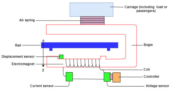
Figure 1.
Suspension system of a displacement, current, and voltage sensor configured electromagnetic system for a Magnetic Levitation (Maglev) train.
We simulate the proposed algorithm for the prototype structure of the voltage-controlled MLS as shown in Figure 2 based on the levitation of a steel ball in which its position () is detected by the position detector and controlled by regulating the coil voltage (). The electromagnet is presented by a series combination of coil resistance () and coil position-dependent inductance ().
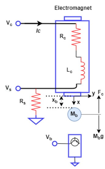
Figure 2.
Diagram illustrates dynamics of the Magnetic Levitation (Maglev) system.
The MLS has two sub-systems: (a) mechanical and (b) electrical [], given as
where electromagnetic force and flux , developed by coil voltage regulation, are the nonlinear function of ball position () and coil current (), and d is the vertical load disturbance. The nominal values of the physical parameters for the MLS are presented in Table 1 [].

Table 1.
Nominal values of simulation parameters.
2.1. Problem Statements
In this research, some critical problems, along with the fundamental issues, like the high-order nonlinearity, open-loop instability, parameter variation, and electromechanical coupling, associated with the MLS, are addressed herein:
- The nonlinear and uncertain dynamics of mechanical and electrical subsystems areThe coil inductance is presented as a function of the ball position using different approximations. is an incremental inductance due to the ball at , a is a length constant, and and are mathematical constants. Some of the widely used approximations are described in Table 2.
 Table 2. Approximations for coil inductance.
 - Using the Wong approximation for the mechanical sub-system, neglecting the coupling inductance, and considering the constant self-inductance () for the electrical sub-system, the nominal mathematical model of MLS is expressed aswhere are the operating constant parameters of MLS, is the adaptive coil voltage that is to be developed by an adaptive control structure, and , are the state variables that represent the steel ball position, vertical velocity, and coil current, respectively.
- The nominal algebraic equations for the parameters associated with the nonlinear model in Equation (5) are given asThese parameters are valid only around the operating conditions (i.e., , , , ) []. It is reported in Reference [] that the MLS possesses a high level of parametric uncertainties. Variation in may cause sticking of the steel ball to the electromagnet or falling, and drift in or from the operating values may cause the burning of coil or actuator saturation.
2.2. Control Objectives
The primary objective in a maglev train is to keep the gap separating the rail and the electromagnet within safe bounds, despite parameter variations. In the prototype MLS, the main control objective is to regulate the steel ball position within the upper and lower safe limits by directing the controller to follow the reference position (). The designed controller needs to drive the coil voltage () within specified constraints to avoid damage to the electromagnet. The following control objectives are needed to be satisfied:
- The steel ball should stay within the safe bounds of m []. In this simulation study, m is considered. Hence, the ball must stay within 0.008–0.010 m under all circumstances.
- The electrical signals, like coil voltage and coil current, should not cross the upper safe limits of +24 V and +2.5 A, respectively, to avoid actuator saturation. The same signals must be maintained positive to avoid the falling of the steel ball, (i.e., ).
- The steel ball should stay within the safe limits specified earlier even during the sudden change in the matched (i.e., ) or mismatched (i.e., ) parameters.
3. Model-Assisted Adaptive Control Design
The fundamental structure of the proposed algorithm contains (a) a reference model, (b) reference model stabilizer, (c) parameter adaption laws, and (d) adaptive control signals, as presented in Figure 3.
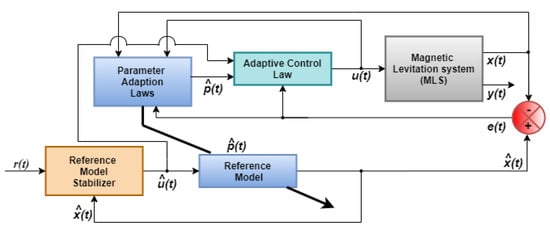
Figure 3.
Model assisted adaptive control structure for Magnetic Levitation System (MLS).
Let us consider an appropriate reference model regulated by the stabilizer as
where are the parameter estimates, is the control action taken by the reference stabilizer described later in Equation (20), and are the reference states.
Subtracting Equation (5) from Equation (7), the tracking-error dynamics with , are given as
where are the parameter error terms, is the square ratio of coil current and ball position, and is the square ratio error. Next, we formulate model-assisted adaptive estimates for appropriate estimation of the reference model parameters in Equation (7):
where are adaptation gains to provide desired control authority over the transient behavior of the error dynamics. Coefficients are also chosen to provide a constrained solution, in such a way that the suffix pertains to the error dynamics Equation (8) in which the parameter error term appears. The adaptive control law is chosen as
where is a tunable control gain parameter. The adaptive update and adaptive control law in Equations (9) and (10) are formulated based on the Lyapunov stability theorem.
Theorem 1
Proof.
Choosing an appropriate positive definite candidate function that encompasses all the tracking and parameter errors, expressed as
where , . By differentiating, we obtain
where , and so The time-derivative vanishes because of the constant magnitude.
Now, substituting and from Equations (8) and (9) into Equation (12), by canceling the terms containing , , and by simplifying , we get
The first two terms of Equation (13) are then expressed as and which represent negative squared terms and other terms that remain after completing the square, given as
Substituting , and the adaptive control law u from Equation (10) into Equation (13), we get
where and represent terms with negative and positive signed coefficients, respectively, given as
To ensure that in Equation (15), one of the ways is to obtain under a combination of parametric constraints (i.e., , and ) . Since there are two squared negative terms in , namely , with the following constraints in place, the remaining two terms would also be negative semi-definite such that :
However, to ensure , we define the upper and lower bound of such that is small compared to , and ∀. Therefore, we have
In Equation (18), when , then all the positive signed terms i.e., and of are cancelled with similar terms in , and . However, when , it is possible to obtain a small positive constant ∈ (i.e., ), which satisfies the following bounds for :
Thus, the proposed adaptive control structure with the constraints derived in Equations (17) and (19) guarantees , and so which from Equation (11) implies that and so . The control signal as given by Equation (10) is also bounded, that is . Next, from Equations (8) and (9), we get that because all the signals which are part of those equations are bounded. Additionally, since is lower bounded by the negative of the squared error signals, the error signals also satisfy the following property, . Note that such a property is not applicable to the parameter error signals in general. In conclusion, since and , the corollary of the Barbalet lemma implies that . □
4. Results and Discussion
Next, we carry out simulation for the proposed adaptive control environment in the MLS (5) with matched (i.e., ) and mismatched (i.e., ) parametric uncertainties using MATLAB/SIMULINK platform. It is reported in various sources [,] that the level of uncertainty in and may be , , and , respectively. The nominal values and the safe bounded values (i.e., maximum and minimum) due to change in operating conditions (i.e., , , , ) are mentioned in Table 3. For this study, the uncertainties are introduced simultaneously in all the parameters (i.e., , and ) with the magnitude of , and , respectively, at s.

Table 3.
Nominal values of parameters and feedback gains.
4.1. Design of Reference Model Stabilizer
Since the MLS is a set of nonlinear and unstable open-loop dynamic system, the reference model in Equation (7) is first stabilized around operating reference position ( m). For this regulation, the reference model stabilizer is designed with the following control law(), given by
In Equation (20), the state control gain and the reference control gain (i.e., , , i = 1, 2, 3) are chosen, such that (a) the reference model ball position () is stabilized around m with the constant values of in less than 2 s, (b) all the state signals and the control signal stay within the safe operative limits in the presence of nominal payload disturbance () of 10%. Using the widely used LQR control technique, the reference stabilizer is designed with the gains mentioned in Table 3. The response of state variables and the control variable at the initial ball position of m with above gains and without payload disturbance is shown in Figure 4.
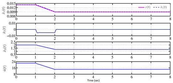
Figure 4.
Response of reference model variables driven by the stabilizer without disturbance.
The mathematical model of the MLS is valid only if the change in the parameters are in between the bound shown in Table 3. In physical systems, it is a reasonable assumption to make that the parameters will lie within certain bounds. However, the values of the parameters may change within those bounds.
The estimated ball position smoothly tracks the reference signal . The resulting outputs of the signals associated with the reference system lies within a safe region (i.e., ). For the Maglev trains, the track irregularities, as well as the payload disturbance, is expressed by the slow-varying sinusoidal pattern. Next, the mismatched type of external payload variation in the (0–10)% range with the sinusoidal pattern is chosen as . The response of and the control variable () in the presence of (0–10)% sinusoidal payload disturbance from s using the reference stabilizer with above gains, is provided in Figure 5.
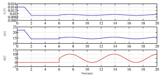
Figure 5.
Response of reference model driven by the stabilizer in the presence of sinusoidal payload disturbance.
From s, the ball position has been shifted from . Due to change in the stable position, the reference stabilizer has manipulated the coil voltage such that the ball should stay within (0.008–0.010) m and coil voltage should stay within 0–24 V. Hence, the designed stabilizer is capable to achieve the control objectives of the MLS with or without external mismatched disturbances. When sudden change occurs in ball mass, the curves of the coil current and voltage and ball position are depicted in Figure 6 and Figure 7. The sudden change in ball mass up to , ball position, coil current, and coil voltage are still sustained in between its safe bounds. While it is true that sudden change in the mass of the ball is not practically observable in a laboratory setup, like the Quanser Magnetic Levitation systems, we consider such a situation in this simulation study as an extreme condition. The challenge of meeting the control objective is most challenging in such conditions of transience. The simulation results show that the controller design presented is robust to such extreme conditions, as well.
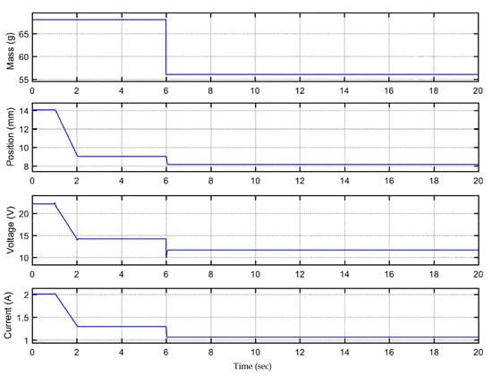
Figure 6.
Response of coil voltage, coil current with sudden increment of 15% in mass of steel ball.
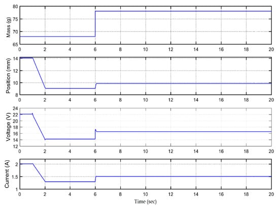
Figure 7.
Response of coil voltage, coil current with sudden drop of 15% in mass of steel ball.
4.2. Design of Parameter Adaptation Mechanism
As stated earlier, in a long duration service or due to fault in MLS, the parameters may change. Once the reference system is stabilized around with or without disturbances, the next task is to develop the parameter adaptation laws. This mechanism consists of (a) tracking-error dynamics , (b) parameter estimation dynamics and (c) adaptive control law () for as described in Equations (8)–(10), respectively.
This mechanism is designed such that all the tracking-errors converge to zero asymptotically. In addition, the parameter estimates () converge to the steady-state values within the bounds mentioned in Table 3 and satisfy the constraints obtained in Equations (17) and (19). The Lyapunov stability analysis (Theorem 1) is utilized to obtain the parameter constraints and to choose the tuning parameters (i.e., , ). The chosen values of such tuning parameters are presented in Table 4. Using these values, the tracking-error dynamics are stabilized around zero as shown in Figure 8. There are periodic oscillations and damping in the response of and in the initial phase for 2 to 3 s from . This phenomenon can be co-related with the nonlinear second-order under-damped nature of the mechanical sub-system of the MLS []. The proposed controller can adapt to the change, which is introduced at 4 s and ensures convergence of the error between the two responses to zero within a short time of 2 s. The error, which was already zero before the change in parameters, re-converges to zero after short transience, thereby demonstrating the controller’s robustness, as shown in Figure 8. That is, the tracking error is dynamically stable around the 0, and it is at zero except for a brief period of transience immediately following the change in parameters.

Table 4.
Nominal values of tuning parameters based on Theorem 1.
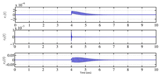
Figure 8.
Response of tracking-errors under parametric uncertainties ().
It is equally important to get the bounded steady-state response of the estimated parameters () of the reference model. Hence, using the heuristic approach and the knowledge of the MLS, the parametric update laws in Equation (9) and the control law in Equation (10) have been tuned. The response of estimated parameters are shown in Figure 9.
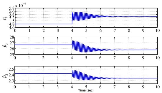
Figure 9.
Response of satisfying the bounds mentioned in Table 3.
The oscillations and damping are observed in the response of due to the presence of tracking-errors in the dynamics of parameter update laws in Equation (9). It is necessary to obtain the regulatory response of the MLS in the presence of parametric violation. During this process, the gains (i.e., ) of adaptive control law() in Equation (10) are required to tune around their optimal values to satisfy the constraint in Equation (17).
The responses of state-variables and control action around under parametric uncertainties introduced from are shown in Figure 10. Note that all the variables are asymptotically stabilized within their respective safe limits prescribed as per the control objectives. The steel-ball has shown under-damped velocity response for 2 s after introducing the uncertainties which may be the prime source of oscillatory behaviour of estimated parameters and tracking-error dynamics. However, it is damped out at around s by the control action of designed adaptive mechanism. The constraints in Figure 11 for the estimated parameters derived in Theorem are satisfied to obtain as shown in Figure 12 using the obtained values of , and for .
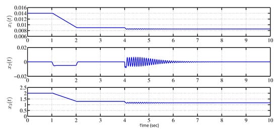
Figure 10.
Response of state-variables of MLS under parametric uncertainties ().
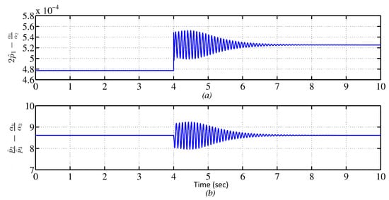
Figure 11.
Satisfaction of the constraints in Equation (17): .
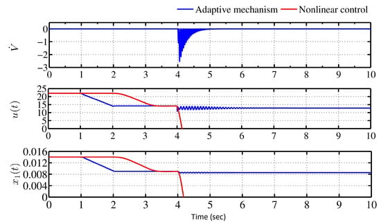
Figure 12.
Response of , control action , and ball position with parametric uncertainties.
Finally, the system (5) is tuned with one of the widely used Feedback Linearizing Control (FLC) approach for the nonlinear dynamical MLS with the lumped parametric uncertainties. The nonlinear controller (i.e., FLC) fails to regulate the MLS. The comparative response of the steel-ball position and control action using the adaptive mechanism and the nonlinear control are shown in Figure 12. The nonlinear control approach has shown permanent failure in regulating the MLS via coil-voltage. However, the proposed adaptive mechanism has retrieved the ball’s stable levitation around the reference position (r = 0.009 m) by manipulating the coil-voltage, in the presence of uncertainties (including abrupt ones) shown in Figure 10.
5. Concluding Remarks
Significant parameter variations result in performance degradation in MLS. Therefore, we present the design and implementation framework of a model-assisted adaptive controller for MLS. The proposed design compensates both the matched and mismatched lumped parametric uncertainties up to . This study introduces a nonlinear reference model governed by a reference stabilizer appropriately tuned against time-varying payload disturbance. We then derive the tracking-error dynamics. The Lyapunov stability analysis is formulated for the closed-loop MLS to obtain the adaptive parameter update estimations and the control signals. The design constraints associated with the physical structure are fully satisfied by the proposed framework such that the required convergence for the tracking-errors and the estimated parameters are attainable. The adaptive mechanism is confirmed to be effective under uncertain parametric conditions. The MLS retrieves the stable levitation in less than 2 s using the proposed framework. However, the nonlinear controller results in permanent failure with the ball falling from the post, thereby validating that the proposed adaptive control strategy significantly increases the MLS’ robust performance and aids in control parameter monitoring in maglev transportation systems.
A typical MLS system in a laboratory does not account for abrupt changes in parameters. As a future work, validation though an appropriate experimentation that can account for abrupt changes will require extensive hardware development in the laboratory. This subsequent work with experimental results can be reported to this journal in a separate manuscript when ready.
Author Contributions
Conceptualization, D.D.; methodology, D.D. and N.D.; software, N.D.; validation, N.D.; formal analysis, D.D.; writing—original draft preparation, N.D. and S.M.M.; writing—review and editing, D.D. and S.M.M; supervision, D.D.; funding acquisition, S.M.M. All authors have read and agreed to the published version of the manuscript.
Funding
This research received no external funding.
Acknowledgments
The authors acknowledge Ravi Gandhi’s contributions. The first author had several discussions with him which has largely benefited this work.
Conflicts of Interest
The authors declare no conflict of interest.
References
- Lee, H.; Kim, K.; Lee, J. Review of Maglev Train Technologies. IEEE Trans. Magn. 2006, 42, 1917–1925. [Google Scholar]
- Kim, S.K. Nonlinear position stabilizing control with active damping injection technique for magnetic levitation systems. Electronics 2019, 8, 221. [Google Scholar] [CrossRef]
- Zhang, W.; Wei, W.; Yang, Y.; Nan, N. An Operation Control Strategy for the Connected Maglev Trains Based on Vehicle-Borne Battery Condition Monitoring. Wirel. Commun. Mob. Comput. 2018, 2018, 1–10. [Google Scholar] [CrossRef]
- Zhang, Z.; Li, X. Real-Time Adaptive Control of a Magnetic Levitation System with a Large Range of Load Disturbance. Sensors 2018, 18, 1512. [Google Scholar] [CrossRef]
- Sinha, P.K. Dynamics of magnetically suspended vehicles. Trans. Inst. Meas. Control 1979, 1, 57–64. [Google Scholar] [CrossRef]
- Liu, Z.; Long, Z.; Li, X. Maglev Trains Key Underlying Technologies; Springer Tracts in Mechanical Engineering: Berlin/Heidelberg, Germany, 2015; pp. 1–224. [Google Scholar]
- Amrhein, W.; Gruber, W.; Bauer, W.; Reisinger, M. Magnetic Levitation Systems for Cost-Sensitive Applications — Some Design Aspects. IEEE Trans. Fuzzy Syst. 2016, 52, 3739–3752. [Google Scholar] [CrossRef]
- Yaghoubi, H. The most important Maglev applications. J. Eng. 2013, 2013, 1–19. [Google Scholar] [CrossRef]
- Park, Y. Design and implementation of an electromagnetic levitation system for active magnetic bearing wheels. IET Control Theory Appl. 2014, 8, 139–148. [Google Scholar] [CrossRef]
- Banerjee, S.; Pal, J.; Prasad, D. Performance study of the controller of an attraction type levitation system under parametric change. J. Electr. Syst. 2010, 3, 377–394. [Google Scholar]
- Ghosh, A.; Krishnan, T.R.; Tejaswy, P.; Mandal, A.; Pradhan, J.; Ranasingh, S. Design and implementation of a 2-DOF PID compensation for magnetic levitation systems. ISA Trans. 2014, 53, 1216–1222. [Google Scholar] [CrossRef]
- Gandhi, R.; Adhyaru, D. Hybrid intelligent controller design for an unstable electromagnetic levitation system: A fuzzy interpolative controller approach. Int. J. Control Autom. 2019, 13, 735–754. [Google Scholar] [CrossRef]
- Folea, S.; Muresan, C.; De Keyser, R.; Ionescu, C. Theoretical Analysis and Experimental Validation of a Simplified Fractional Order Controller for a Magnetic Levitation System. IEEE Trans. Control Syst. Technol. 2016, 24, 756–763. [Google Scholar] [CrossRef]
- Wai, R.J.; Lee, J.D.; Chuang, K.L. Real-time PID control strategy for maglev transportation system via particle swarm optimization. IEEE Trans. Ind. Electron. 2011, 58, 629–646. [Google Scholar] [CrossRef]
- Yang, Z.J.; Miyazaki, K.; Kanae, S.; Wada, K. Robust Position Control of a Magnetic Levitation System via Dynamic Surface Control Technique. IEEE Trans. Ind. Electron. 2004, 51, 26–34. [Google Scholar] [CrossRef]
- Kai, C.Y.; Huang, A.C. Adaptive control of magnetic levitation system subject to external disturbances. J. Chin. Inst. Eng. 2016, 39, 513–520. [Google Scholar] [CrossRef]
- Bidikli, B.; Bayrak, A. A self-tuning robust full-state feedback control design for the magnetic levitation system. Control Eng. Pract. 2018, 78, 175–185. [Google Scholar] [CrossRef]
- Xu, J. Adaptive robust constrained state control for non-linear maglev vehicle with guaranteed bounded airgap. IET Control Theory Appl. 2018, 12, 1573–1583. [Google Scholar] [CrossRef]
- Eroǧlu, Y.; Ablay, G. Cascade sliding mode-based robust tracking control of a magnetic levitation system. Proc. Inst. Mech. Eng. Part I J. Syst. Control Eng. 2016, 230, 851–860. [Google Scholar] [CrossRef]
- Gandhi, R.; Adhyaru, D. Takagi-Sugeno Fuzzy Regulator Design for Nonlinear and Unstable Systems using Negative Absolute Eigenvalue Approach. IEEE J. Autom. Sin. 2020, 7, 1–14. [Google Scholar] [CrossRef]
- Joo, S.; Seo, J. Design and analysis of the nonlinear feedback linearizing control for an electromagnetic suspension system. IEEE Trans. Control Syst. Technol. 1997, 5, 135–144. [Google Scholar]
- Barie, W.; Chaisson, J. Linear and nonlinear state-space controllers for magnetic levitation. Int. J. Syst. Sci. 1996, 27, 1153–1163. [Google Scholar] [CrossRef]
- Zhang, L. Hybrid non-linear differentiator design for a permanent-electro magnetic suspension maglev system. IET Signal Process. 2012, 6, 559–567. [Google Scholar] [CrossRef]
- Back, J. Reduced-order implementation of disturbance observers for robust tracking of non-linear systems. IET Control Theory Appl. 2014, 8, 1940–1948. [Google Scholar] [CrossRef]
- Chen, X.; Li, J.; Yang, J.; Li, S. A disturbance observer enhanced composite cascade control with experimental studies. Int. J. Control. Autom. Syst. 2013, 11, 555–562. [Google Scholar] [CrossRef]
- Zhou, W.; Liu, B. Backstepping Based Adaptive Control of Magnetic Levitation System. Appl. Mech. Mater. 2013, 342, 945–948. [Google Scholar] [CrossRef]
- Lin, F.J.; Teng, L.T.; Shieh, P.H. Intelligent adaptive backstepping control system for magnetic levitation apparatus. IEEE Trans. Magn. 2007, 43, 2009–2018. [Google Scholar] [CrossRef]
- Zhai, M.; Long, Z.; Li, X. A new strategy for improving the tracking performance of magnetic levitation system in maglev train. Symmetry 2019, 11, 1053. [Google Scholar] [CrossRef]
- Adıgüzel, F.; Dokumacılar, E.; Akbatı, O.; Türker, T. Design and implementation of an adaptive backstepping controller for a magnetic levitation system. Trans. Inst. Meas. Control 2018, 40, 2466–2475. [Google Scholar] [CrossRef]
- Al-Araji, A.S. Cognitive non-linear controller design for magnetic levitation system. Trans. Inst. Meas. Control 2016, 38, 215–222. [Google Scholar] [CrossRef]
- Radac, M.; Precup, R.; Hedrea, E.; Tănăsoiu, O. Gain-Scheduling Control Solutions for Magnetic Levitation Systems. Acta Polytech. Hung. 2018, 15, 89–108. [Google Scholar]
- Deb, D.; Tao, G.; Smith, D.R. Adaptive Compensation Control of Synthetic Jet Actuator Arrays for Airfoil Virtual Shaping. J. Aircr. 2007, 44, 616–626. [Google Scholar] [CrossRef]
- Deb, D.; Tao, G.; Burkholder, J.O.; Smith, D.R. Adaptive Synthetic Jet Actuator Compensation for A Nonlinear Aircraft Model at Low Angles of Attack. IEEE Trans. Control Syst. Technol. 2008, 16, 983–995. [Google Scholar] [CrossRef]
- Nath, A.; Deb, D.; Dey, R.; Das, S. Blood glucose regulation in type 1 diabetic patients: An adaptive parametric compensation control-based approach. IET Syst. Biol. 2018, 12, 219–225. [Google Scholar] [CrossRef] [PubMed]
- Nath, A.; Deb, D.; Dey, R. An augmented subcutaneous type 1 diabetic patient modelling and design of adaptive glucose control. J. Process Control 2020, 86, 94–105. [Google Scholar] [CrossRef]
- Jacob, E. Quanser Magnetic Levitation User Manual. Available online: file:///C:/Users/MDPI/AppData/Local/Temp/made-for-science-Quanser-magnetic-levitation-CoursewareStud-MATLAB.pdf (accessed on 12 October 2020).
- Wong, T.H. Design of a magnetic levitation control system undergraduate project. IEEE Trans. Educ. 1986, E-29, 196–200. [Google Scholar] [CrossRef]
- Woodson, H.; Melcher, J. Electromechanical Dynamics; John Wiley & Sons: Sydney, Australia, 1968; pp. 1–414. [Google Scholar]
- Hurley, W.; Wölfle, W. Electromagnetic design of a magnetic suspension system. IEEE Trans. Educ. 1997, 40, 124–130. [Google Scholar] [CrossRef]
- Gandhi, R.; Adhyaru, D. Novel approximation-based dynamical modelling and nonlinear control of electromagnetic levitation system. Int. J. Comput. Syst. Eng. 2018, 4, 224–237. [Google Scholar] [CrossRef]
- Wei, W.; Xue, W.; Li, D. On disturbance rejection in magnetic levitation. Control Eng. Pract. 2019, 82, 24–35. [Google Scholar] [CrossRef]
- Banerjee, S.; Prasad, D.; Pal, J. Large gap control in electromagnetic levitation. ISA Trans. 2006, 45, 215–224. [Google Scholar] [CrossRef]
- Goodall, R. Dynamic characteristics in the design of MAGLEV suspensions. J. Rail Rapid Transitinst. Mech. Eng. 1994, 208, 33–41. [Google Scholar] [CrossRef]
- Godbole, A.A.; Kolhe, J.P.; Talole, S.E. Performance Analysis of Generalized Extended State Observer in Tackling Sinusoidal Disturbances. IEEE Trans. Control Syst. Technol. 2013, 21, 2212–2223. [Google Scholar] [CrossRef]
Publisher’s Note: MDPI stays neutral with regard to jurisdictional claims in published maps and institutional affiliations. |
© 2021 by the authors. Licensee MDPI, Basel, Switzerland. This article is an open access article distributed under the terms and conditions of the Creative Commons Attribution (CC BY) license (http://creativecommons.org/licenses/by/4.0/).