
A Sub-6 GHz MIMO Antenna Array for 5G Wireless Terminals


Abstract
:1. Introduction
2. Antenna Geometry
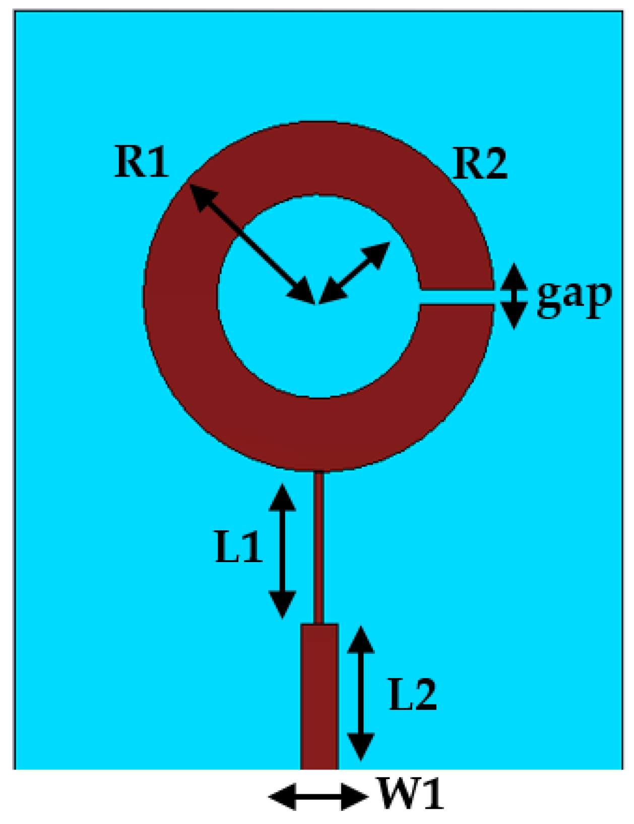
2.1. Single Element
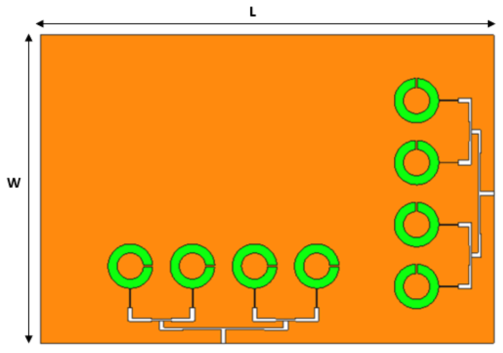
2.2. Multiple-Element Antenna Array
2.3. MIMO Configuration
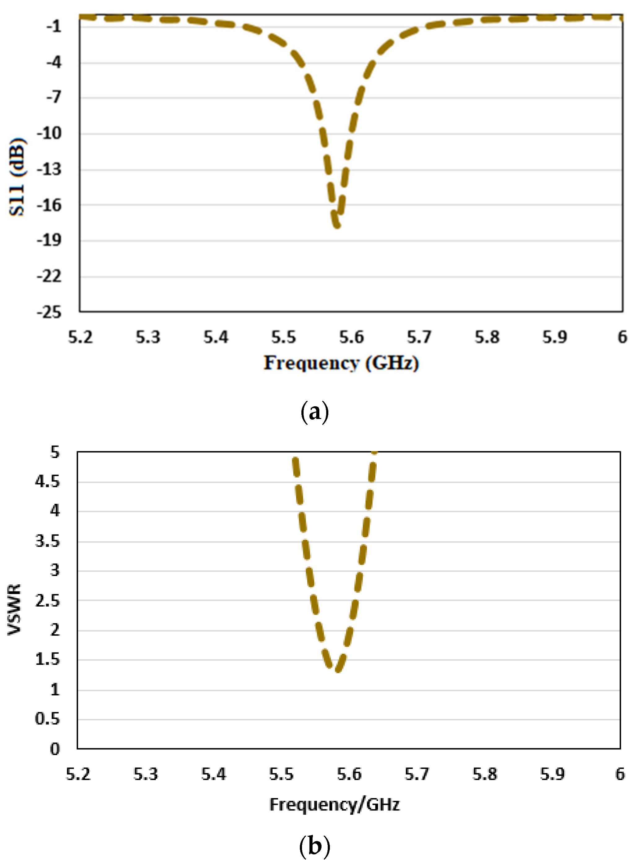
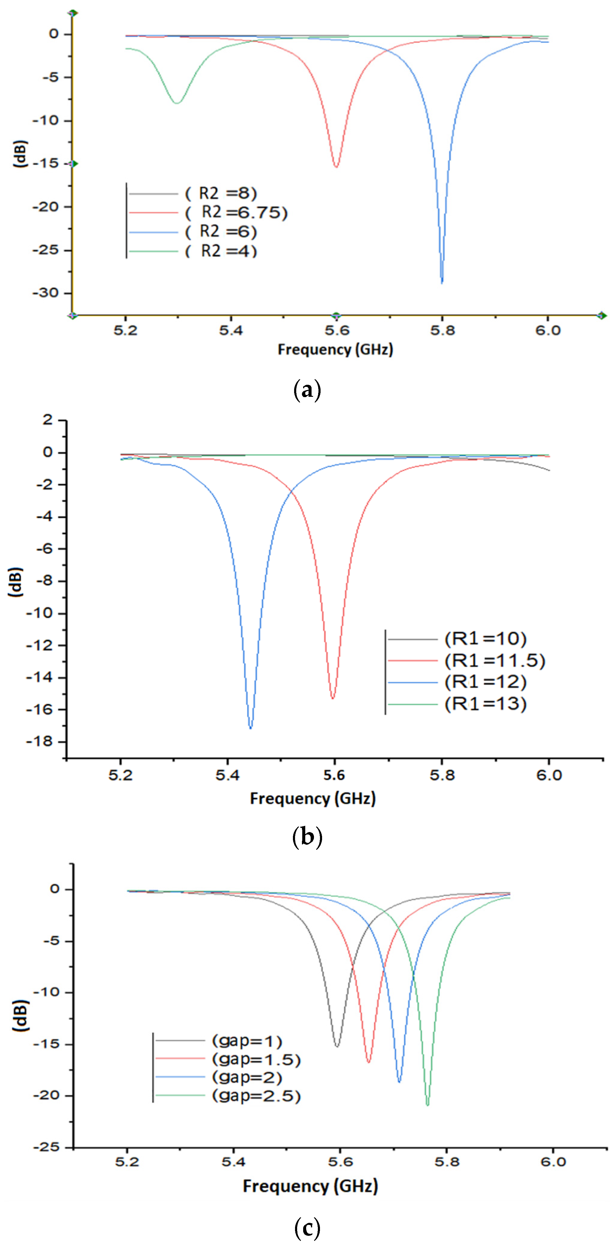
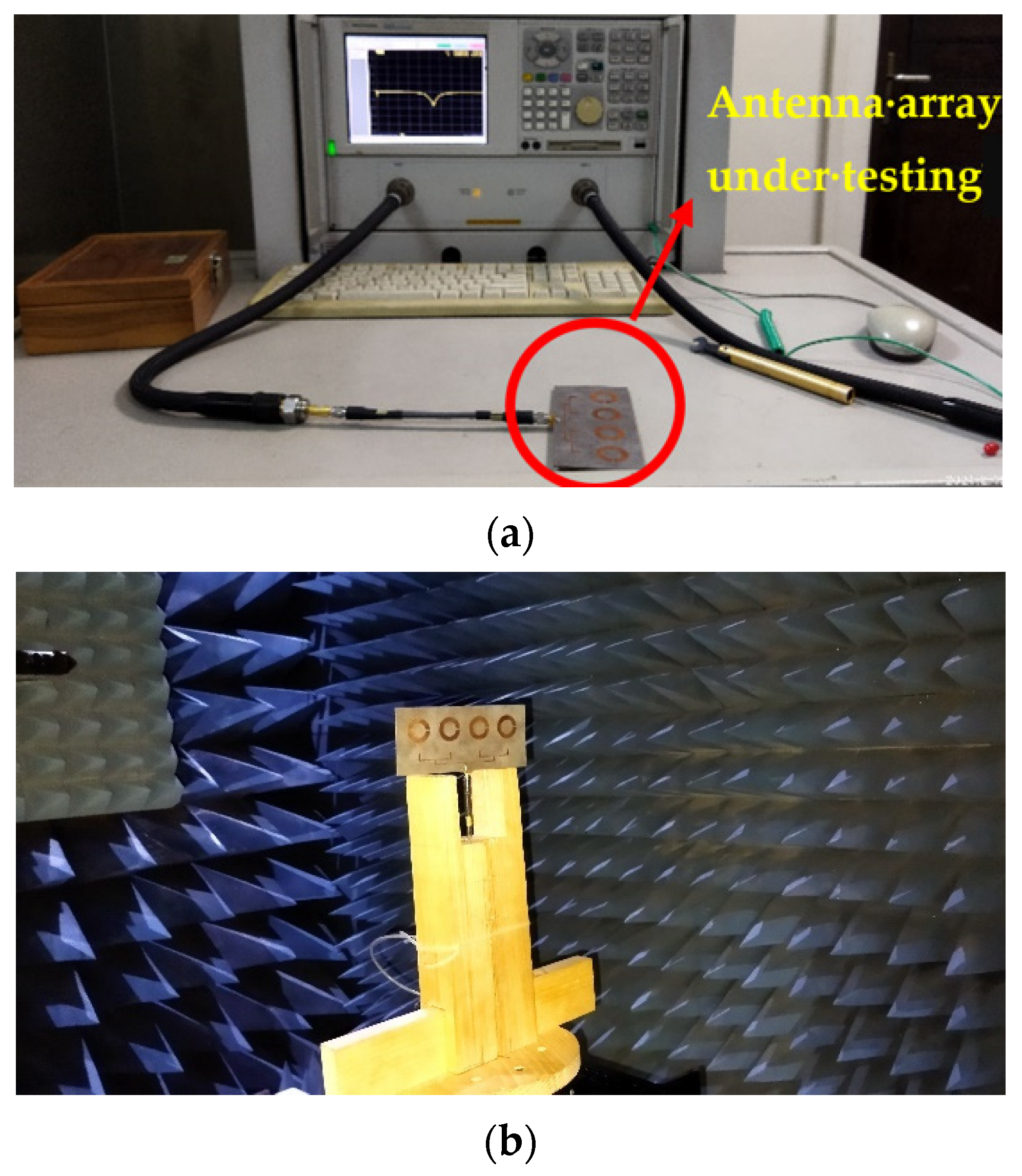
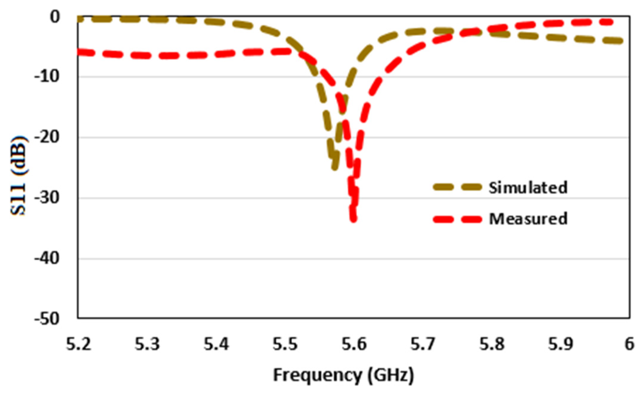
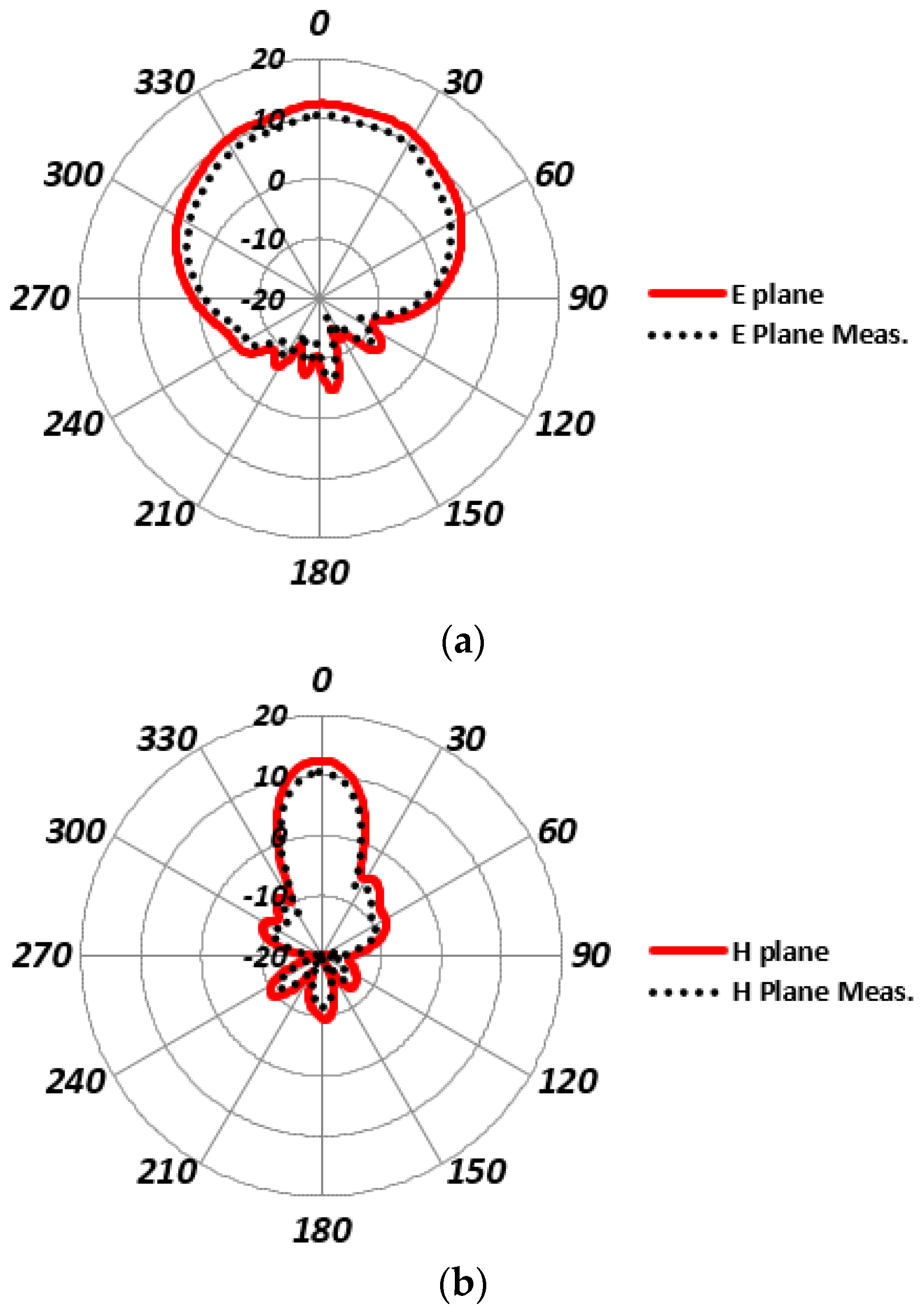
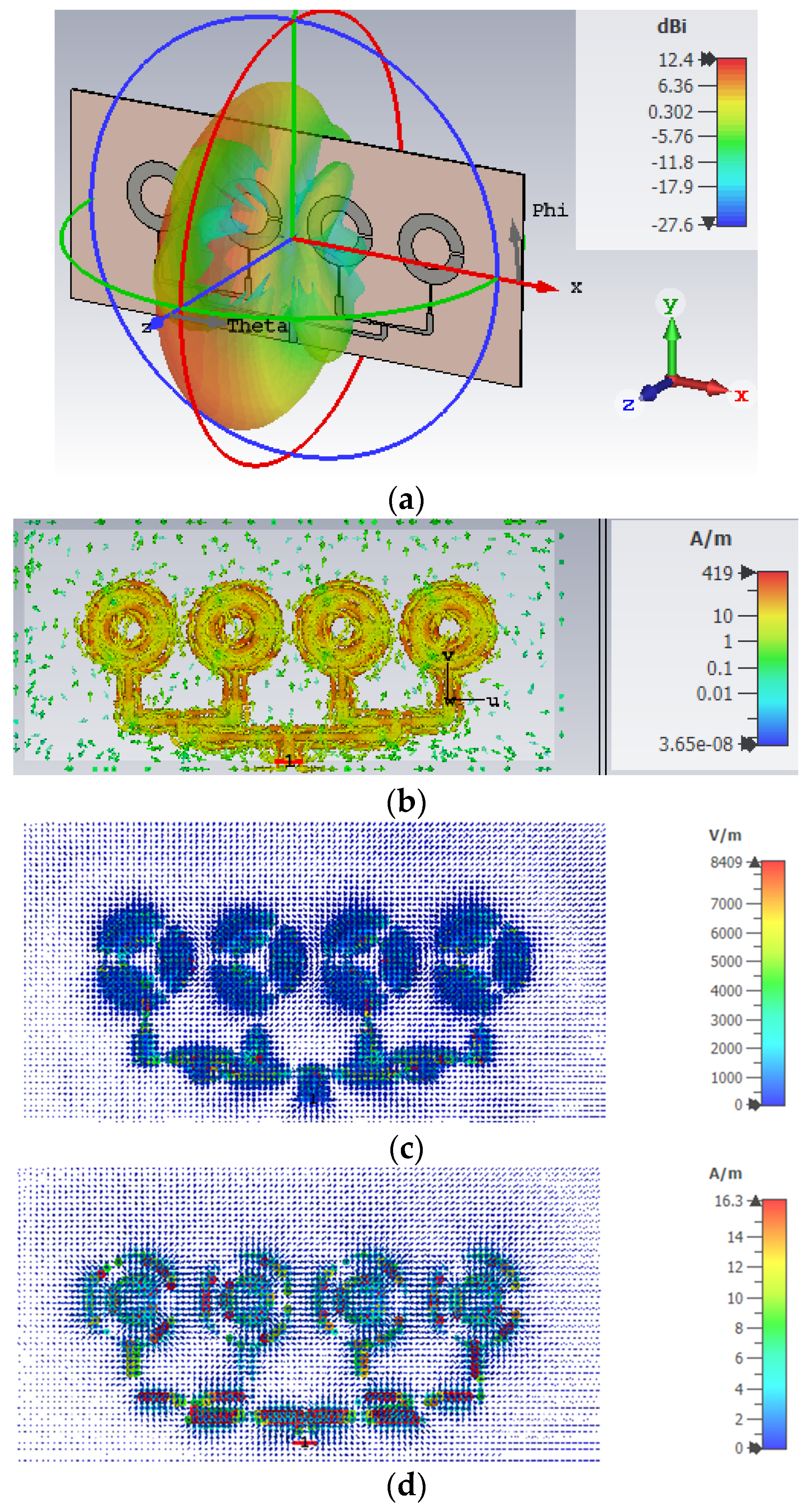
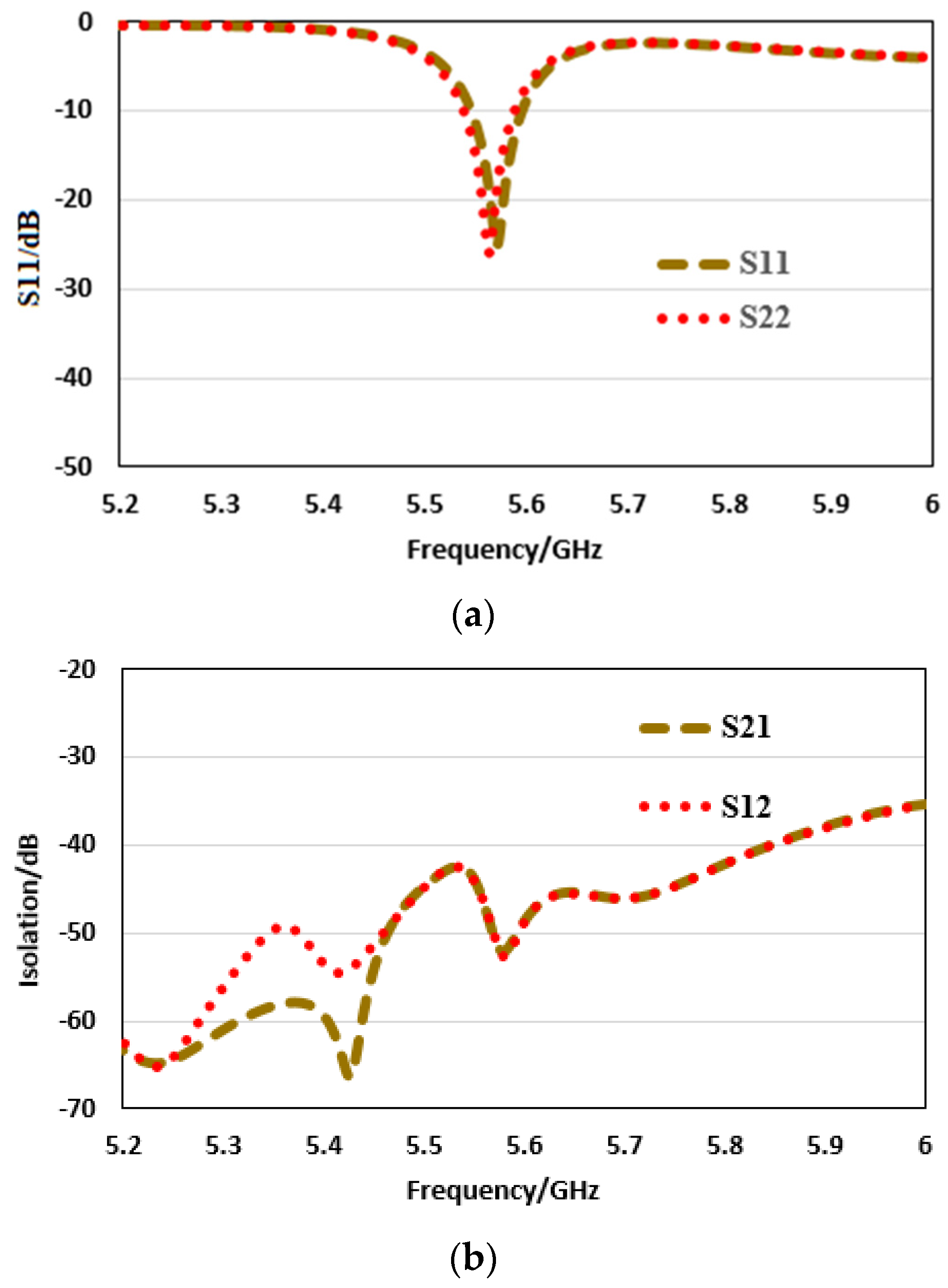
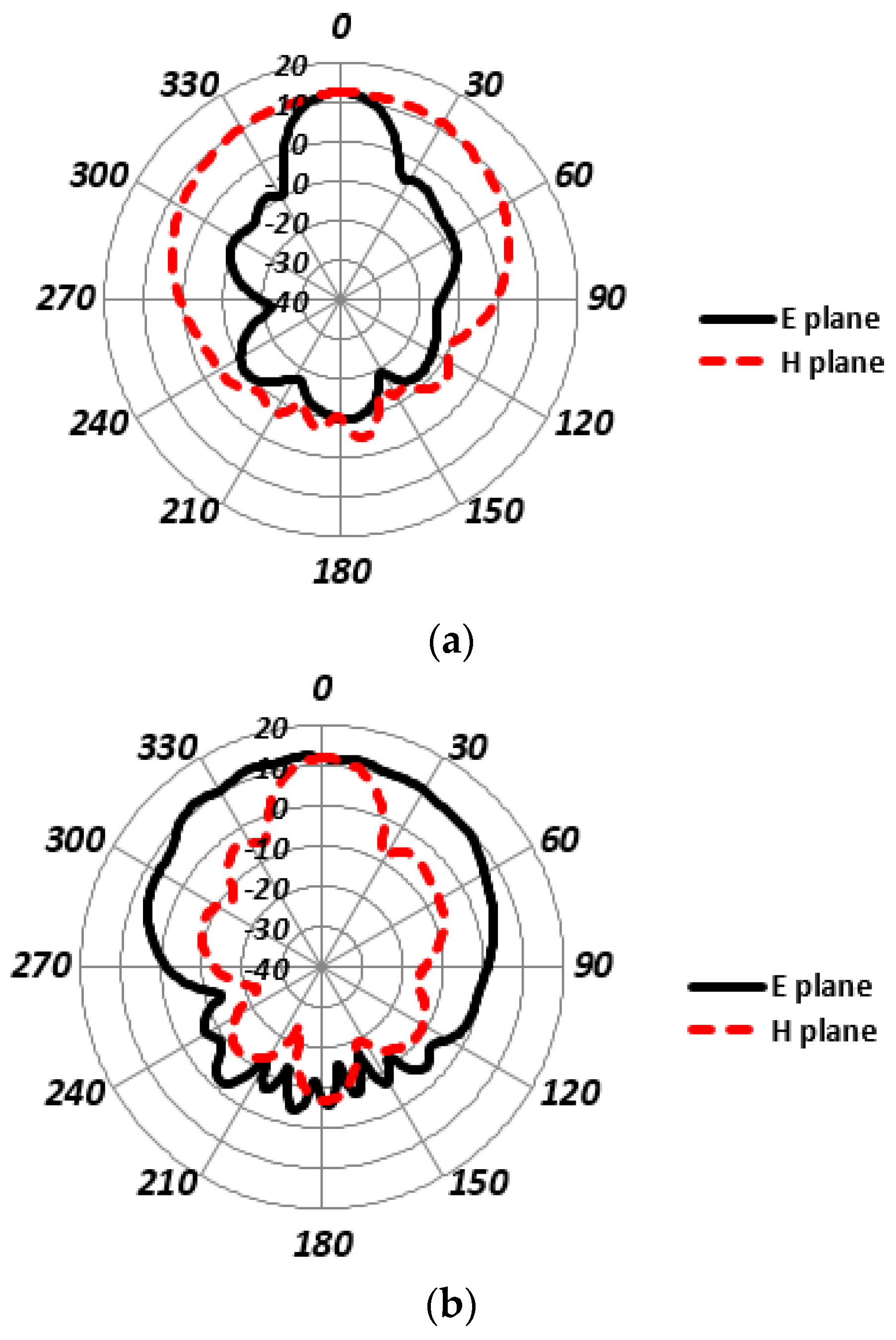
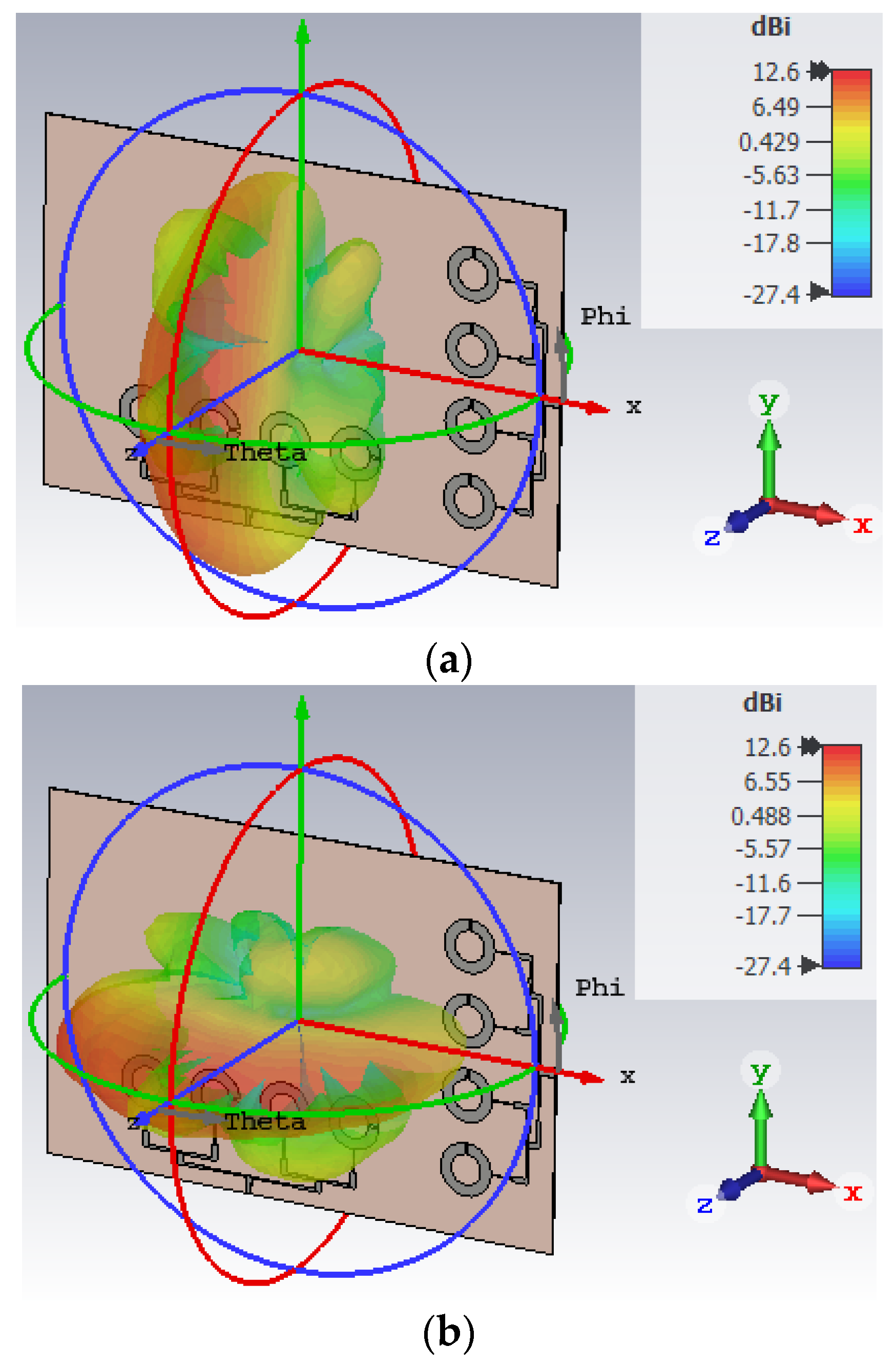
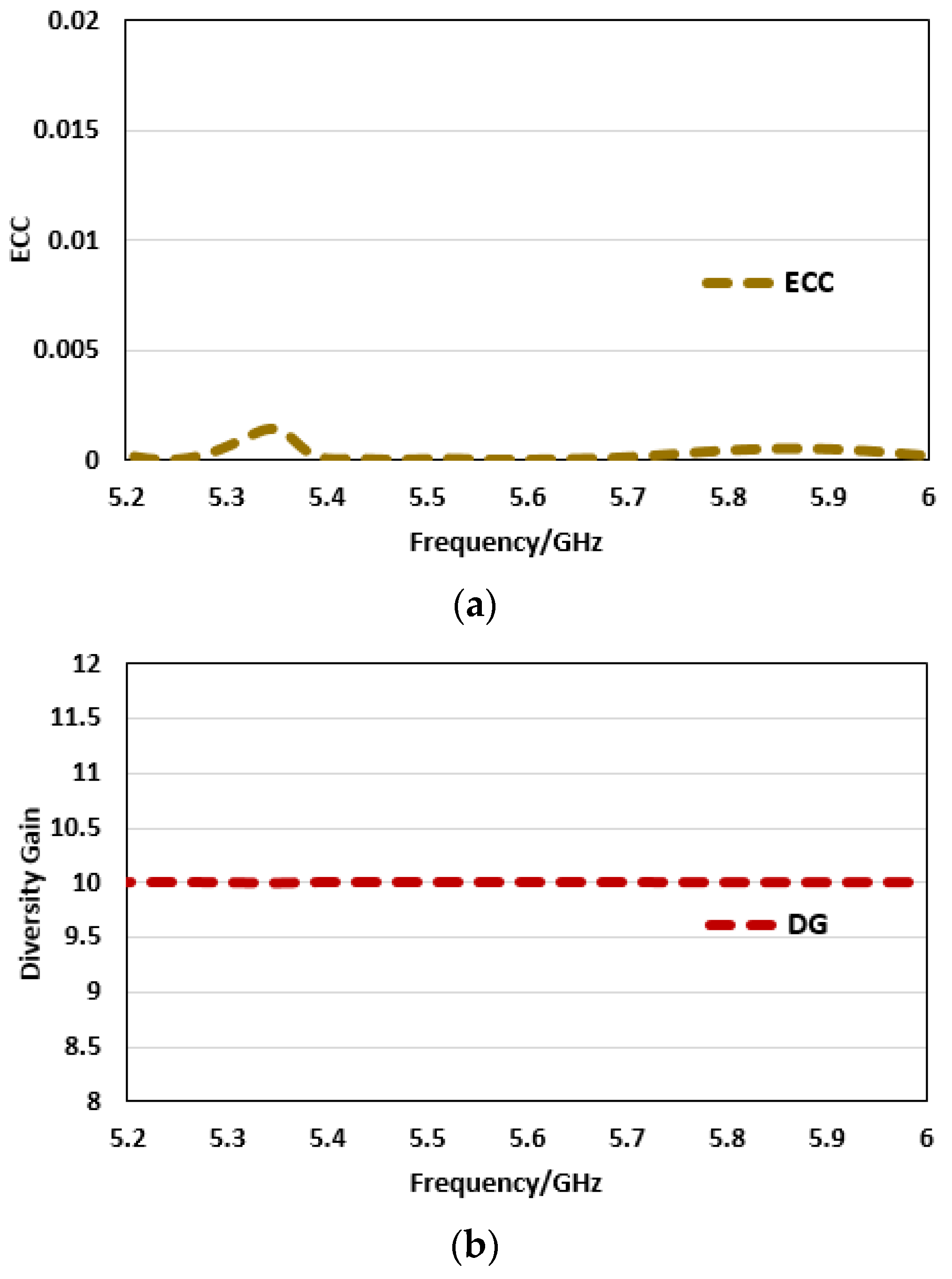
3. Results and Discussion
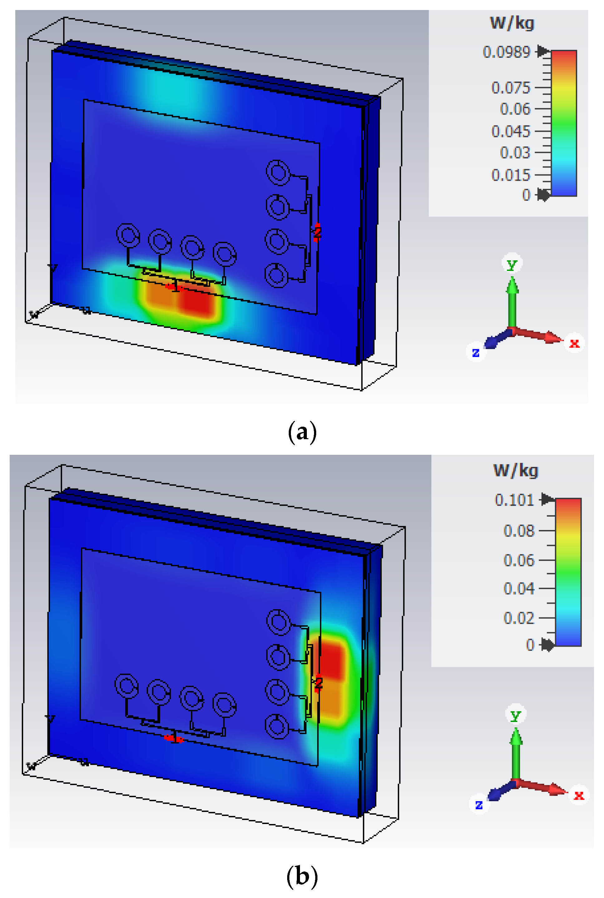
4. SAR Analysis for the Proposed MIMO Antenna
5. Conclusions
Author Contributions
Funding
Institutional Review Board Statement
Informed Consent Statement
Data Availability Statement
Conflicts of Interest
References
- Khan, J.; Sehrai, D.A.; Khan, M.A.; Khan, H.A.; Ahmad, S.; Ahmad, S.; Ali, A.; Arif, A.; Memon, A.A.; Khan, S. Design and performance comparison of rotated Y-shaped antenna using different metamaterial surfaces for 5G mobile devices. Comput. Mater. Contin. 2019, 2, 409–420. [Google Scholar] [CrossRef]
- Sharaf, M.H.; Zaki, A.I.; Hamad, R.K.; Omar, M.M.M. A Novel Dual-Band (38/60 GHz) Patch Antenna for 5G Mobile Handsets. Sensors 2020, 20, 2541. [Google Scholar] [CrossRef] [PubMed]
- Barreto, A.N.; Faria, B.; Almeida, E.; Rodriguez, I.; Lauridsen, M.; Amorim, R.; Vieira, R. 5G–Wireless Communications for 2020. J. Commun. Inf. Syst. 2016, 31, 146–163. [Google Scholar] [CrossRef] [Green Version]
- Patnaik, P.; Sarkar, D.; Saha, C. A multi-band 5G antenna for Smart phones operating at Sub-6 GHz frequencies. In Proceedings of the IEEE International Symposium on Antennas & Propagation (APSYM), Cochin, India, 14–16 December 2020; pp. 32–35. [Google Scholar]
- Nam, H.J.; Lim, S.; Yoon, Y.J.; Kim, H. Tunable triple-band antenna for Sub-6 GHz 5G mobile phone. In Proceedings of the IEEE International Symposium on Antennas and Propagation and North American Radio Science Meeting, Montreal, QC, Canada, 5–10 July 2020; pp. 1455–1456. [Google Scholar]
- Jiang, J.; Li, Y. A wideband kanji patch antenna for 5G Sub-6-GHz applications. In Proceedings of the IEEE 13th UK-Europe-China Workshop on Millimetre-Waves and Terahertz Technologies (UCMMT), Tianjin, China, 29 August–1 September 2020; pp. 1–2. [Google Scholar]
- Ghaffar, A.; Li, X.J.; Ahmad, T.; Hussain, N.; Alibakhshikenari, M.; Limiti, E. Circularly polarized pattern reconfigurable flexible antenna for 5G-sub-6-GHz applications. In Proceedings of the IEEE Asia-Pacific Microwave Conference (APMC), Hong Kong, China, 8–11 December 2020; pp. 625–627. [Google Scholar]
- Zhao, X.; Yeo, S.P.; Ong, L.O. Decoupling of inverted-F antennas with high-order modes of ground plane for 5G mobile MIMO platform. IEEE Trans. Antennas Propag. 2017, 66, 4485–4495. [Google Scholar] [CrossRef]
- Li, M.Y.; Xu, Z.Q.; Ban, Y.L.; Sim, C.Y.D.; Yu, Z.F. Eight-port orthogonally dual-polarized MIMO antenna using loop structures for 5G smartphone. IET Microw. Antennas Propag. 2017, 11, 1810–1816. [Google Scholar] [CrossRef]
- Li, M.Y.; Ban, Y.L.; Xu, Z.Q.; Guo, J.; Yu, Z.F. Tri-polarized 12-Antenna MIMO array for future 5G smartphone applications. IEEE Access 2017, 6, 6160–6170. [Google Scholar] [CrossRef]
- Jiang, W.; Cui, Y.; Liu, B.; Hu, W.; Xi, Y. A dual-band MIMO antenna with enhanced isolation for 5G smartphone applications. IEEE Access 2019, 7, 112554–112563. [Google Scholar] [CrossRef]
- Li, H.; Tsiaras, A.; Lau, B.K. Analysis and estimation of MIMO-SAR for multi-antenna mobile handsets. IEEE Trans. Antennas Propag. 2017, 65, 1522–1527. [Google Scholar] [CrossRef] [Green Version]
- Li, M.Y.; Li, C.; Ban, Y.L.; Kang, K. Multiple antennas for future 4G/5G smartphone applications. In Proceedings of the 2016 IEEE MTT-S International Microwave Workshop Series on Advanced Materials and Processes for RF and THz Applications (IMWS-AMP), Chengdu, China, 20–22 July 2016. [Google Scholar]
- Ojaroudiparchin, N.; Shen, M.; Pedersen, G.F. Beam-steerable microstrip-fed bow-tie antenna array for fifth generation cellular communications. In Proceedings of the IEEE 10th European Conference on Antennas and Propagation (EuCAP), Davos, Switzerland, 10–15 April 2016; pp. 1–5. [Google Scholar]
- Li, Y.; Zou, H.; Wang, M.; Peng, M.; Yang, G. Eight-element MIMO antenna array for 5G/Sub-6GHz indoor micro wireless access points. In Proceedings of the IEEE International Workshop on Antenna Technology (iWAT), Nanjing, China, 5–7 March 2018; pp. 1–4. [Google Scholar]
- Ren, Z.; Wu, S.; Zhao, A. Triple band MIMO antenna system for 5G mobile terminals. In Proceedings of the IEEE International Workshop on Antenna Technology (iWAT), Miami, FL, USA, 3–6 March 2019; pp. 163–165. [Google Scholar]
- Sim, C.; Liu, H.; Huang, C. Wideband MIMO antenna array design for future mobile devices operating in the 5G NR frequency bands n77/n78/n79 and LTE band 46. IEEE Antennas Wirel. Propag. Lett. 2020, 19, 74–78. [Google Scholar] [CrossRef]
- Li, Y.; Sim, C.Y.D.; Luo, Y.; Yang, G. 12-Port 5G Massive MIMO antenna array in sub-6GHz mobile handset for LTE bands 42/43/46 applications. IEEE Access 2017, 6, 344–354. [Google Scholar] [CrossRef]
- Guo, J.; Cui, L.; Li, C.; Sun, B. Side-edge frame printed eight-port dual-band antenna array for 5G smartphone applications. IEEE Trans. Antennas Propag. 2018, 66, 7412–7417. [Google Scholar] [CrossRef]
- Li, Y.; Yang, G. Dual-mode and triple-band 10-antenna handset array and its multiple-input multiple-output performance evaluation in 5G. Int. J. RF Microw. Comput. Aided Eng. 2019, 29, e21538. [Google Scholar] [CrossRef]
- Zhang, X.; Li, Y.; Wang, W.; Shen, W. Ultra-wideband 8-port MIMO antenna array for 5G metal-frame smartphones. IEEE Access 2019, 7, 72273–72282. [Google Scholar] [CrossRef]
- Cai, Q.; Li, Y.; Zhang, X.; Shen, W. Wideband MIMO antenna array covering 3.3–7.1 GHz for 5G metal-rimmed smartphone applications. IEEE Access 2019, 7, 142020–142084. [Google Scholar] [CrossRef]
- Sun, L.; Li, Y.; Zhang, Z.; Feng, Z. Wideband 5G MIMO antenna with integrated orthogonal-mode dual-antenna pairs for metal-rimmed smartphones. IEEE Trans. Antennas Propag. 2020, 68, 2494–2503. [Google Scholar] [CrossRef]
- Chen, H.; Tsai, Y.; Sim, C.; Kuo, C. Broadband eight-antenna array design for Sub-6 GHz 5G NR bands metal-frame smartphone applications. IEEE Antennas Wirel. Propag. Lett. 2020, 19, 1078–1082. [Google Scholar] [CrossRef]
- Ballanis, C.A. Antenna Theory Analysis and Design; John Willey and Son’s Inc.: New York, NY, USA, 2016. [Google Scholar]
- Khan, J.; Sehrai, D.A.; Ali, U. Design of dual band 5G antenna array with SAR analysis for future mobile handsets. J. Electr. Eng. Technol. 2019, 14, 809–816. [Google Scholar] [CrossRef]
- Zheng, Z.; Ntawangaheza, J.D.; Sun, L. Wideband MIMO antenna system for Sub-6 GHz cell phone. In Proceedings of the IEEE International Conference on Electronics, Circuits and Information Engineering (ECIE), Zhengzhou, China, 22–24 January 2021; pp. 1–5. [Google Scholar]


| Parameter | Value (mm) | Parameter | Value (mm) |
|---|---|---|---|
| L | 6.00 | F | 1.00 |
| gap | 1.00 | R1 | 11.54 |
| W1 | 2.38 | L1 | 10.0 |
| L2 | 9.7 | R2 | 6.75 |
| Parameter | Value (mm) | Parameter | Value (mm) |
|---|---|---|---|
| a | 9.0 | d | 62.0 |
| b | 10.00 | e | 7.0 |
| c | 30.0 | f | 2.4 |
| g | 160 | h | 70.0 |
| Parameter | Value (mm) | Parameter | Value (mm) |
|---|---|---|---|
| W | 165 | L | 235 |
| Ref. | Frequency Band (GHz) | Size (mm2) | Isolation (dB) | Efficiency (%) |
|---|---|---|---|---|
| [15] | 5.15–5.925 | 130 × 100 | >−15 | 70 |
| [16] | 5.15–5.85 | 150 × 75 | >−14 | 60 |
| [17] | 5.15–5.925 | 136 × 68 | <−10 | 41–69 |
| [18] | 4.8–5.1 | 150 × 75 | <−12 | 40–85 |
| [19] | 5.147–5.95 | 150 × 80 | >−10 | 49–75 |
| [27] | 3.3–5.8 | 150 × 75 | <−15 | 55–87 |
| Prop. | 5.6–5.67 | 160 × 70 | >−30 | 85.1 |
Publisher’s Note: MDPI stays neutral with regard to jurisdictional claims in published maps and institutional affiliations. |
© 2021 by the authors. Licensee MDPI, Basel, Switzerland. This article is an open access article distributed under the terms and conditions of the Creative Commons Attribution (CC BY) license (https://creativecommons.org/licenses/by/4.0/).
Share and Cite
Khan, J.; Ullah, S.; Tahir, F.A.; Tubbal, F.; Raad, R. A Sub-6 GHz MIMO Antenna Array for 5G Wireless Terminals. Electronics 2021, 10, 3062. https://doi.org/10.3390/electronics10243062
Khan J, Ullah S, Tahir FA, Tubbal F, Raad R. A Sub-6 GHz MIMO Antenna Array for 5G Wireless Terminals. Electronics. 2021; 10(24):3062. https://doi.org/10.3390/electronics10243062
Chicago/Turabian StyleKhan, Jalal, Sadiq Ullah, Farooq A. Tahir, Faisel Tubbal, and Raad Raad. 2021. "A Sub-6 GHz MIMO Antenna Array for 5G Wireless Terminals" Electronics 10, no. 24: 3062. https://doi.org/10.3390/electronics10243062
APA StyleKhan, J., Ullah, S., Tahir, F. A., Tubbal, F., & Raad, R. (2021). A Sub-6 GHz MIMO Antenna Array for 5G Wireless Terminals. Electronics, 10(24), 3062. https://doi.org/10.3390/electronics10243062