Article

Fabrication of Implantable Capsule-Type Channel Sounders for the High-Accuracy Measurement of the Signal Loss of Out-Body to In-Body Channels

1
AI Healthcare Research Center, Department of IT Fusion Technology, Chosun University, 309 Pilmun-daero, Dong-gu, Gwangju 61452, Korea
2
College of Instrumentation and Electrical Engineering, Jilin University, Changchun 130061, China
*
Authors to whom correspondence should be addressed.
Electronics 2021, 10(23), 2895; https://doi.org/10.3390/electronics10232895
Submission received: 16 October 2021 / Revised: 20 November 2021 / Accepted: 22 November 2021 / Published: 23 November 2021
(This article belongs to the Special Issue Electronic Devices on Intelligent IoT Applications)

Abstract

:
This paper proposes a channel sounder to measure the channel properties of an implantable device that transmits data from inside to outside the human body. The proposed channel sounder measures the receiving power of a signal transmitted from outside the human body. The channel sounder is equipped with a Bluetooth module that enables the wireless transmission of the receiving power outside the human body. Wireless transmission enables the channel measurement by isolating the transmitter and receiver inside the channel sounder. Using the proposed channel sounder, the channel properties can be measured without any interference between the transmitter and the receiver.

1. Introduction

Implantable devices have gained considerable attention owing to the commercialization of various healthcare services [1,2,3]. In general, an implantable device uses a transmission channel to transmit data received by the device. Prior to designing an implantable device, the transmission channel should be investigated to obtain channel parameters such as signal loss and delay time. For an implantable device, a transmission channel has two directions: from outside to inside the human body and vice versa [4]. In this study, a transmission channel in the direction from the outside to the inside of a human body is defined as an out-body to in-body channel.
In general, a channel sounder is used to investigate the channel properties of an implantable device. A channel sounder comprises a pair of devices that are used to discretely generate and receive a test signal to measure the channel parameters. For the out-body to in-body channel, the channel measurement can be performed using a wired channel sounder, where twisted pairs or coaxial cables are connected between the channel transmitter and the receiver in the channel sounder [5,6,7]. Such a cable connection causes interference during the channel measurement of the out-body and in-body channels. The cable connection acts as a physical interference and limits the mobility of the channel sounder. Implantable devices, such as capsule endoscopes, can rotate freely inside internal organs. The out-body to in-body channel is difficult to measure using the channel sounder connected to cables because the cable connection disturbs the rotation of the channel sounder during the channel measurement. In addition to physical interferences, electrical interferences result in inaccurate channel measurements. The channel transmitter and receiver share a common ground owing to the cable connection. Common ground sharing is unrealistic considering the real applications of implantable devices that are wirelessly connected to a device outside the human body. As a result, it is impossible to accurately measure the channel properties using a wired channel sounder, particularly for an implantable device that has an isolated ground, without a common ground connection with other devices.
This study proposes a capsule-type channel sounder to measure the channel loss of an implantable device. Inside a human body or body-mimicking material, the channel sounder receives a test signal transmitted from the outside and transmits the receiving power using a radio signal. Such wireless transmission resolves the problems encountered in channel measurements. No wire is required to connect the channel sounder to a signal transmitter outside; therefore, the channel sounder moves freely inside a human body or body-mimicking material. The absence of a wire connection results in no common ground between the channel sounder and a signal transmitter outside; therefore, the channel measurement is not affected by a common ground. As an example of the proposed channel sounder, this study conducted the measurement of an out-body to in-body channel at a frequency of 13.56 MHz. To accomplish this, a compact antenna was designed and integrated into a capsule-type channel receiver. The measured power at the channel receiver was wirelessly transmitted outside the human body using a Bluetooth module. Therefore, the signal loss of the out-body to the in-body channel could be measured with a high accuracy.

2. Materials and Methods

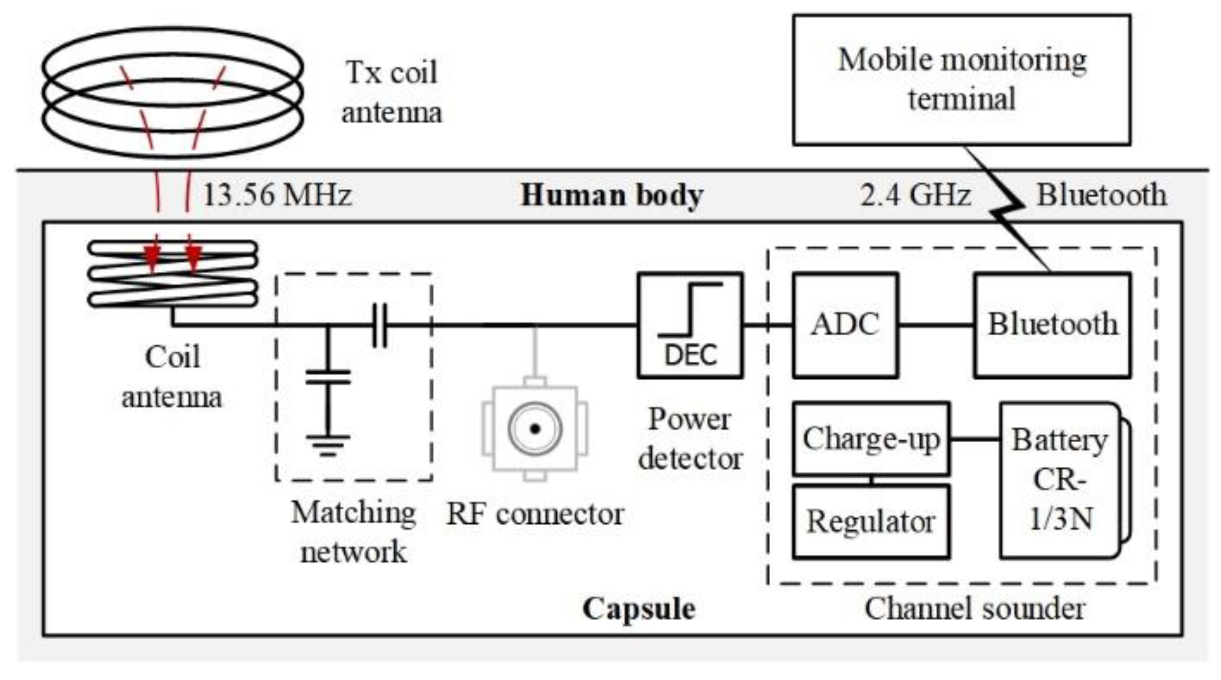
2.1. Designing a Channel Sounder Using 13.56 MHz

Figure 1 presents the structure of the channel sounder proposed in this study. The power detector measures the power level at the antenna output. Subsequently, the measured power is digitized by an analog-to-digital (ADC) converter, which is included in the Bluetooth module. The Bluetooth module modulates the digitized power and transmits it wirelessly to the outside of the human body. Finally, the measured power is received at the mobile monitoring terminal, such as a smartphone or tablet computer. The battery shown in Figure 1 supplies the power required to operate the power detector and Bluetooth module.
In this study, the channel measurement was performed at 13.56 MHz using a channel sounder. As shown in Figure 1, the channel sounder consists of a coil antenna. The coil antenna receives a test signal that is transmitted from outside the human body for channel measurements. The matching network is located between the coil antenna and the power detector to reduce the signal loss caused by impedance mismatch. Considering the limited space of the capsule-type receiver, the matching network consists of capacitors instead of inductors, which requires a larger dimension in the low-frequency band.

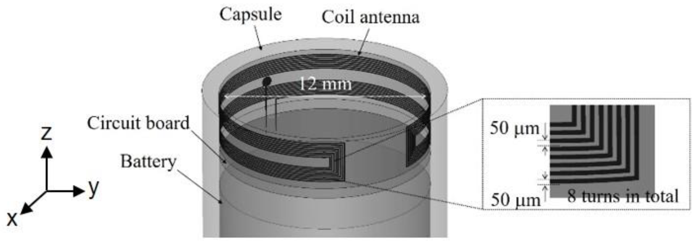
2.2. Design of a 13.56 MHz Coil Antenna

A coil antenna was designed to measure the out-body to in-body channel at 13.56 MHz. The coil antenna was inserted into a small-sized channel sounder to be placed inside the human body for channel measurements. Therefore, it was crucial that the coil antenna was small to be easily integrated into the channel sounder. We used the proposed 13.56 MHz coil antenna which could be inserted into a capsule-type channel sounder.
Figure 2 presents the structure of the proposed coil antenna. It consists of a strip line with eight turns. A strip line was formed on a flexible printed circuit board (FPCB). As shown in Figure 2, the FPCB ensured that the coil antenna could be bent into a round shape. Consequently, the coil antenna could be installed on the vertical wall inside the capsule-type channel sounder. Such an antenna structure is advantageous because the coil antenna occupies less space inside the channel sounder compared to other types of antennas. Therefore, it is easy to integrate the antenna into a channel sounder. However, it has a low operating frequency (13.56 MHz).
Another advantage of the proposed antenna is that the antenna radiation is not significantly affected by the auxiliary components inside the channel sounder. As shown in Figure 2, the auxiliary circuits and the battery are located below the 13.56 MHz antenna, and these components can obstruct the radiation from the coil antenna. However, vertical installation reduces the effects of the components on the radiation pattern. Figure 3 shows the radiation pattern simulated using the proposed antenna structure shown in Figure 2. The antenna gains are shown on the xy and xz planes. The antenna gains are relatively small. Such small gains are inevitable because the 13.56 MHz coil antenna has a compact size that is much smaller than the wavelength at 13.56 MHz. The radiation pattern of the coil antenna is similar to an isotropic pattern on the xy-plane, whereas it slightly deviates from an isotropic pattern on the xz-plane. The simulation results indicate that the antenna radiation is not significantly affected by the auxiliary components. The vertical installation of the coil antenna, as shown in Figure 2, separates the coil antenna from the other components by several millimeters. Hence, the effect of other components on the radiation pattern is reduced, enabling the antenna to have a radiation pattern close to the isotropic pattern.

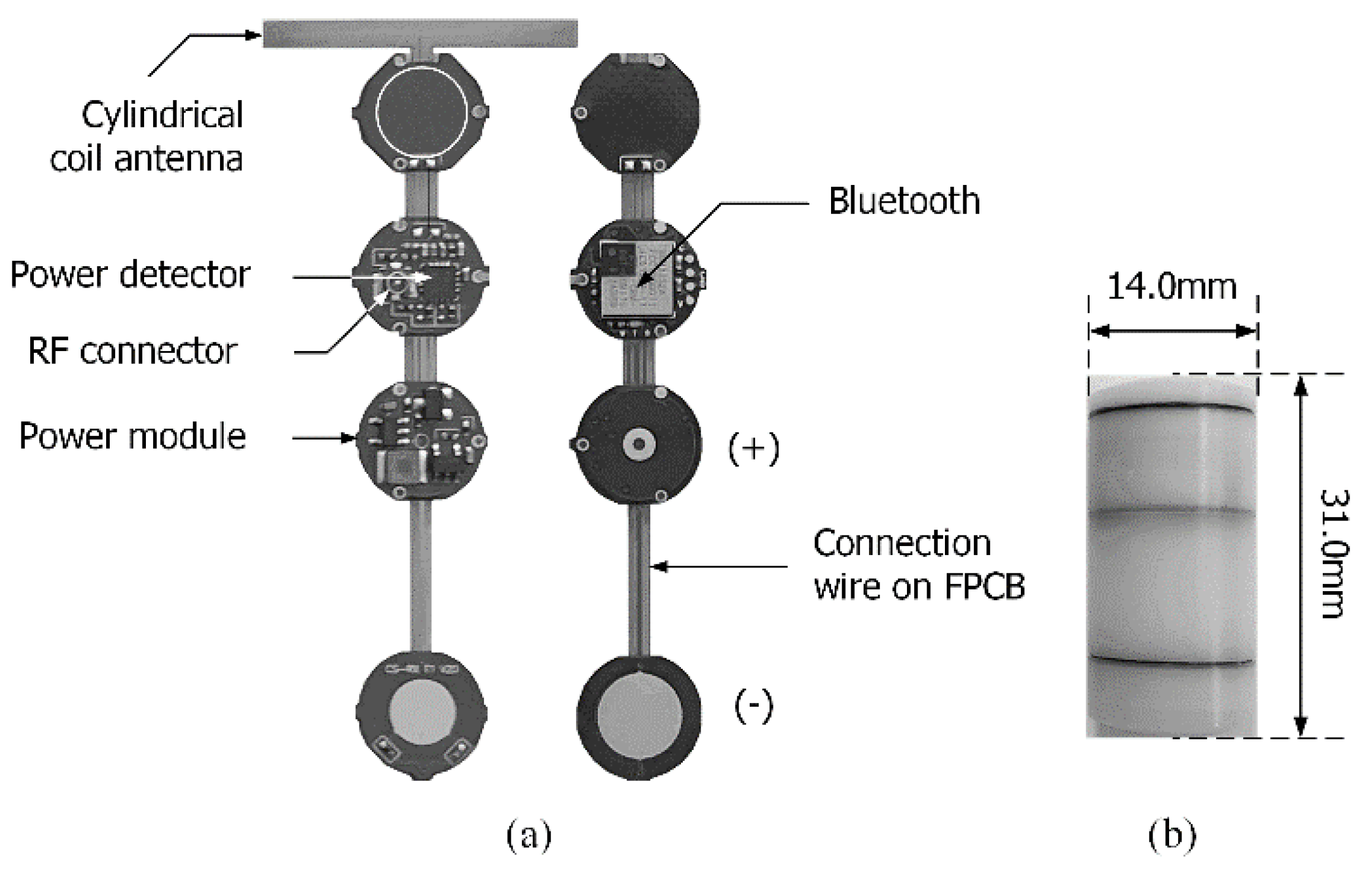
2.3. Fabrication of a Capsule-Type Channel Sounder

Figure 4 demonstrates the capsule-type channel sounder fabricated to measure the out-body to in-body channel at 13.56 MHz. As shown in Figure 4a, each component shown in Figure 1 was attached to the three circular PCBs. Circular PCBs were connected to each other through wires on the FPCBs. The components were inserted into the cylinder body, as shown in Figure 4b. The cylinder body had dimensions similar to those of a commercial capsule endoscope [8,9]. The cylinder body was constructed using polyacetal material. It had a cover on the top and bottom sides to seal the cylinder body and the components inside. The power detector and Bluetooth module were implemented using commercial chips: AD5513 for the power detector and BGM11S for the Bluetooth module [10,11]. The RF connector, as shown in Figure 4, was used to test the power detector. As shown in Figure 1, an RF connector was inserted between the matching network and the power detector. After removing the matching network, an RF signal was applied to the power detector through the RF connector. The power detector then measured the power level, and the measured power was wirelessly transmitted through the Bluetooth module. Monitoring the power level enabled us to model a linear equation between the input power and the output voltage of the power detector, as described in the following section. As shown in Figure 4, the power module provided the power to operate the channel sounder. The power module had an output voltage of 3.0 V. The consumption power of the channel sounder was 65 mW. The battery provided consumption power continuously for about half an hour.

3. Results

3.1. Measurement of Channel Sounder Performance

Prior to measuring the out-body to in-body channel, the coil antenna and power detector composing the channel sounder were measured.

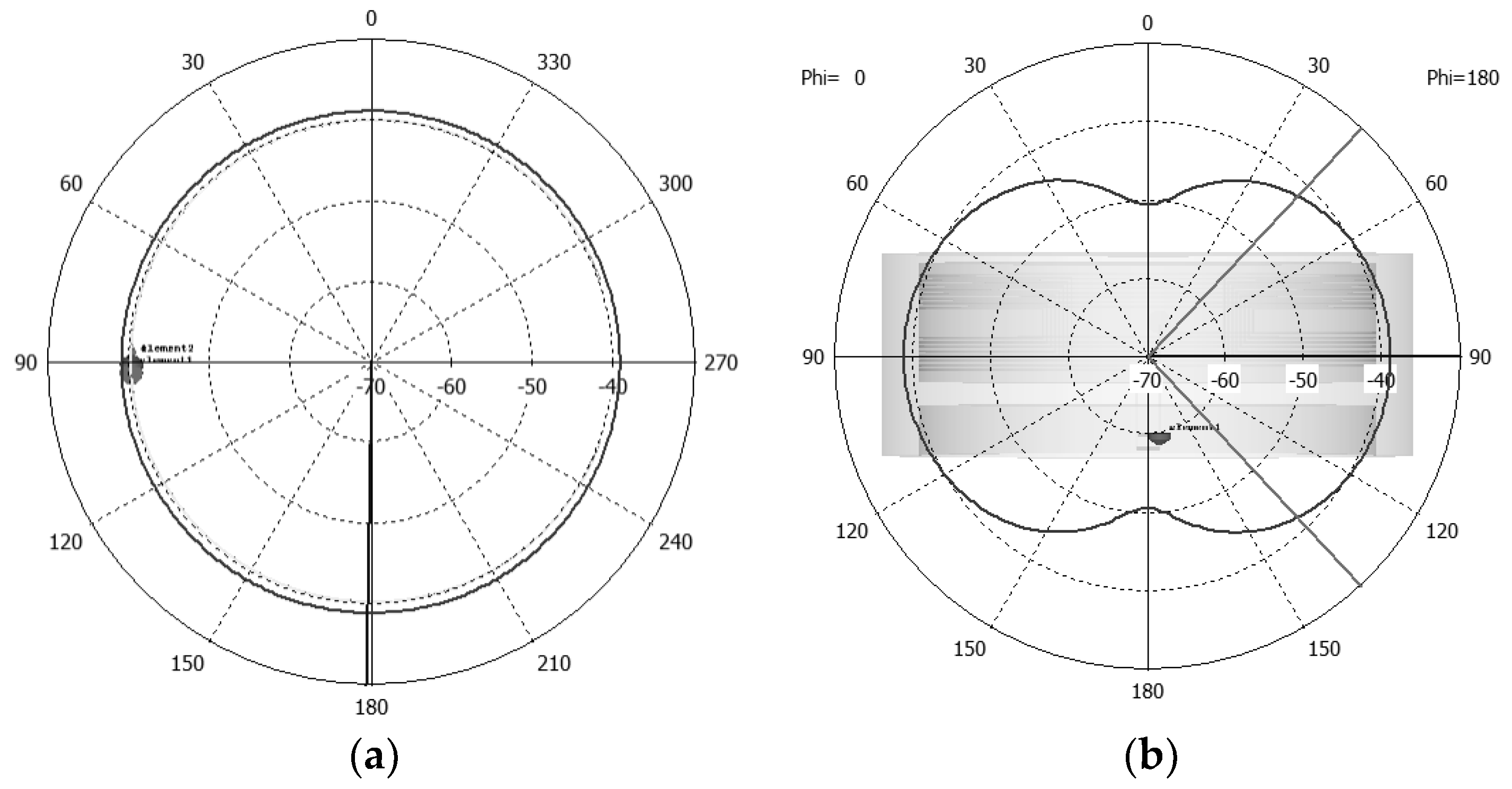
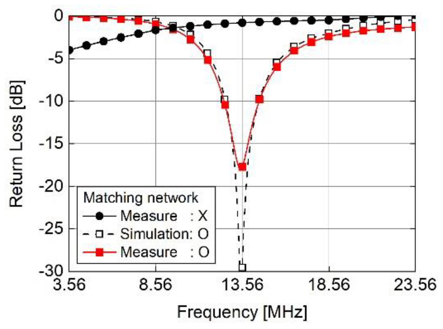
3.1.1. 13.56 MHz Coil Antenna

Figure 5 shows the return loss measured at the input of the 13.56 MHz coil antenna. Prior to the impedance measurement, the matching network, as shown in Figure 1, was tuned to match the antenna input to 50 Ω. As shown in Figure 5, the tuned matching network improved the return loss and reduced the loss occurring at the antenna input. Figure 5 also shows the return loss measured using the tuned matching network. Furthermore, it shows the simulated return loss. To obtain the simulated return loss, the return loss at the 13.56 MHz coil antenna was obtained from a numerical electromagnetic simulation for the antenna shown in Figure 2. CST Studio Suite was used for numerical simulations. The simulated return loss was imported to the ADS circuit simulator to simulate the return loss with the matching network implemented after the 13.56 MHz coil antenna. As shown in Figure 5, a similarity was observed between the measured and simulated return losses. The 13.56 MHz coil antenna had a bandwidth of approximately 2.5 MHz.

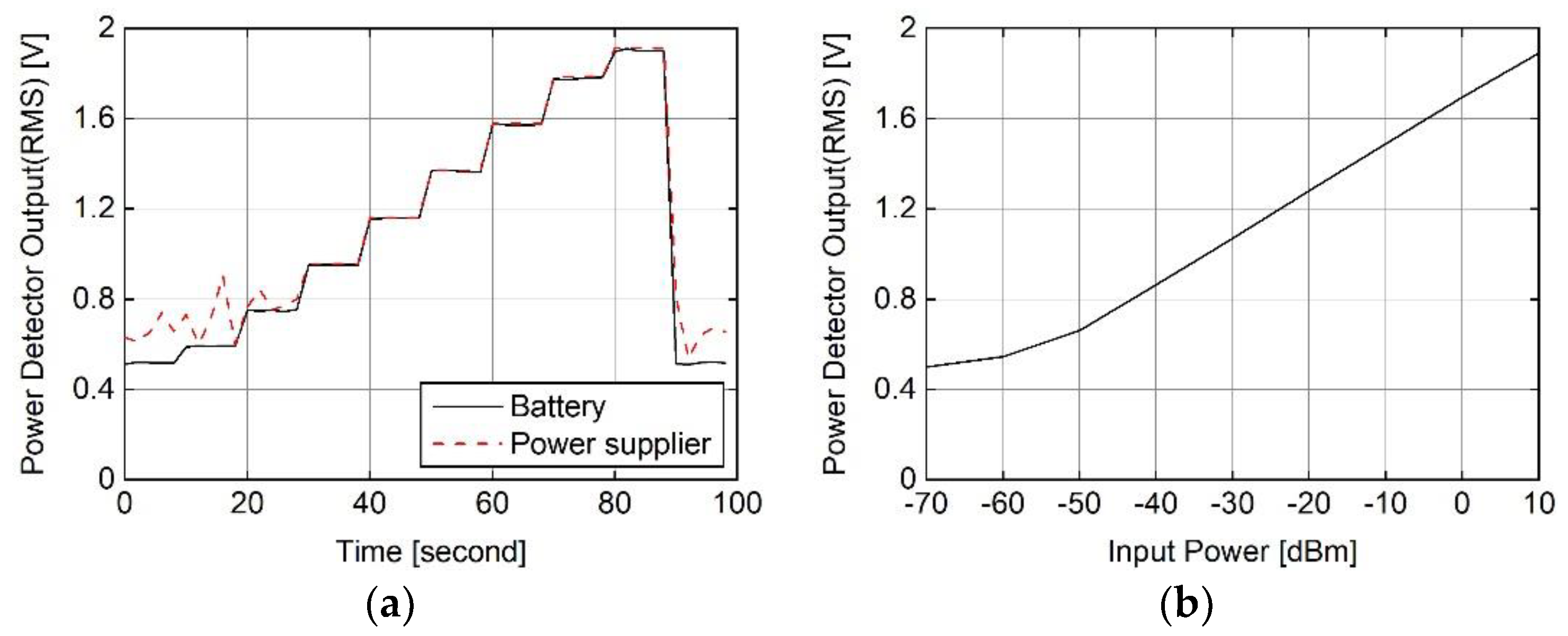
3.1.2. Power Detector

The performance of the power detector was measured by wirelessly receiving the measured power at the power detector by inputting the known power to its input. The measured power is expressed as voltage, which is proportional to the input power. For ease of measurement, the input power of the power detector was gradually increased with time. The input power was increased from −70 to 10 dBm with a 10 dB step, maintaining a constant power for 10 s at each step.
Figure 6a shows the measured power that was wirelessly transmitted from the Bluetooth module. For comparison, the power detector was powered by a battery and power supplier. The power supplier was operated with 220 V of grounded power. When the power detector was powered by the battery, the detector output increased linearly with an increase in the input power above −50 dBm. However, when the detector was powered by the power supplier, the detector output fluctuated at a low input power. This fluctuation was caused by the electromagnetic interference: the power supplier generated a conducted interference signal that fluctuated the power detector output, particularly when the input power was so low that the output voltage was also low. For channel measurements using the channel sounder, all components, including the power detector, were powered by a battery. Therefore, the fluctuation in the power detector output did not affect the overall performance of the channel sounder.
Figure 6b shows the relationship between the input and the output power of the power detector, and Table 1 summarizes the parameters to model the input and output relation. The parameters are related to the proportional property between the output voltage, V O U T , and the input power of the power detector.
V O U T = S L O G × P I N P I N T E R
where S L O G represents the logarithmic slope, which is the change in output voltage divided by the change in input power, P I N . The slope is expressed in volts per decibel (V/dB) [10]. When the input power was significantly low, the detector output had a constant voltage of approximately 0.5 V, as shown in Figure 6. The logarithmic intercept point, P I N T E R , represents an ideal input power that results in a 0 V output, assuming that the detector output is not saturated. Furthermore, the sensitivity level represents the minimum power level that can be detected by a power detector. The parameters in Table 1 were used to calculate the receiving power at the 13.56 MHz coil antenna. A linear equation was constructed using the values in Table 1 to represent the relationship between the detector output in voltage and the detector input in dBm. As shown in Figure 1, the coil antenna output was connected to the detector input; therefore, the detector input power was equal to the output power of the 13.56 MHz coil antenna.

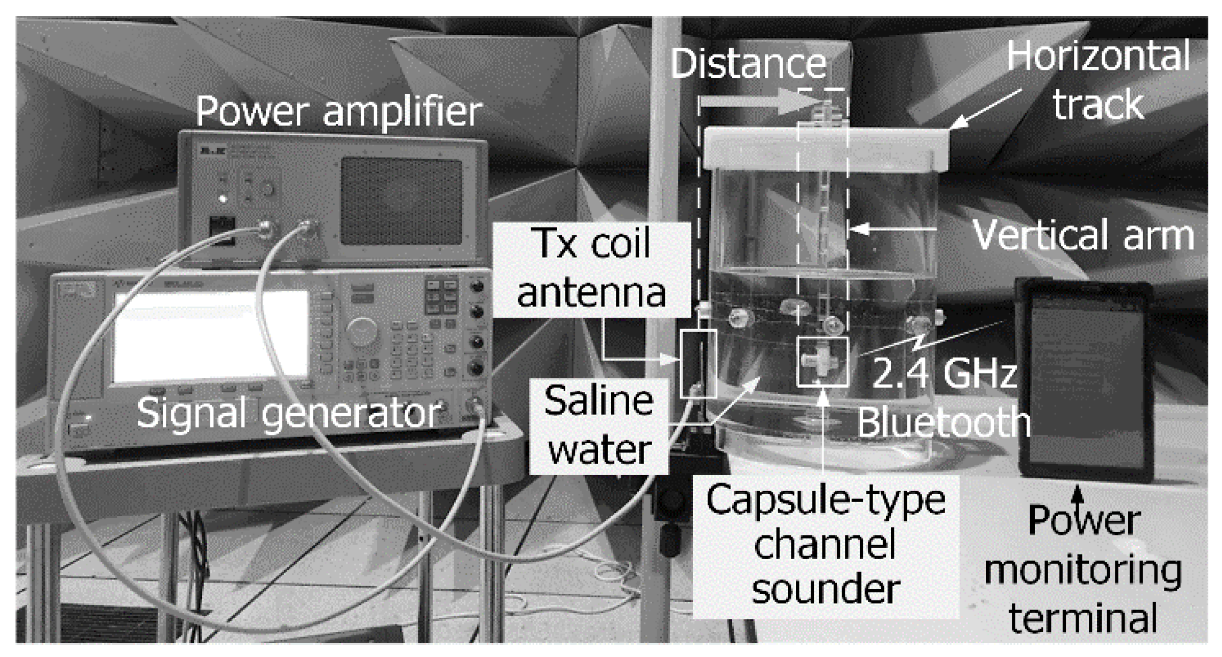
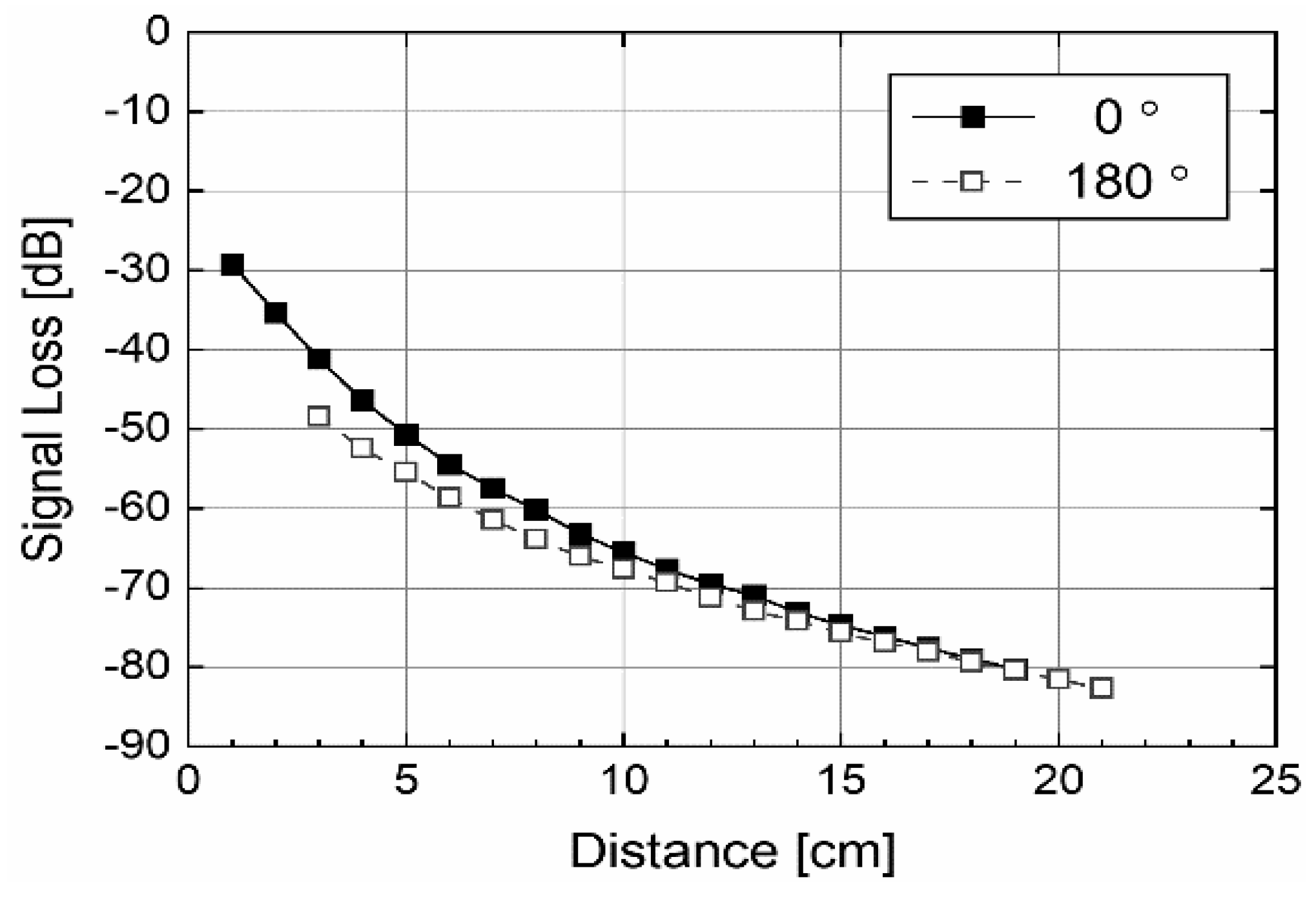
3.2. Measurement of the Out-Body to In-Body Channel Using a Capsule-Type Sounder

The out-body to in-body channel was measured using the fabricated channel sounder. Figure 7 demonstrates the setup used to measure the signal loss in the channel. The water tank consisted of saline water. For the measurement in this study, the out-body to in-body channel was mimicked using saline water, as described in [12,13]. Saline water has a conductivity similar to that of a real human body. Hence, the signal loss can be measured under conditions similar to those experienced by an implantable device located inside the human body. As shown in Figure 7, the capsule was placed inside saline water using a vertical arm that held the capsule-type channel sounder at its tip. Using the horizontal track, the vertical arm could be moved in the horizontal direction to adjust the location of the channel sounder. The signal generator, as shown in Figure 7, generated a 13.56 MHz continuous wave (CW) signal, and the generated signal was transmitted to the transmitting coil antenna. The transmitting coil antenna was attached to the surface of the water tank. The transmitted signal generated a magnetic field at 13.56 MHz. To increase the intensity of the magnetic field, the power amplifier amplified the 13.56 MHz signal before being transmitted to the transmitted signal generator.
The transmitting coil antenna, as shown in Figure 7, generated a magnetic field at 13.56 MHz outside the mimicking channel; that is, saline water. The generated field was transmitted through the mimicking channel. Subsequently, the channel sounder received the transmitted signal inside the mimicking channel using the 13.56 MHz coil antenna. The channel sounder wirelessly transmitted the output voltage of the power detector through the Bluetooth module. Outside the mimicking channel, the mobile monitoring terminal received the output voltage and converted it into the power level at the 13.56 MHz coil antenna using (1), which represents the relationship between the detector output and input as previously described. Finally, the signal loss of the out-body to in-body channel was calculated by subtracting the measured output power at the 13.56 MHz coil antenna from the input power at the transmitting coil antenna.
Figure 8 shows the signal loss calculated for the out-body to in-body channel. The signal loss was measured by changing the distance between the transmitting coil antenna and the capsule-type channel sounder. For this, the vertical arm holding the channel sounder was moved along the horizontal track, as shown in Figure 7. As shown in Figure 8, the signal loss increased exponentially with increasing distance.
An implantable device rotates randomly inside the human body. Therefore, the 13.56 MHz coil antenna is not aligned with the transmitting coil antenna outside the human body. Considering random rotations, the signal loss was measured in the same way after rotating the capsule-type channel sounder by 180° on the horizontal plane. The horizontal rotation was selected because it maximizes the distance of the coil antenna inside the capsule-type channel sounder from the transmitting coil antenna, which corresponds to the worst case for the out-body to in-body channel. As shown in Figure 8, the horizontal rotation slightly increased the signal loss, but the increase was less than 10 dB. Such a small increase was caused because the out-body to in-body channel used a low frequency of 13.56 MHz. The coil antenna inside the capsule-type channel sounder moved by the horizontal rotation, but the movement distance was much smaller than the wavelength, thus affecting the signal loss less.
As shown in Figure 8, the signal losses were missing at distances of 1 and 2 cm because the 13.56 MHz coil antenna was located on the left side of the channel sounder, as shown in Figure 7. Consequently, the smallest distance between the 13.56 MHz coil antenna and the transmitting antenna was 3 cm. The signal loss was measured with a horizontal rotation of 90°. The measured signal loss was between that at rotation angles of 0° and 180°.

4. Conclusions

This study proposed a capsule-type channel sounder. The channel sounder could measure the signal loss of the out-body to in-body channel used for an implantable device to transmit data outside the human body. The proposed channel sounder measured the receiving power inside the human body and then wirelessly transmitted the measured power outside the human body. A wire connection was not required for the channel measurement. Therefore, the out-body to in-body channel could be measured without any interference between the channel transmitter and the receiver.
This study showed that the proposed channel sounder could be implemented inside a swallowable-type capsule. The proposed sounder, however, can be implemented in other types of implantable devices, such as cardiac pacemakers, neurostimulators and cochlear implants. Such channel sounders enable us to measure the properties of the body channel, and the measured channel properties can be used to design each device or enhance its performance. In addition, wireless power transmission can be designed for implantable devices using measured channel properties.

Author Contributions

Conceptualization, J.J.; validation, S.S. and M.L.; investigation, J.J. and S.S.; data curation, J.J. and M.L.; writing—original draft preparation, J.J.; writing—review and editing, Y.T.K.; supervision, M.L. and Y.T.K. All authors have read and agreed to the published version of the manuscript.

Funding

This research was supported by the Healthcare AI Convergence R&D Program through the National IT Industry Promotion Agency of Korea (NIPA) funded by the Ministry of Science and ICT (No. S1601-20-1041) and the Basic Science Research Program (No. 2018R1A6A1A 030 15496) through the NRF of Korea and the National Natural Science Foundation of China (62001186).

Conflicts of Interest

The authors declare no conflict of interest.

References

  1. Das, R.; Moradi, F.; Heidari, H. Biointegrated and wirelessly powered implantable brain devices: A review. IEEE Trans. Biomed. Circuits Syst. 2020, 14, 343–358. [Google Scholar] [CrossRef] [PubMed] [Green Version]
  2. Streckenbach, S.; Lai, Y.; Bas, H.; Crowley, J.; Salzsieder, H.; Mela, T.; Dalia, A.A. Starting an Anesthesia-based perioperative device management service: A practical guide to training anesthesiologists. J. Cardiothorac. Vasc. Anesth. 2021, 35, 1006–1017. [Google Scholar] [CrossRef] [PubMed]
  3. Li, Y.; Li, N.; De Oliveira, N.; Wang, S. Implantable bioelectronics toward long-term stability and sustainability. Matter 2021, 4, 1125–1141. [Google Scholar] [CrossRef]
  4. Astrin, A. IEEE Standard for Local and metropolitan area networks part 15.6: Wireless Body Area Networks. IEEE Std 802.15. 2012, 6. [Google Scholar] [CrossRef]
  5. Hayami, H.; Ishii, Y.; Sasagawa, K.; Noda, T.; Tokuda, T.; Ohta, J. Body channel digital pulse transmission for biometric measurement by fully implantable CMOS image sensor. In Proceedings of the 2014 IEEE International Meeting for Future of Electron Devices, Kansai (IMFEDK), Kyoto, Japan, 19–20 June 2014; IEEE: Piscataway, NJ, USA, 2014; pp. 1–2. [Google Scholar]
  6. Vasić, Ž.L.; Cifrek, M.; Gao, Y.; Du, M. Preliminary Characterization of Capacitive Intrabody Communication Channel under Implantable-Like Conditions. In Proceedings of the 2020 IEEE International Instrumentation and Measurement Technology Conference (I2MTC), Dubrovnik, Croatia, 25–28 May 2020; IEEE: Piscataway, NJ, USA, 2020; pp. 1–5. [Google Scholar]
  7. Yordanov, V.A.; Bentum, M.J. Modulated scatterer technique probe for intra-body RF channel measurements. In Proceedings of the 8th European Conference on Antennas and Propagation (EuCAP 2014), The Hague, The Netherlands, 6–11 April 2014; IEEE: Piscataway, NJ, USA, 2014; pp. 1757–1759. [Google Scholar]
  8. Intromedic ‘Microcam’ in Online. Available online: https://www.intromedic.com:549/eng/item/item_010100_view.asp?search_kind=&gotopage=1&no=32 (accessed on 10 October 2021).
  9. Olympus ‘PillCam’ in Online. Available online: https://medical.olympusamerica.com/procedure/capsule-endoscopy (accessed on 10 October 2021).
  10. Analog Devices, ADL5513. Available online: https://www.analog.com/en/products/adl5513 (accessed on 10 October 2021).
  11. Slicon Labs, BGM11S. Available online: https://www.silabs.com/documents/public/data-sheets/bgm11s-datasheet (accessed on 10 October 2021).
  12. Hyoung, C.H.; Hwang, J.H.; Kang, S.W.; Park, S.O.; Kim, Y.T. A feasibility study on the adoption of human body communication for medical service. IEEE Trans. Circuits Syst. II Express Briefs 2015, 62, 169–173. [Google Scholar] [CrossRef]
  13. Park, M.J.; Kang, T.; Lim, I.G.; Oh, K.I.; Kim, S.E.; Lee, J.J.; Park, H.I. Low-power, high data-rate digital capsule endoscopy using human body communication. Appl. Sci. 2018, 8, 1414. [Google Scholar] [CrossRef] [Green Version]
Figure 1. Structure of the channel sounder for the measurement of 13.56 MHz channel.
Electronics 10 02895 g001
Figure 2. Structure of the proposed 13.56 MHz coil antenna.
Electronics 10 02895 g002
Figure 3. Simulated antenna gain at 13.56 MHz on the (a) xy-plane and (b) xz-plane of Figure 2.
Electronics 10 02895 g003
Figure 4. Fabricated capsule-type channel sounder: (a) sounder components and PCB connection and (b) sounder exterior including all components.
Electronics 10 02895 g004
Figure 5. Measured, simulated and measured return losses for 13.56 MHz coil antenna.
Electronics 10 02895 g005
Figure 6. (a) Measured output voltages of the power detector for increasing power and (b) relationship between the detector input and output.
Electronics 10 02895 g006
Figure 7. Measurement setup for the out-body to in-body channel.
Electronics 10 02895 g007
Figure 8. Measurement of the signal loss for the out-body to in-body channel.
Electronics 10 02895 g008
Table 1. Performances of the power detector.
Performance ItemUnitMeasured Value
SlopeV/dB20.70
Intercept pointdBm−81.87
SensitivitydBm−72.00
Publisher’s Note: MDPI stays neutral with regard to jurisdictional claims in published maps and institutional affiliations.

