1. Introduction
Because of the rapid development of sensor components, information technology, and wireless network technology in recent years, the development of industrial network applications has been accelerated. The related applications include, but are not limited to, smart vehicles, smart security, smart logistics, smart medical system, smart entertainment, smart energy, and smart buildings. The Internet of Things (IoT), which is considered to be the central topic in the next wave of industrial revolution and development of information and communication technology industry in the future, offers huge business opportunities and has become a key field for manufacturers to compete.
Recently, many information technologies (e.g., IoT, big data, and cloud computing) have been introduced into traditional industries and have introduced a significant effect on the development of industry 4.0. A cyber-physical system (CPS) [
1] is an integrated system that combines the field of computer computing with sensors, actuators, and computer computing, and these are widely adopted in factories. The implementation of IoT devices in the factory enables data collection during the manufacturing process. Along with a growing body of evidence that shows the performance of the physical network manufacturing system, and understands the supporting data-driven decision-making process, there is a large amount of relevant literature by scholars that investigates [
2] and analyzes networks of physical, sustainable, intelligent manufacturing systems and sensing technology; and integrated with the sustainable, intelligent manufacturing point of view, we can see that today’s smart and sensing technology becomes very important. To fully fathom the challenges and opportunities ahead, we must adopt a holistic view of CPSs that includes self-adaptation, autonomy, efficiency, functionality, reliability, safety, scalability, and usability. In the CPS adaptive literature section, scholars discuss the techniques needed to build a common CPS architecture that provides efficient adaptive features. Based on the literature review of adaptive technology in CPSs by scholars [
3,
4], these studies discuss the technologies needed to build a common CPS architecture, and considers that effective mechanisms must be developed to provide self-monitoring capability for CPS subsystems to prevent or correct abnormal behavior in operation and adapt to respond to the occurrence of faults and errors. As well as changing environmental conditions or the state of internal CPSs, the architecture must provide efficient adaptive features. In addition to exploring adaptability, cloud computing and big-data technologies have also emerged in the scientific community in recent years as key enabling technologies to address the current needs of CPSs, the value creation utilizing cloud-based CPS in robotic mobile fulfillment system had been addressed [
5]. The large-scale CPS real-time monitoring platform based on big data technology is designed to perform real-time analysis with the goal of monitoring industrial machines in a real work environment. This was verified by implementing the proposed solution on a real industrial-use case involving multiple industrial presses [
6].
The real physical phenomena are converted into digital values so that a virtual digital system can communicate with the physical world. For example, in the intelligent factory of Siemens in Germany Amberg, 75% of the workload can be replaced by machines, and the factory has a yield of almost 100% [
7]. The research and application of task allocation in a multirobot system [
8], which is an intelligent factory, has been developed for many years, but the current multirobot task-assignment mechanism can not easy to implemented in real robot systems directly. The present study explicates the problem of heterogeneous multirobot cooperative-task assignment. A distributed auction algorithm was designed to classify the different abilities of robots using atomic capabilities. According to the distance between the robot and target task, and the matching degree between the robot and task, a task-assignment problem model was established to solve the heterogeneous multitask problem; namely a robot collaborative-task assignment system. The simulation results show that the model is correct and the algorithm is effective. The current research provides a blueprint from existing manufacturing systems to smart factory. An empirical study was conducted at a leading thin-film-transistor liquid-crystal display (TFT-LCD) company [
9], which proposed a simulation-based dynamic scheduling and dispatching model for TFT-LCD array manufacturing. The results demonstrated that the capacity loss of a bottleneck workstation and delivery tardiness could be significantly improved by the proposed hybrid genetic algorithm. This contribution provided an insight into how this objective can be achieved by utilizing software-defined networking for the specific use of the smart factory web [
10]. To address the heterogeneous and changing demands of the users, the factory has made flexible not only its production assets but also its network in terms of management and configuration. After deep-learning-based quality control, the satisfactory products are forwarded to the production stages, and the unsatisfactory products are separated [
11]. In the present research, a visual quality-control automation application is proposed using a camera installed over the assembly line in a smart-factory model. We used the cloud-coupler and plug-and-work techniques to create a new factory or retrofit an existing one that is available in the smart factory web to share capability information toward a new marketplace for manufacturing [
12]. In the present study, we not only reduce the technical efforts but also the use of standards to define the interfaces. Cloud–fog computing network architecture can be efficiently used to store, analyze, and utilize the accumulated data in smart factories [
13]. We built and evaluated the system model, and developed a testbed based on the proposed architecture. As a result, the cloud developed in the open stack can be used for smart-factory operations, analyze various types of data, and check the status of real-time processing through a dashboard. These processes create the most suitable structure for a smart-factory environment that requires real-time performance. Some problems that industrial big-data systems meet in a smart factory are discussed [
14]. The design concerns of the industrial big-data-based system are abstracted from the product life-cycle perspective. The design concerns focus on the requirements from consumers, system builders, and other stakeholders in the smart factory.
Owing to the development of intelligence technology, the production model is oriented from previous mass production to customized demand, and the production line must be highly adaptable to the customized demand. Many different innovative architectural designs for Industry 4.0 are continuously proposed [
15,
16,
17]. In addition, a more popular need is required to upgrade the existing industry and improve its automation. Generally, small-scale manufacturers often cannot sufficiently invest to build advanced intelligent production, such as in semiconductor factories and related industries. Often, they can only gradually upgrade their existing machinery. In recent years, production lines have relied more and more on flexible or smart work cells, especially within the context of Industry 4.0. Although many people want to build a smart factory, upgrading the degree of automation of existing factories is a more important requirement. Therefore, machine-to-machine (M2M) and Internet of Things (IoT) technologies have been continuously introduced into the industry to analyze production and diagnose problems in order to improve the factory’s automation. Currently, scholars are discussing a pluggable software Orchestrator [
18], which can automatically extract instructions from a given input, set the factory process accordingly, and execute production by itself to realize a dynamic resource arrangement. The automation of a robot control system based on an automatic programming environment minimizes user rework and analysis time when there is a frequent need to redistribute the robot task through robot self-observational learning, independent reprogramming, or—through the integration of the M&S environment—maintain and promote model reuse, and to provide an automatic model-generation function to obtain the best solutions [
19,
20]. At present, even internal personnel training of enterprises has introduced intelligent learning [
21]. CNN neural networks with SVM classifiers can extract and share expert knowledge according to film materials, effectively improve the learning process of employees in manufacturing companies, and shorten the time cost of personnel training. In this research, the IAPLCS was successfully developed and applied to the actual automatic production. It will become more convenient to edit and monitor the control process by using the GCS. Users can also get equipment information, including the grain rate, intelligent sensor data, real-time production line monitoring, etc. This will help narrow the gap between research and practice, and allow users to apply the system flexibly, which will helpful to implement different smart manufacturing strategies.
Therefore, the current research aims to develop a general automation-equipment control system with communication integration and a graphic control interface that can adapt to the production-line process in order to complete different production requirements.
2. Materials and Methods
Smart production-line conceptual diagram in this IAPLCS is shown in
Figure 1, automatically processes, analyzes, communicates, and feeds back constructive information in real time to the user interface when the embedded sensors send messages to the data server through the network. This system represents an integration of the machine-to-machine and machine-to-system structures, and it effectively manages the relationships of automation equipment. In this system, production processes can be selected using mobile phones or desktops. Moreover, the current status of the production line is displayed on the user interface in this system. When a fault or event occurs, the alarm is triggered, and a notification is then sent via email or SMS to relevant personnel.
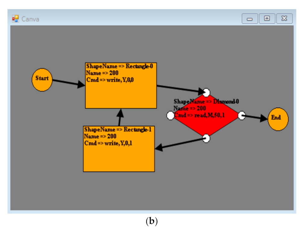
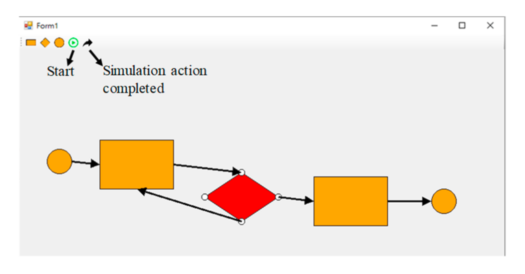
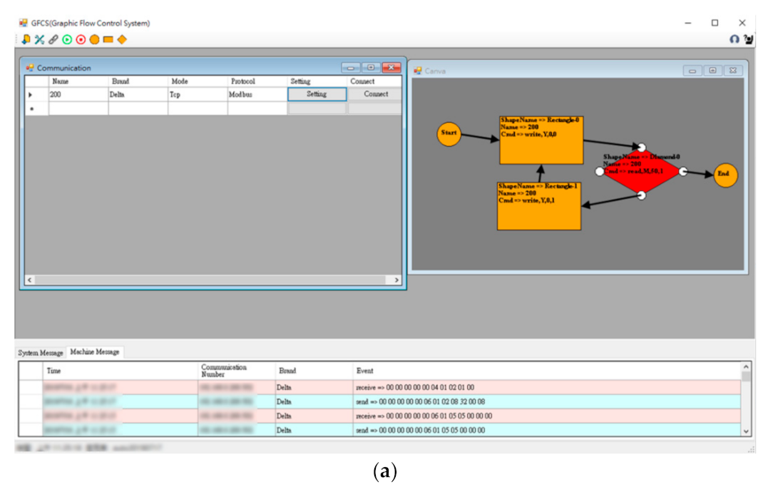
A GCS for automation equipment with communication integration was developed to address quick changes in the production-line processes. A graphical interface is needed to package the machine communication and commands into graphics to develop and quickly change the process needs. Then, we used a simple flowchart to build the relationships of the production-line control process, as shown in
Figure 2. As shown in
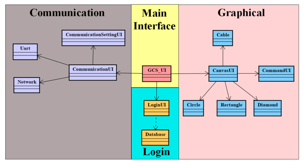
Figure 2b, there are three most commonly used functions, namely the circle responsible for the beginning and end, the rectangle responsible for the program steps, and the diamond responsible for decision-making. In the flowchart example, Rectangle-0 executes the action of writing Y0 as 0 after the program flow starts. In the next step, Diamond-0 determines whether M50 is 1—if it is, it ends the program; if not, it skips to Rectangle-1 to execute writing Y0 as 1, and jumps to the rectangle to continue execution. When the process needs to be changed, a block can be dragged to the appropriate position, and a relationship can be developed to complete the modification. In the present study, an object-oriented programming method is adopted to subdivide the system into many classes to develop suitable system architecture. Therefore, this system is more convenient for maintaining or updating the system in the future. The class hierarchy proposed in this research is shown in
Figure 3. It is divided into the GCS main interface, communication area, login area, and graphical area. The composition, structure, and functions of each area are described in the next sections.
2.1. Main Interface Area
A GCS_UI class is present in the main interface, and this class represents the main control interface of this system. It is responsible for interface management and system-information display of the other small systems.
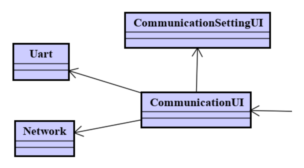
2.2. Communication Area
The communication area is responsible for all communications of the operating equipment. This area is divided into four classes: Communication UI, CommunicationSettingUI, Uart, and Network. The area is dominated by Communication_UI, which can implement the communication-setting interface (CommunicationSettingUI), and a user can setup the communication parameters required for control. Then CommunicationUI implements the corresponding communication objectives according to the input parameters and stores them in an array, which is provided to the system when the system requires.
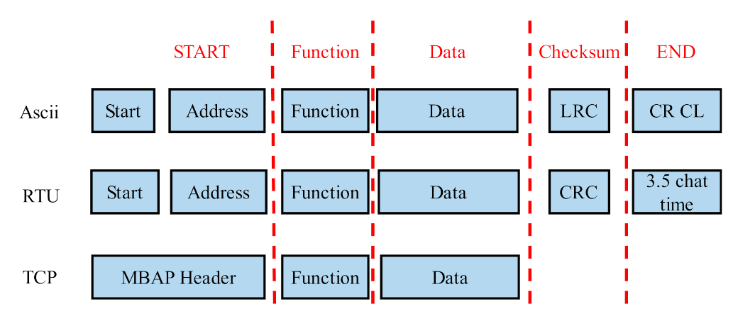
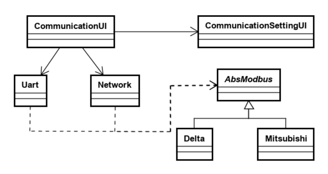
Currently, many communication methods are used in the industry. Famous factories and associations have also developed their own communication formats such as Profibus (Siemens Co., Munich, Germany), EtherCAT (Beckhoff Co., Verl, Germany), Ethernet/IP (Rockwell Automation Co., Milwaukee, WI, USA), CC-Link (CC-Link Partner Association), and Profibus (Profibus Association). However, the current research focuses on the communication of existing equipment in traditional industries, including the communication methods such as TCP, UDP, RS232, or RS485. These methods can be divided into two transmission methods: Network and Uart, which are programmed in individual classes for use. If a device with another communication protocol needs to be controlled, the system can separately add this class.
2.3. Login Area
The login area is responsible for the operation restrictions of the system, and the corresponding operation restrictions are opened via an account permission level. According to its functionality, it is divided into two classes; namely, LoginUI and Database. In LoginUI, users can enter their account and password and wait for the login button to be pressed. After the button is pressed, LoginUI creates a database object and links it to the database for account verification to create system-operation management. In addition to protecting the user accounts and passwords, a verification code and data encryption in LoginUI is necessary to avoid data leakage due to brute-force cracking and packet interception.
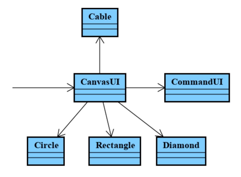
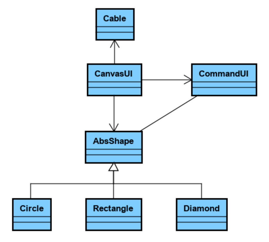
2.4. Graphical Area
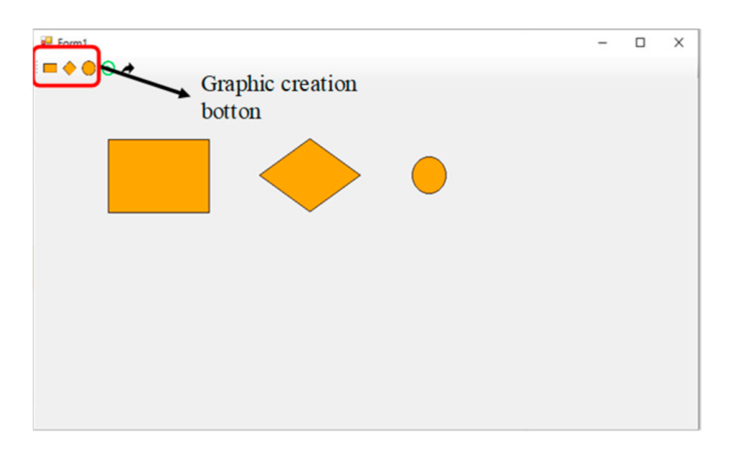
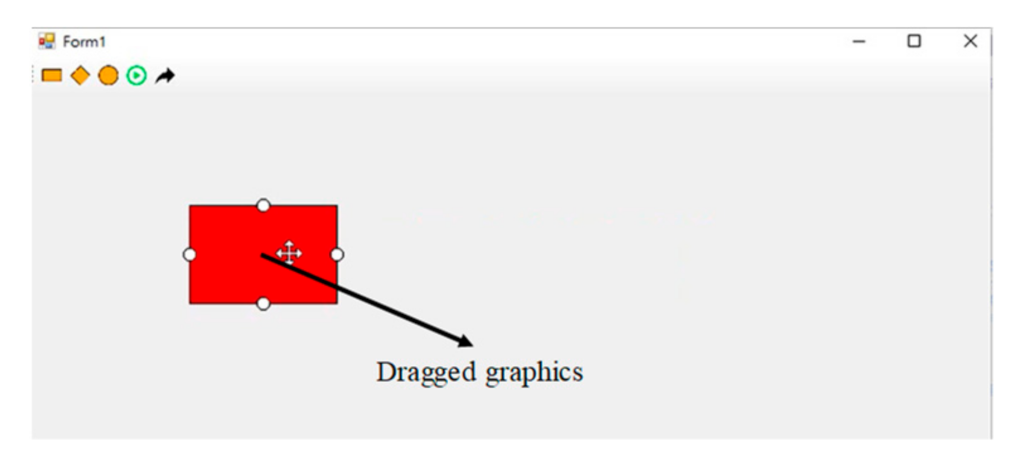
The graphical area is responsible for the sequence setting of the process and formulation of the control commands. The commands are packaged into functional blocks, and the control commands are sent according to the order of the user needs. Functionality is divided into graphical main interface (CanvasUI), command interface (CommandUI), connection line (Cable), and three functional blocks (Circle, Rectangle, and Diamond). The canvas can create different functional-block diagrams; namely, “Circle”, which is responsible for the start and end of the process, “Rectangle”, which is responsible for the output of the action commands, and “Diamond” to read and distinguish values. Using the aforementioned three function blocks, flow control can be established. The command is implemented on the function block. Users can enter the command for control on its interface and finally connect it through the cable according to the desired control order.
5. Intelligent Automatic Production-Line Control System
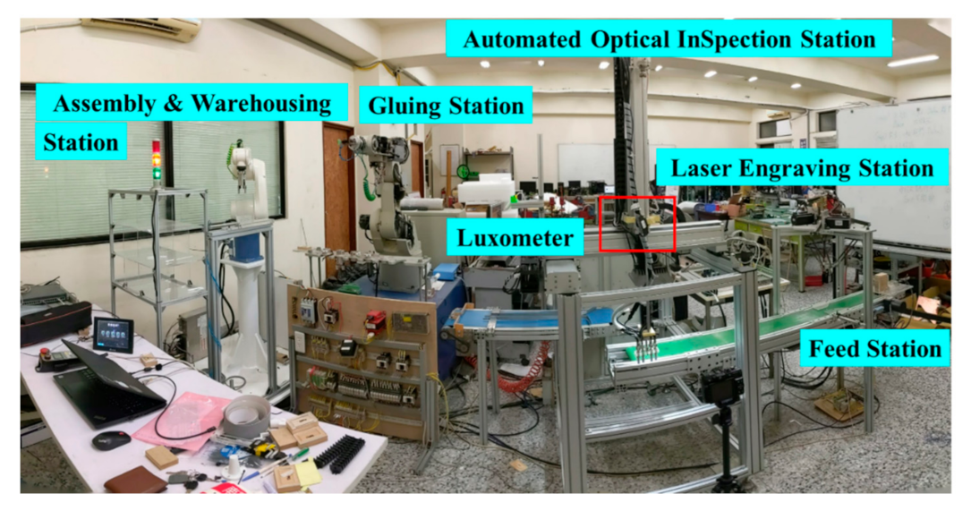
Following the trend in Industry 4.0 and smart manufacturing, this intelligent production line has been developed in our laboratory to realize communication integration, data collection, and visualization. It is made up of five equipment workstations: Feed Station, Laser-Engraving Station, Automated Optical Inspection Station, Gluing Station, and Assembly and Warehousing Station (
Figure 13). A luxometer was adopted as the IoT sensor in the redbox in
Figure 13 to ensure that the visual inspection was correct. If other sensors are needed, such as luminosity, temperature, color, pressure, speed, etc., in the same way, the sensor data will be collected and displayed in the IAPLCS.
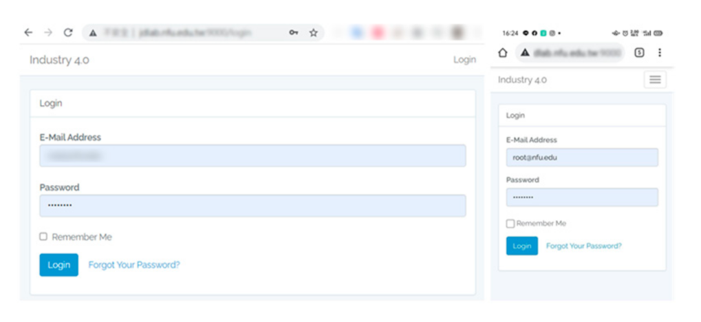
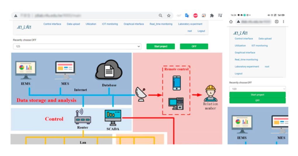
The web interface of this system was designed using Laravel Framework. For security reasons, users must sign up and be authorized before accessing this system (
Figure 14). The information about this production line is displayed on the screen according to the function options selected by the user, including data upload, control interface, utilization, IoT monitoring, and graphical interface.
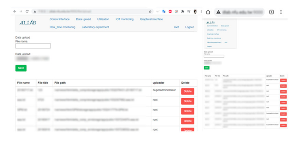
Figure 15 shows that the data-upload function facilitates either creating, editing, or deleting the filename or path of a new project script.
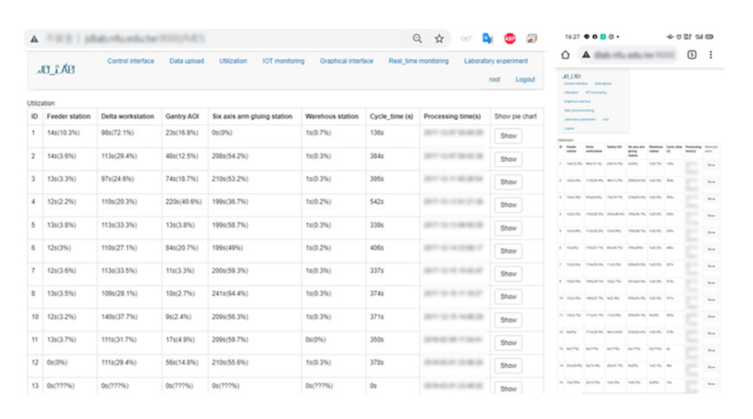
Figure 16 shows that starting or stopping the selected project is controlled by the control interface, which is used to schedule the production line or adjust the condition of the production line. To quickly improve efficiency and better understand the operation status of the entire production line, the working time of each workstation was converted into utilization rate and cycle time and recorded on the utilization-rate display interface (
Figure 17).
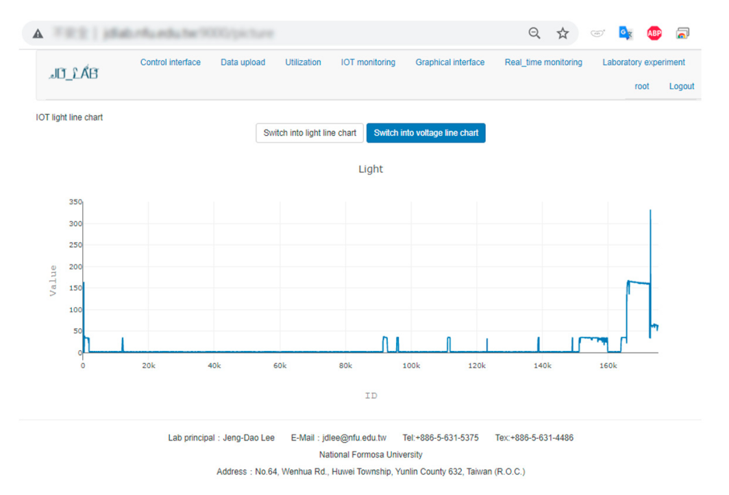
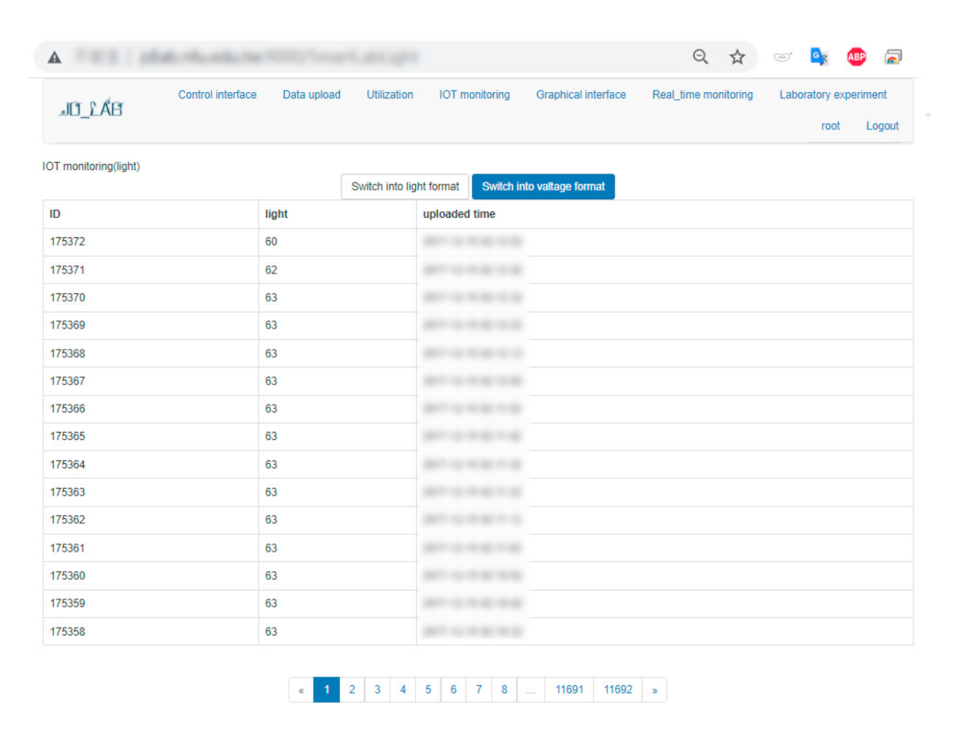
Figure 18 shows that IoT sensors are installed on site, and the data are uploaded via a Wi-Fi network and directly transferred to the database for further analysis. The IoT data are also visualized in the graphic interface for the users to receive the real-time IoT situation (
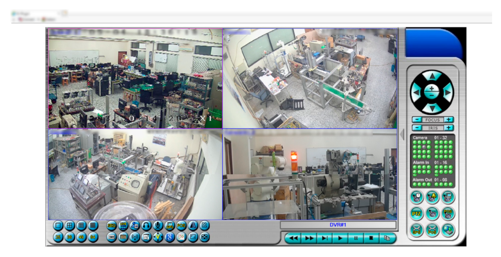
Figure 19). To track the machines’ performance across the factory floor or to solve problems promptly, the remote real-time monitoring system is well-established on the interface (
Figure 20).
6. Integration and Experiment
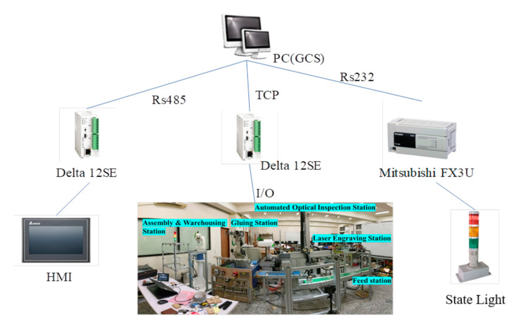
In the experiment, the automatic production line, human machine interface (HMI), and warning lights with different generally used communication methods, including RS232, RS485, and TCP, were controlled by IAPLCS.
Figure 21 shows the experimental-system architecture diagram. An individual PLC sends the command to HMI, production line, and warning light when a recommendation is received from GCS. The user only changes the GCS graphical interface process, which automatically satisfies effective changing of the production schedule.
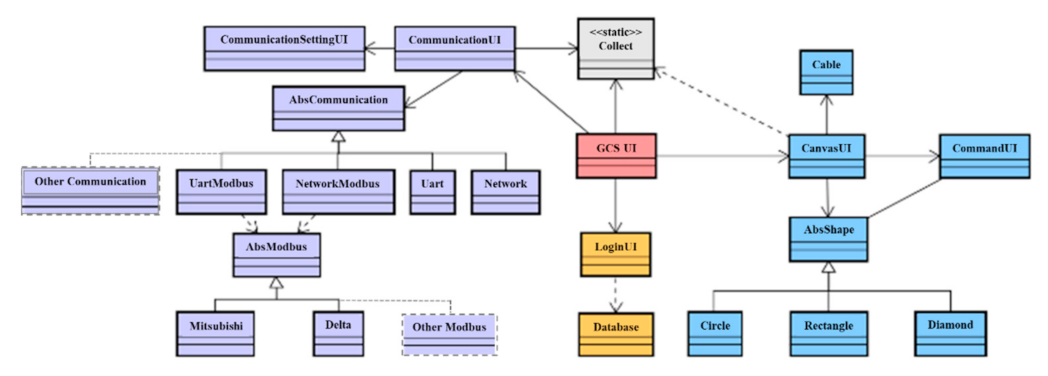
According to previous tests in the design stage, a class diagram can be reconstructed, as shown in
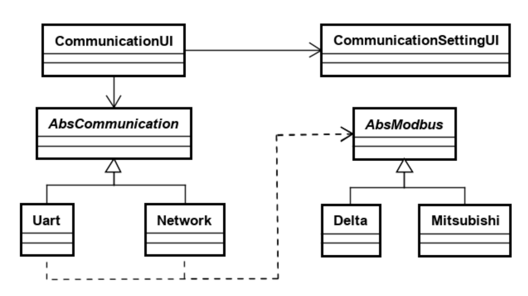
Figure 22. GCS_UI is used to control other small system interfaces. Then, the small system interfaces are used to control different classes of function. They can separate a complicated system into several structures and allow easier system maintenance or upgrading. Moreover, public static classes are added for communication between the two systems introduced earlier. Communication UI saves the established AbsCommunication in Collect and prepares it for the other systems to use. When the system operating parameters are all set, GCS_UI calls CanvasUI to start graphical control after the start button is pressed. According to the requirements of the program, the communication parameters are set by CommunicationSettingUI, and the corresponding action signals are extracted from Collect and sent to AbsCommunication for transcoding, transmission, return comparison, and other functions. AbsCommunication is composed of the following four communication methods: UartModbus, NetworkModbus, Uart, and Network. In addition, new communication methods can also be expanded, such as CC-link, Devicenet, etc. We have also built a new AbsModbus, which includes devices from two manufacturers, Mitsubishi and Delta, which are used to process Modbus-related communication protocols. Besides this, devices with Modbus communication protocol and different data addresses can also be expanded according to the architecture shown in
Figure 22.
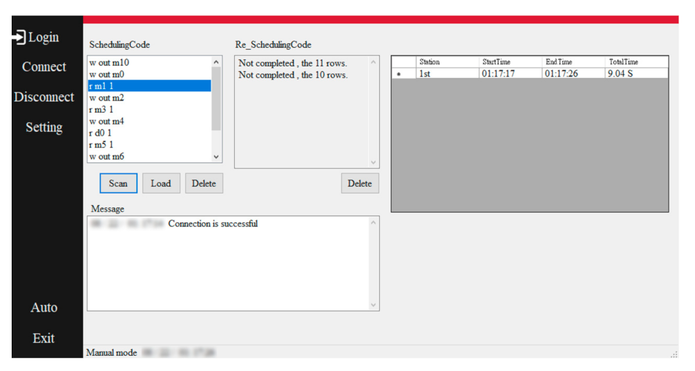
The central control program (CCP) interface is shown in
Figure 23. After CCP is opened, the user must first set some basic communication parameters, connect the device to the IP and corresponding port, and click the automatic function button after completion. CCP then automatically runs and connects to the server and PLC. After the connection is successful, it waits for the start signal from the web page. When the remote start signal is received, the subprogram is started. In the subprogram, the project schedule is downloaded from the file transfer protocol (FTP) server and loaded into the execution window. CCP reads the project command code in the execution window and converts it into Modbus TCP to control the PLC. During this process, it records each command and response time. The utilization rate can be calculated using these data and transmitted to the database.
As previously mentioned, through the web-page production, graphic control design, communication-system structure, and CCP, IAPLCS is established, and this system can be applied to the self-designed production line. The production-line layout is shown in
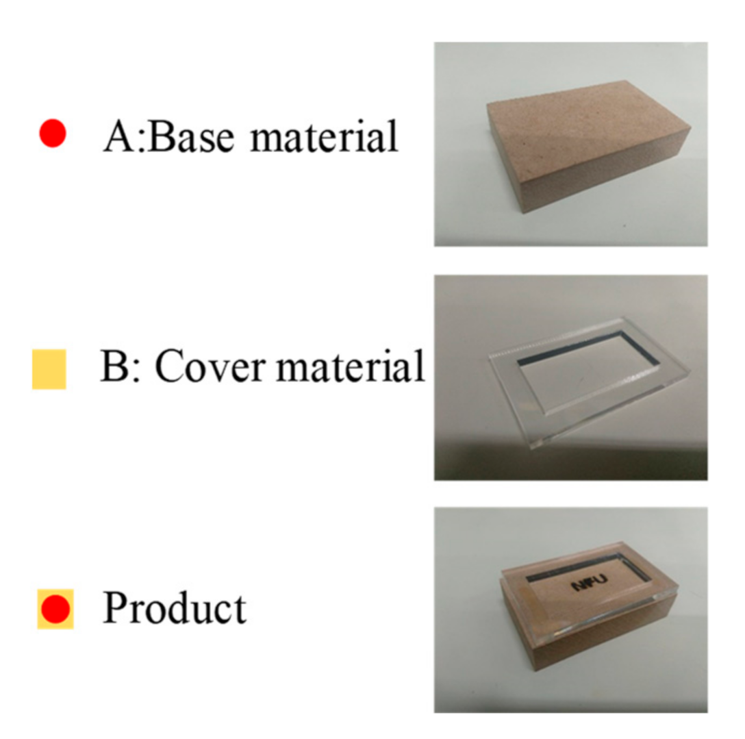
Figure 24. The material list and final products are shown in
Figure 25.
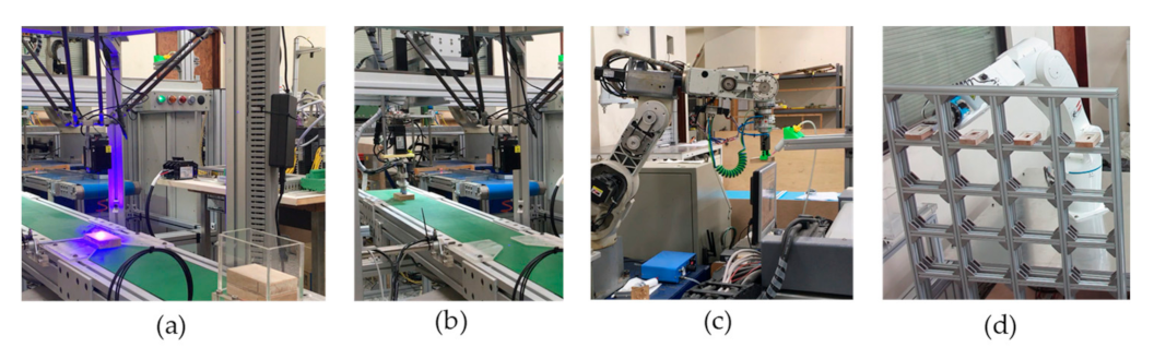
Figure 26a shows the first station, i.e., the Feeding Station. When the production line starts, Base Material A is automatically conveyed from the Feeding Station to the Laser-Engraving Station, which is the second station. The laser-engraving machine engraves the uploaded and scanned picture to the control interface in Base Material A.
Figure 26b shows the third station, i.e., the Automated Optical Inspection Station, which is mainly used for inspection of the workpiece to determine whether the product is well-produced.
Figure 26c shows the fourth station, i.e., the Gluing System. After Base Material A is laser-engraved, it is allocated for subsequent assembly operations.
Figure 26d shows the fifth station, which is the Assembly and Warehousing Station. On the assembly platform, Cover Material B is automatically picked up and assembled onto Base Material A. After this process, the product is reserved for storage.

