
A Pentaband Compound Reconfigurable Antenna for 5G and Multi-Standard Sub-6GHz Wireless Applications


 ,
,  , , ,
, , ,  and
and
Abstract
:1. Introduction
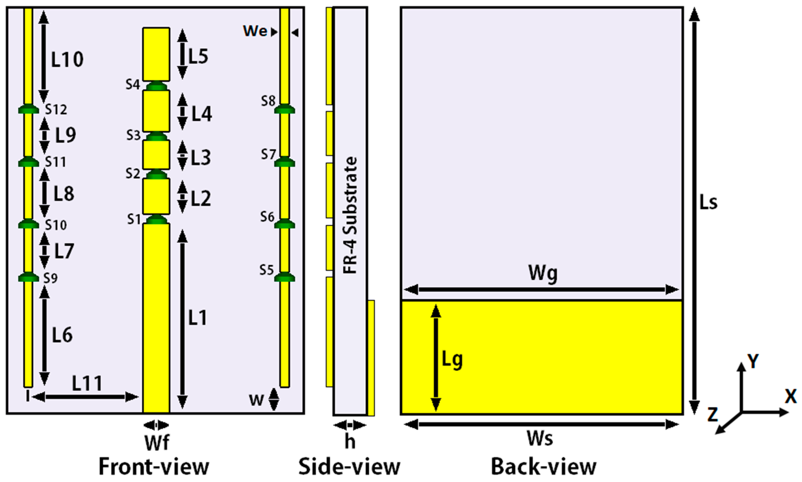
2. Design Methodology and Geometry of the Proposed Antenna
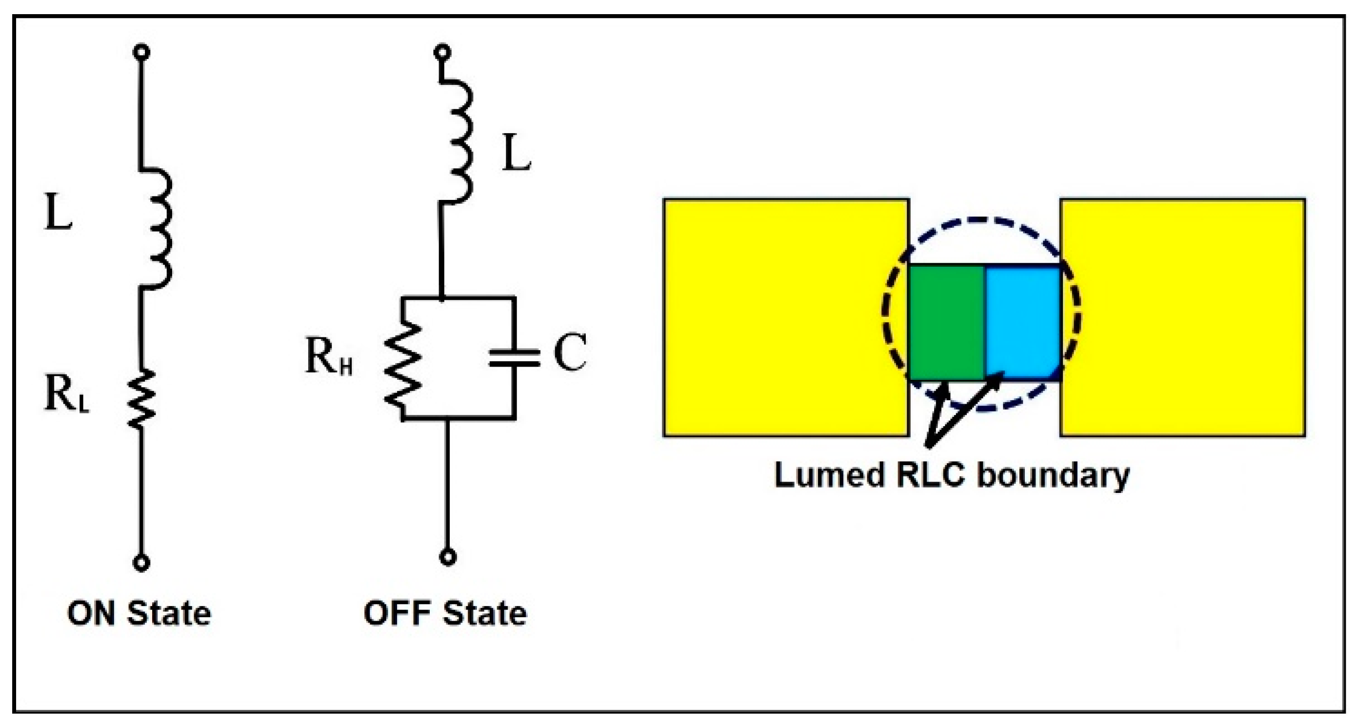
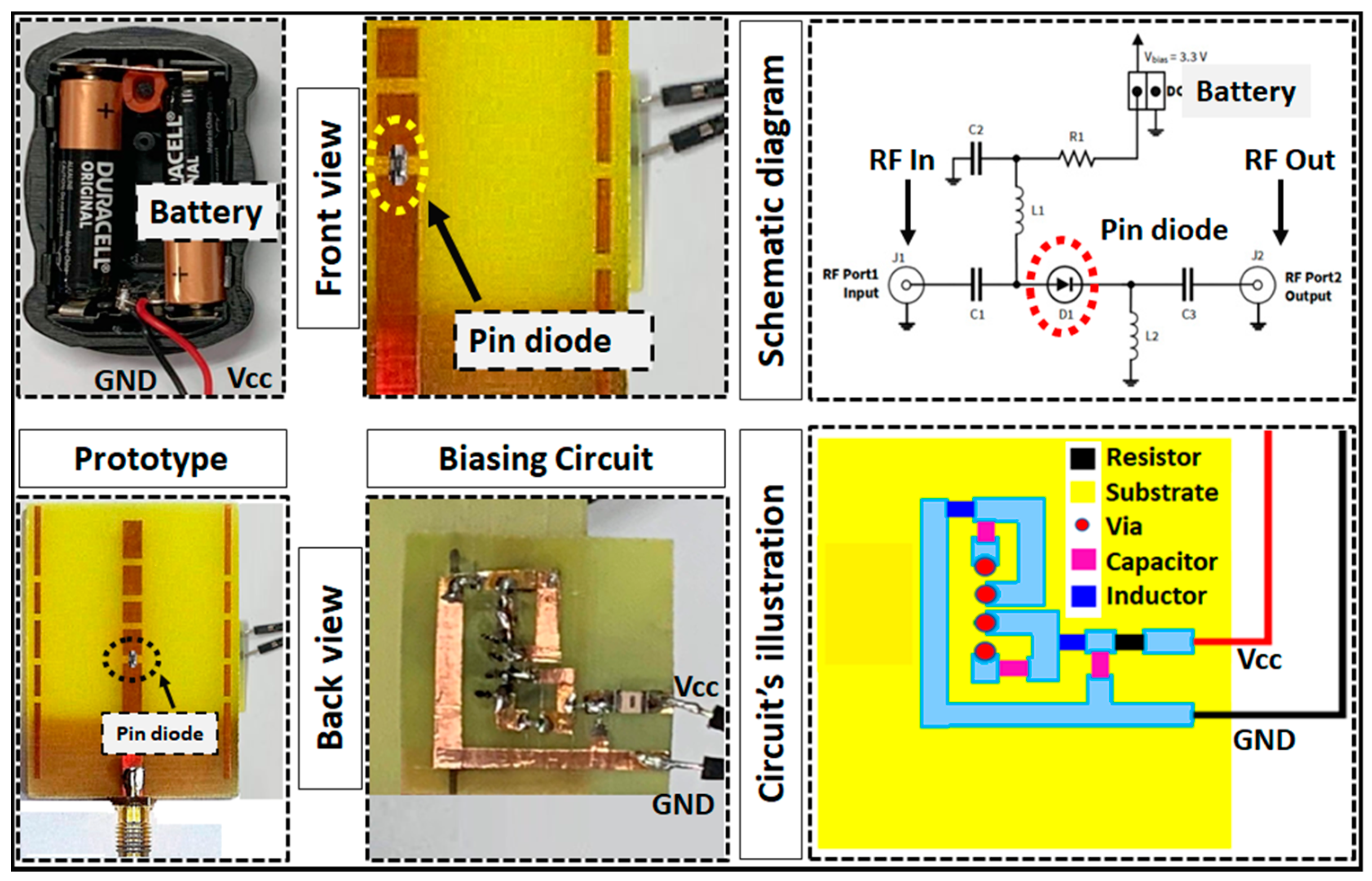
2.1. Switching Technique
2.2. Switching Configurations:
2.3. Parametric Analysis:
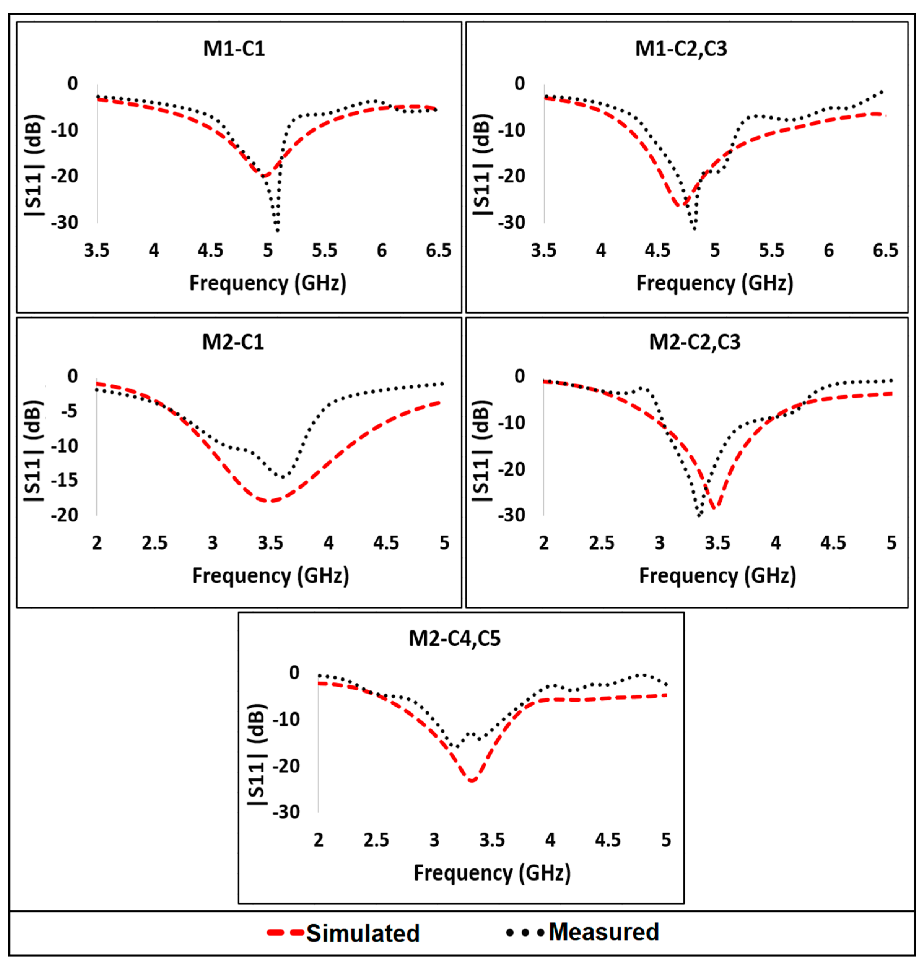
3. Experimental Results and Analysis
3.1. Operation in Mode 1
3.2. Operation in Mode 2
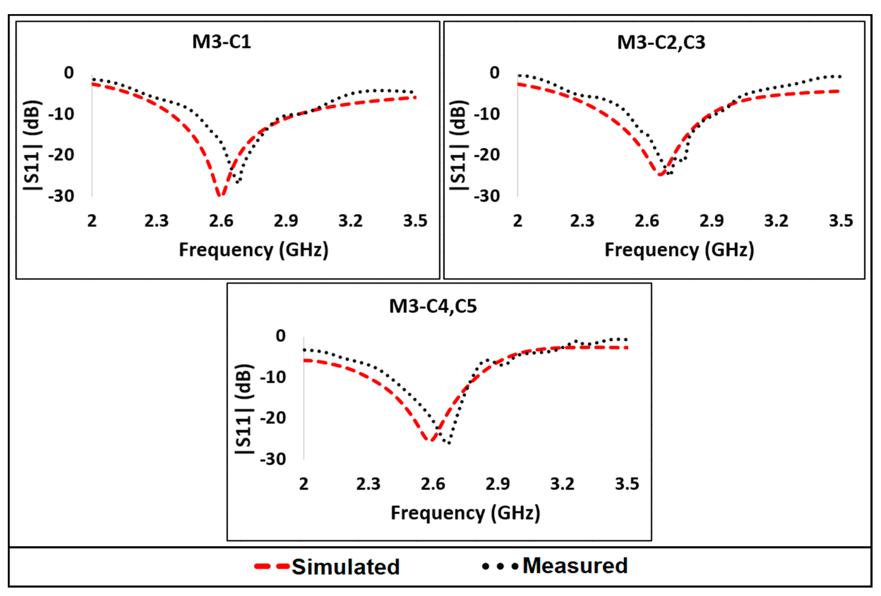
3.3. Operation in Mode 3
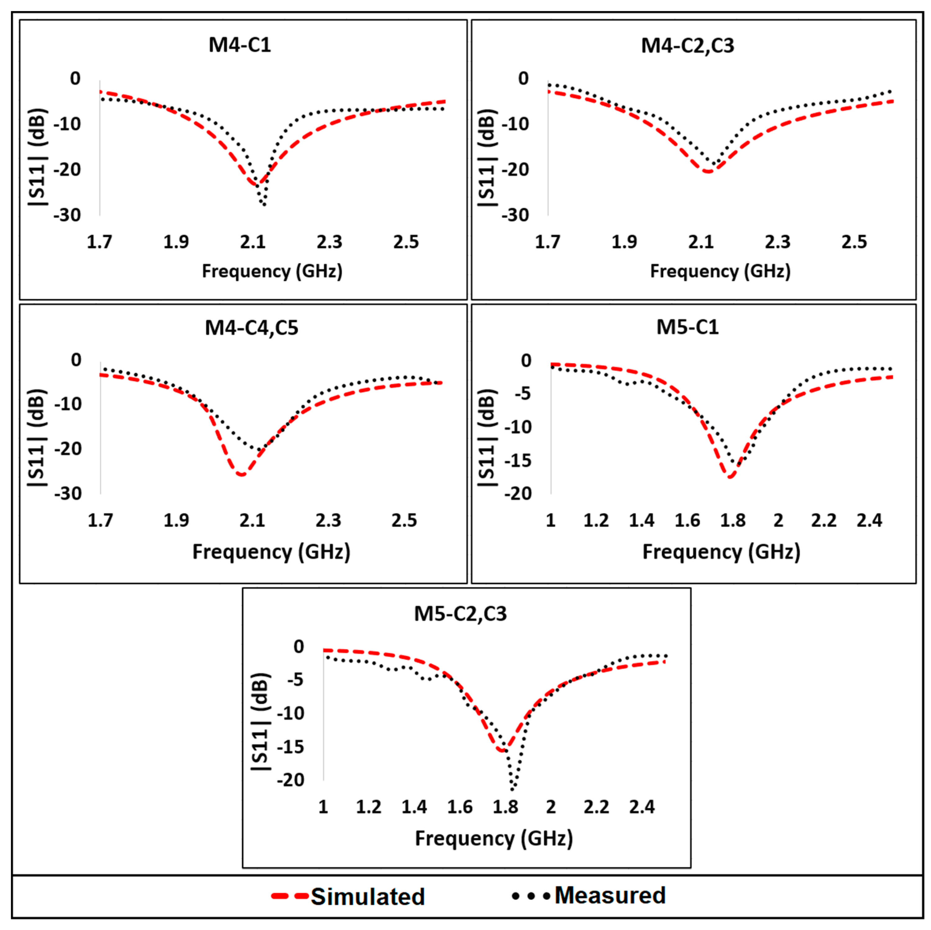
3.4. Operation in Mode 4
3.5. Operation in Mode 5
4. Conclusions
Author Contributions
Funding
Data Availability Statement
Conflicts of Interest
References
- Marcus, M.J. 5G and IMT for 2020 and beyond [spectrum policy and regulatory issues]. IEEE Wirel. Commun. 2015, 22, 2–3. [Google Scholar] [CrossRef]
- Rappaport, T.S.; Sun, S.; Mayzus, R.; Zhao, H.; Azar, Y.; Wang, K.; Wong, G.N.; Schulz, J.K.; Samimi, M.; Gutierrez, F. Millimeter wave mobile communications for 5G cellular: It will work! IEEE Access 2013, 1, 335–349. [Google Scholar] [CrossRef]
- Jenath, M.; Nagarajan, V. Review on frequency reconfigurable antenna for wireless applications. In Proceedings of the 2017 IEEE International Conference on Communication and Signal Processing (ICCSP), Chennai, India, 6–8 April 2017; pp. 2240–2245. [Google Scholar]
- Ullah, S.; Ullah, S.; Ahmad, I.; Khan, W.U.R.; Ahmad, T.; Habib, U.; Albreem, A.M.; Alsharif, M.H.; Uthansakul, P. Frequency Reconfigurable Antenna for Portable Wireless Applications. Comput. Mater. Contin. 2021, 68, 3015–3027. [Google Scholar] [CrossRef]
- Shereen, K.M.; Khattak, I.M.; Witjaksono, G. A brief review of frequency, radiation pattern, polarization, and compound reconfigurable antennas for 5G applications. J. Comput. Electron. 2019, 18, 1065–1102. [Google Scholar] [CrossRef]
- Borhani, M.; Rezaei, P.; Valizade, A. Design of a Reconfigurable Miniaturized Microstrip Antenna for Switchable Multiband Systems. IEEE Antennas Wirel. Propag. Lett. 2016, 15, 822–825. [Google Scholar] [CrossRef]
- Lee, S.W.; Sung, Y. Compact Frequency Reconfigurable Antenna for LTE/WWAN Mobile Handset Applications. IEEE Trans. Antennas Propag. 2015, 63, 4572–4577. [Google Scholar] [CrossRef]
- Ojaroudi Parchin, N.; Jahanbakhsh Basherlou, H.; Al-Yasir, Y.I.A.; Abd-Alhameed, R.A.; Abdulkhaleq, A.M.; Noras, J.M. Recent Developments of Reconfigurable Antennas for Current and Future Wireless Communication Systems. Electronics 2019, 8, 128. [Google Scholar] [CrossRef] [Green Version]
- Deshmukh, V.Y.; Chorage, S.S. Review of Reconfigurable Antennas for Future Wireless Communication. In Proceedings of the 2020 International Conference on Emerging Smart Computing and Informatics (ESCI), Pune, India, 12–14 March 2020; pp. 28–33. [Google Scholar] [CrossRef]
- Hasan, M.N.; Seo, M. Compact omnidirectional 28 GHz 2 × 2 MIMO antenna array for 5G communications. In Proceedings of the 2018 International Symposium on Antennas and Propagation (ISAP), Busan, Korea, 23–26 October 2018; pp. 1–2. [Google Scholar]
- Awan, W.A.; Ghaffar, A.; Hussain, N.; Li, X.J. A frequency reconfigurable flexible antenna for multiple mobile applications. In Proceedings of the 2019 IEEE Asia-Pacific Microwave Conference (APMC), Singapore, Singapore, 10–13 December 2019; pp. 813–815. [Google Scholar]
- Shah, I.A.; Hayata, S.; Basir, A.; Zada, M.; Shah, S.A.A.; Ullah, S. Design and analysis of a hexa-band frequency reconfigurable antenna for wireless communication. AEU—Int. J. Electron. Commun. 2019, 98, 80–88. [Google Scholar] [CrossRef]
- Bharadwaj, S.S.; Sipal, D.; Yadav, D.; Koul, S.K. A Compact Tri-Band Frequency Reconfigurable Antenna for LTE/Wi-Fi/ITS Application. Prog. Electromagn. Res. M 2020, 91, 59–67. [Google Scholar] [CrossRef]
- Ghaffar, A.; Li, X.J.; Seet, B.C.; Awan, W.A.; Hussain, N. Compact Multiband Frequency Reconfigurable Antenna for 5G Communications. In Proceedings of the 29th International Telecommunication Networks and Applications Conference (ITNAC), Auckland, New Zealand, 27–29 November 2019; pp. 1–3. [Google Scholar]
- Shahgholi, A.; Moradi, G.; Abdipour, A. Low-Profile Frequency-Reconfigurable LTE-CRLH Antenna for Smartphones. IEEE Access 2020, 8, 26487–26494. [Google Scholar] [CrossRef]
- Hussain, N.; Awan, W.A.; Naqvi, S.I.; Ghaffar, A.; Zaidi, A.; Naqvi, S.A.; Iftikhar, A.; Li, X.J. A Compact Flexible Frequency Reconfigurable Antenna for Heterogeneous Applications. IEEE Access 2020, 8, 173298–173307. [Google Scholar] [CrossRef]
- Ghaffar, A.; Li, X.J.; Awan, W.A.; Hussain, N. A Compact Multiband Multi-Mode Frequency Reconfigurable Antenna for Portable devices. In Proceedings of the 2020 International Conference on UK-China Emerging Technologies (UCET), Glasgow, UK, 20–21 August 2020; pp. 1–4. [Google Scholar]
- Iqbal, A.; Smida, A.; Abdulrazak, L.F.; Saraereh, O.A.; Mallat, N.K.; Elfergani, I.; Kim, S. Low-Profile Frequency Reconfigurable Antenna for Heterogeneous Wireless Systems. Electronics 2019, 8, 976. [Google Scholar] [CrossRef] [Green Version]
- Jin, G.; Deng, C.; Yang, J.; Xu, Y.; Liao, S. A New Differentially-Fed Frequency Reconfigurable Antenna for WLAN and Sub-6GHz 5G Applications. IEEE Access 2019, 7, 56539–56546. [Google Scholar] [CrossRef]
- Jin, G.; Deng, C.; Xu, Y.; Yang, J.; Liao, S. Differential Frequency-Reconfigurable Antenna Based on Dipoles for Sub-6 GHz 5G and WLAN Applications. IEEE Antennas Wirel. Propag. Lett. 2020, 19, 472–476. [Google Scholar] [CrossRef]
- Li, Y.; Zhao, Z.; Tang, Z.; Yin, Y. Differentially Fed, Dual-Band Dual-Polarized Filtering Antenna with High Selectivity for 5G Sub-6 GHz Base Station Applications. IEEE Trans. Antennas Propag. 2020, 68, 3231–3236. [Google Scholar] [CrossRef]
- Ullah, S.; Ahmad, I.; Raheem, Y.; Ullah, S.; Ahmad, T.; Habib, U. Hexagonal shaped CPW Feed based Frequency Reconfigurable Antenna for WLAN and Sub-6 GHz 5G applications. In Proceedings of the 2020 International Conference on Emerging Trends in Smart Technologies (ICETST), Karachi, Pakistan, 2–27 March 2020; pp. 1–4. [Google Scholar]
- Dildar, H.; Althobiani, F.; Ahmad, I.; Khan, W.U.R.; Ullah, S.; Mufti, N.; Ullah, S.; Muhammad, F.; Irfan, M.; Glowacz, A. Design and Experimental Analysis of Multiband Frequency Reconfigurable Antenna for 5G and Sub-6 GHz Wireless Communication. Micromachines 2021, 12, 32. [Google Scholar] [CrossRef] [PubMed]
- Raman, S.; Timmons, N.; Morrison, J. Gain enhanced pattern reconfigurable planar yagi-uda antenna on coplanar structure. Electron. Lett. 2013, 49, 1593–1595. [Google Scholar] [CrossRef]
- Barakali, B.; Ford, K.L.; Khamas, S. A pattern reconfigurable microstrip dipole antenna with PRS gain enhancement. In Proceedings of the 2017 11th European Conference on Antennas and Propagation (EUCAP), Paris, France, 19–24 March 2017; pp. 3131–3134. [Google Scholar]
- Tian, H.; Jiang, L.J.; Itoh, T. A Compact Single-Element Pattern Reconfigurable Antenna with Wide-Angle Scanning Tuned by a Single Varactor. Prog. Electromagn. Res. 2019, 92, 137–150. [Google Scholar] [CrossRef] [Green Version]
- Mathur, S.A.P.; Chandran, A.R.; Timmons, N.; Morrison, J.; Raman, S. 2.45 GHz Pattern Reconfigurable Antenna for Wireless Sensor Network applications. In Proceedings of the 2019 URSI Asia-Pacific Radio Science Conference (AP-RASC), New Delhi, India, 9–15 March 2019; pp. 1–4. [Google Scholar]
- Jais, M.I.; Jamlos, M.F.; Jusoh, M.; Sabapathy, T.; Kamarudin, M.R. 2.45 GHz beam-steering textile antenna for WBAN application. In Proceedings of the 2013 IEEE Antennas and Propagation Society International Symposium (APSURSI), Orlando, FL, USA, 7 July 2013–13 July 2013; pp. 200–201. [Google Scholar]
- Hafeez, F.; Sheikh, U.U.; Alkhaldi, N.; Al Garni, H.Z.; Arfeen, Z.A.; Khalid, S.A. Insights and strategies for an autonomous vehicle with a sensor fusion innovation: A fictional outlook. IEEE Access 2020, 8, 135162–135175. [Google Scholar] [CrossRef]
- Lu, Z.-L.; Yang, X.-X.; Tan, G.-N. A Multidirectional Pattern-Reconfigurable Patch Antenna with CSRR on the Ground. IEEE Antennas Wirel. Propag. Lett. 2017, 16, 416–419. [Google Scholar] [CrossRef]
- Ma, W.D.; Wang, G.; Wang, Y.-W.; Zong, B. Compact Microstrip Antenna with Pattern-Reconfigurable Characteristic. Radio Eng. 2017, 26, 662–667. [Google Scholar] [CrossRef]
- Ghaffar, A.; Li, X.J.; Awan, W.A.; Naqvi, A.H.; Hussain, N.; Alibakhshikenari, M.; Limiti, E. A Flexible and Pattern Reconfigurable Antenna with Small Dimensions and Simple Layout for Wireless Communication Systems Operating over 1.65–2.51 GHz. Electronics 2021, 10, 601. [Google Scholar] [CrossRef]
- Zainarry, S.N.M.; Nguyen-Trong, N.; Fumeaux, C. A Frequency- and Pattern-Reconfigurable Two-Element Array Antenna. IEEE Antennas Wirel. Propag. Lett. 2018, 17, 617–620. [Google Scholar] [CrossRef]
- Shereen, K.M.; Khattak, I.M.; Al-Hasan, M. A Frequency and Radiation Pattern Combo-Reconfigurable Novel Antenna for 5G Applications and Beyond. Electronics 2020, 9, 1372. [Google Scholar] [CrossRef]
- Ismail, M.F.; Rahim, M.K.A.; Hamid, M.R.; Majid, H.A.; Omar, A.H.; Nur, L.O.; Bambang, S. NugrohoDual-band pattern reconfigurable antenna using electromagnetic band-gap structure. AEU—Int. J. Electron. Commun. 2021, 130, 153571. [Google Scholar] [CrossRef]
- Iqbal, A.; Smida, A.; Mallat, N.K.; Ghayoula, R.; Elfergani, I.; Rodriguez, J.; Kim, S. Frequency and Pattern Reconfigurable Antenna for Emerging Wireless Communication Systems. Electronics 2019, 8, 407. [Google Scholar] [CrossRef] [Green Version]
- Zhu, Z.; Wang, P.; You, S.; Gao, P. A Flexible Frequency and Pattern Reconfigurable Antenna for Wireless Systems. Prog. Electromagn. Res. 2018, 76, 63–70. [Google Scholar] [CrossRef]
- Han, L.; Wang, C.; Zhang, W.; Ma, R.; Zeng, Q. Design of frequency- and pattern-reconfigurable wideband slot antenna. Int. J. Antennas Propag. 2018, 1–7. [Google Scholar] [CrossRef] [Green Version]
- Ahmad, I.; Dildar, H.; Khan, W.U.R.; Shah, S.A.A.; Ullah, S.; Ullah, S.; Umar, S.M.; Albreem, M.A.; Alsharif, M.H.; Vasudevan, K. Design and Experimental Analysis of Multiband Compound Reconfigurable 5G Antenna for Sub-6 GHz Wireless Applications. Wirel. Commun. And. Mob. Comput. 2021, 2021, 5588105. [Google Scholar] [CrossRef]


| Parameter | Value (mm) | Parameter | Value (mm) |
|---|---|---|---|
| Ws | 32 | L4 | 4.7 |
| Ls | 46 | L5 | 6 |
| Wg | 20 | L6 | 12 |
| Lg | 12.5 | L7 | 5 |
| W | 3 | L8 | 6 |
| Wf | 3 | L9 | 5 |
| L1 | 21.5 | L10 | 11 |
| L2 | 4.1 | L11 | 12.5 |
| L3 | 3.3 | H | 1.6 |
| We | 1 |
| Modes | Special Cases |
|---|---|
| Mode-1 (ON: None, OFF: S1, S2, S3 & S4) | C1 (OFF: S5–S12), C2 (ON: S6 & S7), C3 (ON: S10 & S11) |
| Mode-2 (ON: S1, OFF: S2, S3 & S4) | C1 (OFF: S5–S12), C2 (ON: S6 & S7), C3 (ON: S10 & S11), C4 (ON: S5-S8, S11 & S12), C5 (ON: S7–S12) |
| Mode-3 (ON: S1 & S2, OFF: S3 & S4) | C1 (OFF: S5–S12), C2 (ON: S6, S7 & S8), C3 (ON: S10, S11 & S12), C4 (ON: S5–S8 & S10–S12), C5 (ON: S6-S12) |
| Mode-4 (ON: S1, S2, S3, OFF: S4) | C1 (OFF: S5–S12), C2 (ON: S6, S7 & S8), C3 (ON: S10, S11 & S12), C4 (ON: S5–S8 & S10–S12), C5 (ON: S6–S12) |
| Mode-5 (ON: S1–S4, OFF: None) | C1 (OFF: S5–S12), C2 (ON: S6, S7 & S8), C3 (ON: S10, S11 & S12) |
| Mode | Case and Switch Configuration | Operating Frequency Band (GHz) | Peak Gain (dBi) | Main Beam Direction (at φ = 0°) | Beam Steering Angle | |
|---|---|---|---|---|---|---|
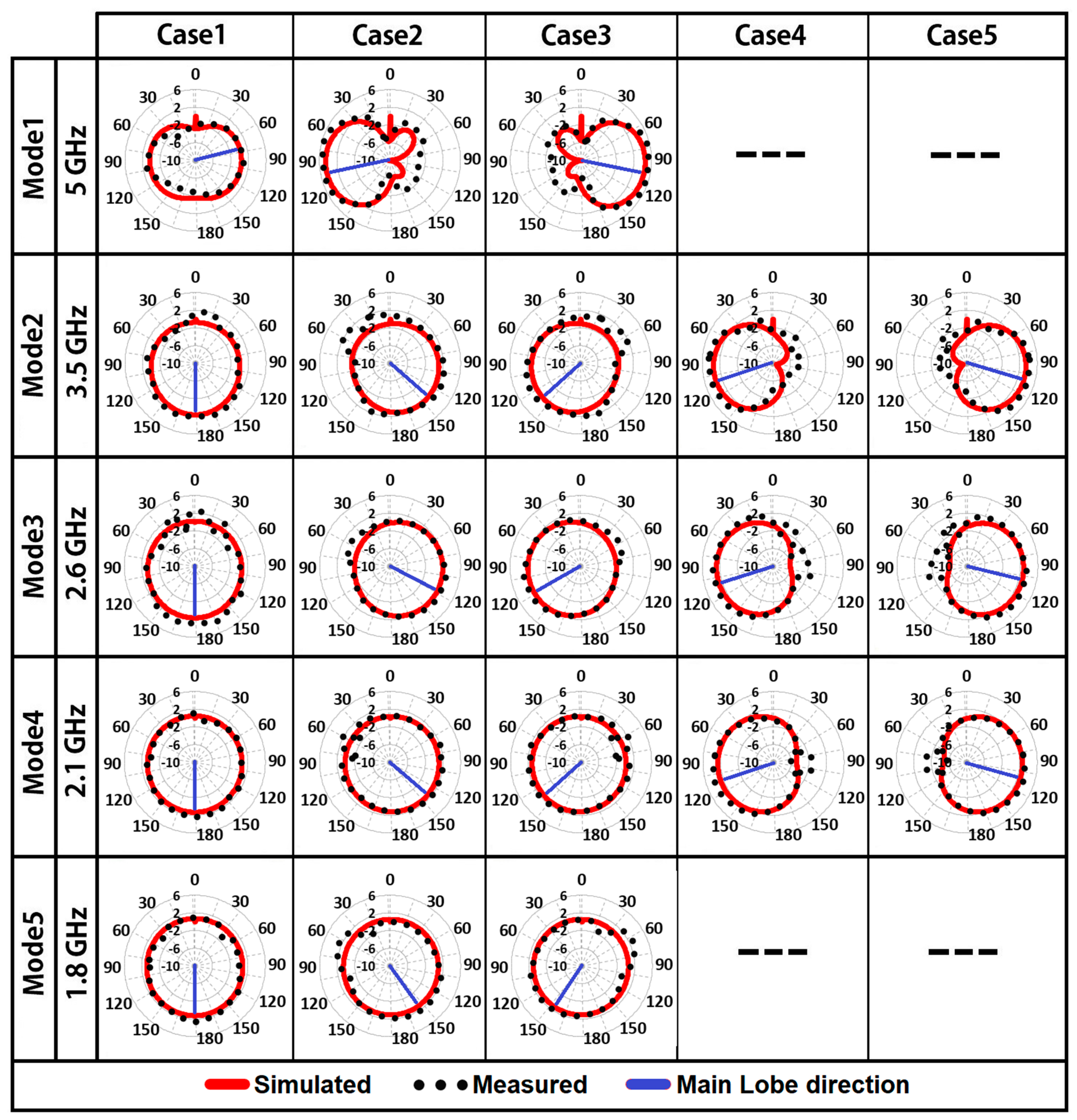
| 1 | (1) When all Switches are off | 4.52–5.39 (870) | 1.28 | +85° | 0° | |
| (2) When S6 & 7 are on | 5 | 4.25–5.60 (1350) | 4.67 | −95° | −180° | |
| (3) When S10 & 11 are on | 4.25–5.60 (1350) | 4.67 | +95° | +10° | ||
| 2 | (1) When only S1 is on | 2.96–4.17 (1210) | 1.87 | 180° | 0° | |
| (2) When S1, 6 & 7 are on | 3.00–3.92 (920) | 1.57 | +140° | +40° | ||
| (3) When S1, 10 & 11 are on | 3.5 | 3.00–3.92 (920) | 1.57 | −140° | −40° | |
| (4) When S1, 5, 6, 7, 8, 11 & 12 are on | 2.85–3.67 (820) | 3.64 | −100° | −80° | ||
| (5) When S1, 7, 8, 9, 10, 11 & 12 are on | 2.85–3.67 (820) | 3.64 | +100° | +80° | ||
| 3 | (1) When S1 & 2 are on | 2.36–2.95 (590) | 1.74 | 180° | 0° | |
| (2) When S1, 2, 6, 7 & 8 are on | 2.40–2.90 (500) | 2.11 | +117° | +63° | ||
| (3) When S1, 2, 10, 11 & 12 are on | 2.6 | 2.40–2.90 (500) | 2.11 | −117° | −63° | |
| (4) When S1, 2, 5, 6, 7, 8, 10, 11 & 12 are on | 2.29–2.80 (510) | 2.9 | −103° | −77° | ||
| (5) When S1, 2, 6, 7, 8, 9, 10, 11 & 12 are on | 2.29–2.80 (510) | 2.9 | +103° | +77° | ||
| 4 | (1) When S1, 2 & 3 are on | 1.95–2.30 (350) | 1.51 | 180° | 0° | |
| (2) When S1, 2, 3, 6, 7 & 8 are on | 1.96–2.31 (350) | 1.33 | +146° | +34° | ||
| (3) When S1, 2, 3, 10, 11 & 12 are on | 2.1 | 1.96–2.31 (350) | 1.33 | −146° | −34° | |
| (4) When S1, 2, 3, 5, 6, 7, 8, 10, 11 & 12 are on | 1.97–2.28 (310) | 2.80 | −107° | −73° | ||
| (5) When S1, 2, 3, 6, 7, 8, 9, 10, 11 & 12 are on | 1.97–2.28 (310) | 2.80 | +107 ° | +73° | ||
| 5 | (1) When S1, 2, 3 & 4 are on | 1.67–1.90 (230) | 1.25 | 180° | 0° | |
| (2) When S1, 2, 3, 4, 6, 7 & 8 are on | 1.8 | 1.68–1.90 (220) | 1.15 | +154° | +26° | |
| (3) When S1, 2, 3, 4, 10, 11 & 12 are on | 1.68–1.90 (220) | 1.15 | −154° | −26° |
| Ref. No. | Size (Ls × Ws) | No. of switches | Type of Switches | No. of Operating Frequency Bands | Max Number of Beams | Bandwidth (MHz) | Peak Gains (dBi) |
|---|---|---|---|---|---|---|---|
| [32] | 45 × 50 | 2 | Pin diode | 1 | 3 | 800 | 2.2 |
| [33] | 160.9 × 151.5 | 2 | Varactor | 2 | 2 | 730 | 9 |
| [34] | 112 × 52 | 18 | NMOs | 2 | 8 | 1400/1501 | 3.8/8.3 |
| [35] | 113 × 113 | 14 | Pin diode | 2 | 3 | N/A | 6.2/6.6 |
| [36] | 23 × 31 | 3 | Pin diode | 2 | 4 | 1700/1200 | 4.01/4.60 |
| [37] | 42 × 44 | 8 | Pin diode | 2 | 2 | 160/220 | NG |
| [38] | 40 × 30 | 4 | Pin diode | 2 | 3 | 400/500 | 2.24/2.76 |
| This work | 46 × 32 | 12 | Pin diode | 5 | 5 | 230/350/590 /1210/1350 | 1.25/2.80/2.90 /3.64/4.67 |
Publisher’s Note: MDPI stays neutral with regard to jurisdictional claims in published maps and institutional affiliations. |
© 2021 by the authors. Licensee MDPI, Basel, Switzerland. This article is an open access article distributed under the terms and conditions of the Creative Commons Attribution (CC BY) license (https://creativecommons.org/licenses/by/4.0/).
Share and Cite
Ahmad, I.; Khan, W.U.R.; Dildar, H.; Ullah, S.; Ullah, S.; Mufti, N.; Kamal, B.; Ahmad, T.; Ghaffar, A.; Hussien, M.I. A Pentaband Compound Reconfigurable Antenna for 5G and Multi-Standard Sub-6GHz Wireless Applications. Electronics 2021, 10, 2526. https://doi.org/10.3390/electronics10202526
Ahmad I, Khan WUR, Dildar H, Ullah S, Ullah S, Mufti N, Kamal B, Ahmad T, Ghaffar A, Hussien MI. A Pentaband Compound Reconfigurable Antenna for 5G and Multi-Standard Sub-6GHz Wireless Applications. Electronics. 2021; 10(20):2526. https://doi.org/10.3390/electronics10202526
Chicago/Turabian StyleAhmad, Ikhlas, Wasi Ur Rehman Khan, Haris Dildar, Sadiq Ullah, Shakir Ullah, Naveed Mufti, Babar Kamal, Toufeeq Ahmad, Adnan Ghaffar, and Mousa I. Hussien. 2021. "A Pentaband Compound Reconfigurable Antenna for 5G and Multi-Standard Sub-6GHz Wireless Applications" Electronics 10, no. 20: 2526. https://doi.org/10.3390/electronics10202526
APA StyleAhmad, I., Khan, W. U. R., Dildar, H., Ullah, S., Ullah, S., Mufti, N., Kamal, B., Ahmad, T., Ghaffar, A., & Hussien, M. I. (2021). A Pentaband Compound Reconfigurable Antenna for 5G and Multi-Standard Sub-6GHz Wireless Applications. Electronics, 10(20), 2526. https://doi.org/10.3390/electronics10202526