
Design of a MIMO Antenna with High Gain and Enhanced Isolation for WLAN Applications


Abstract
:1. Introduction
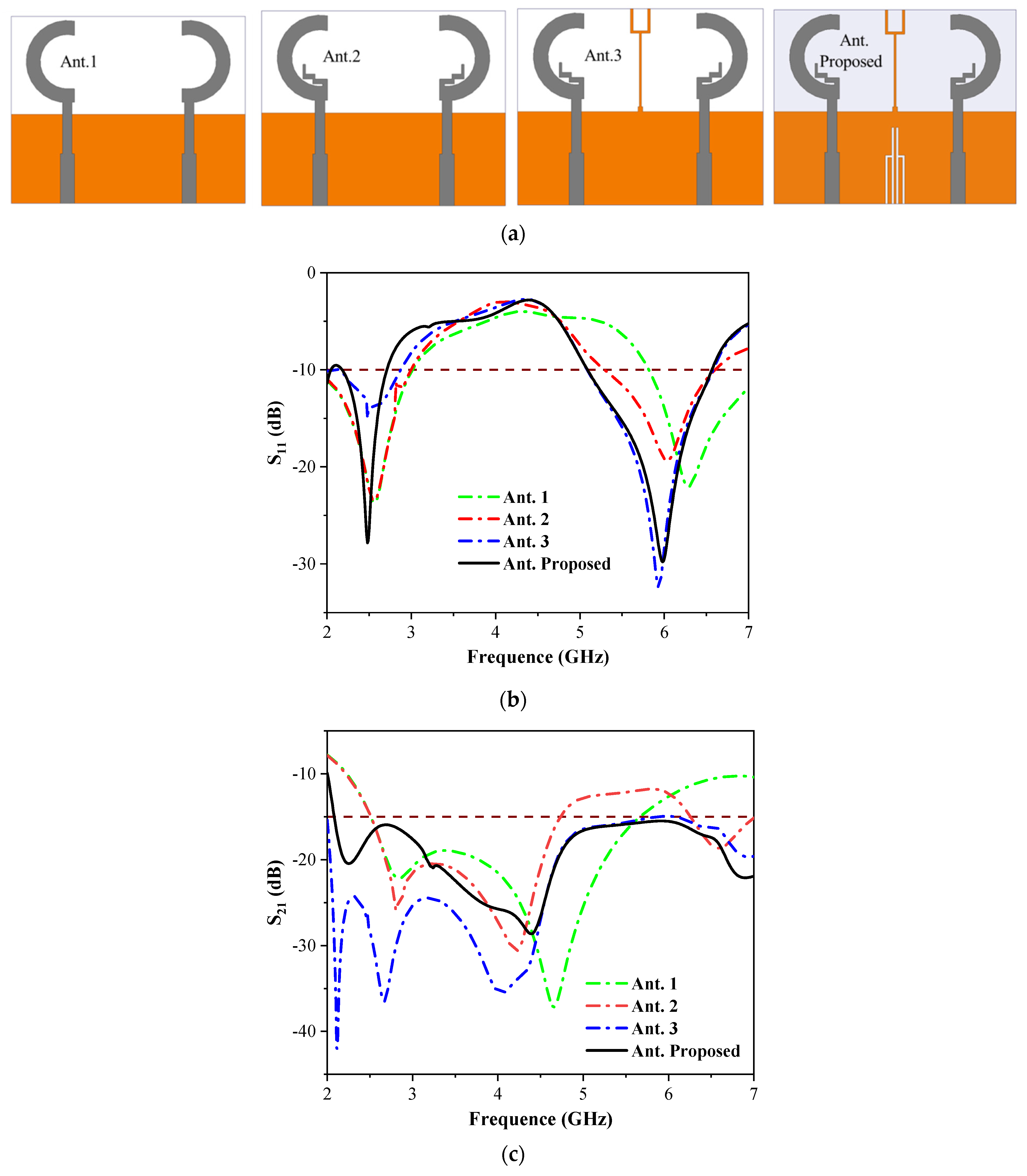
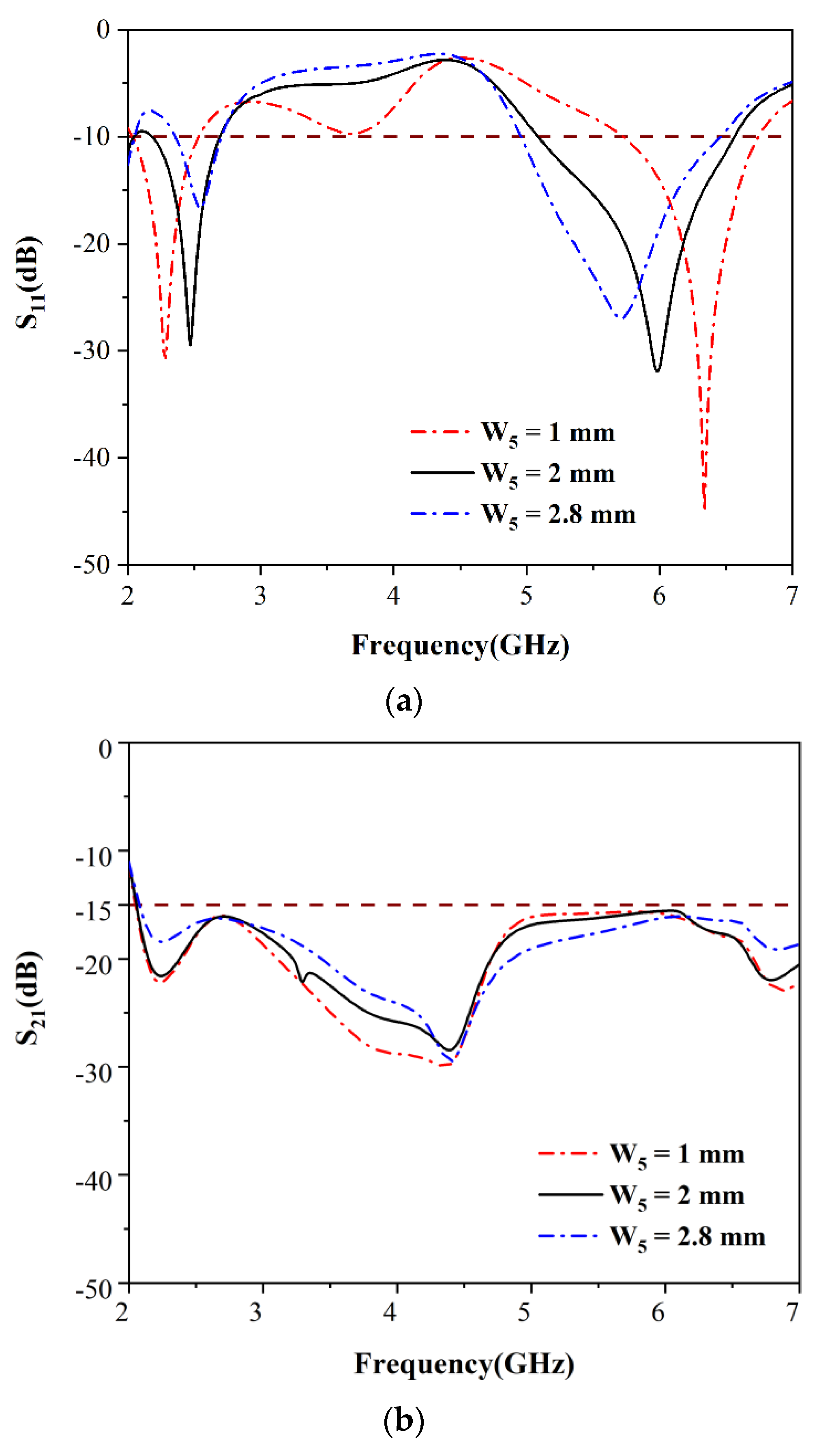
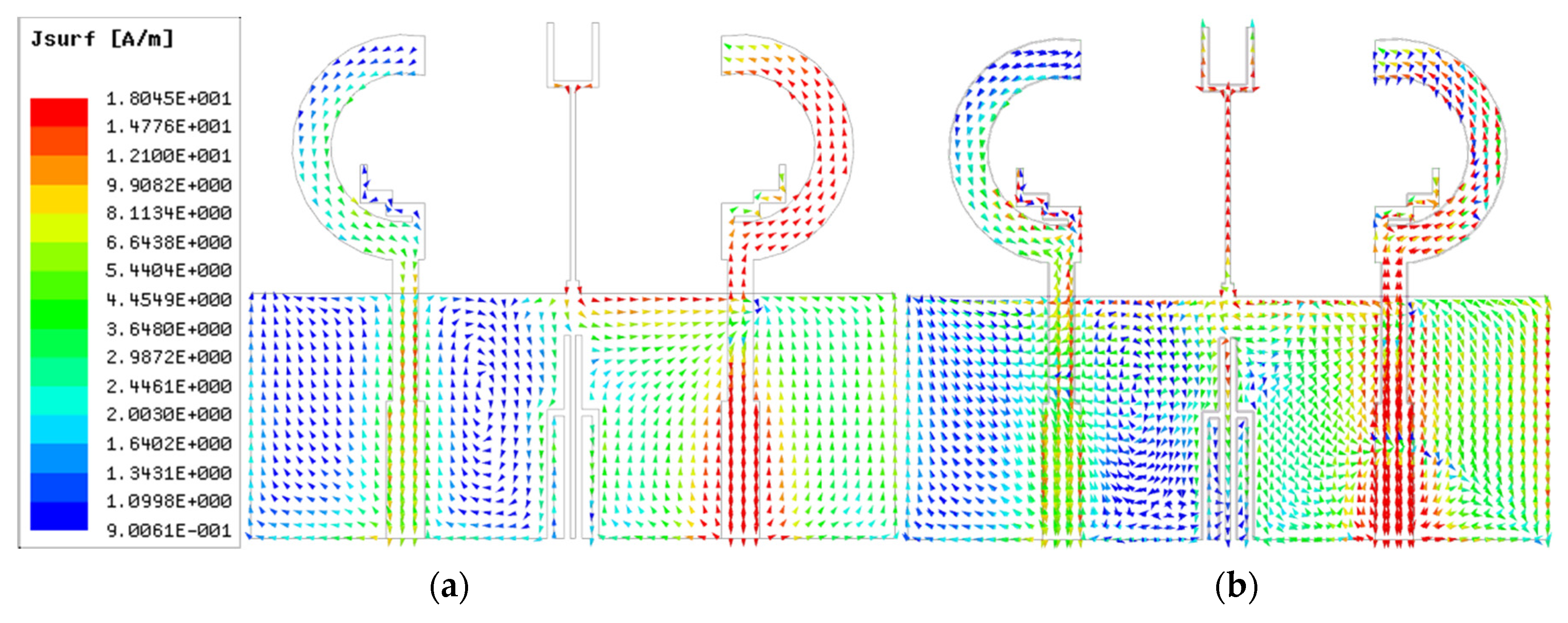
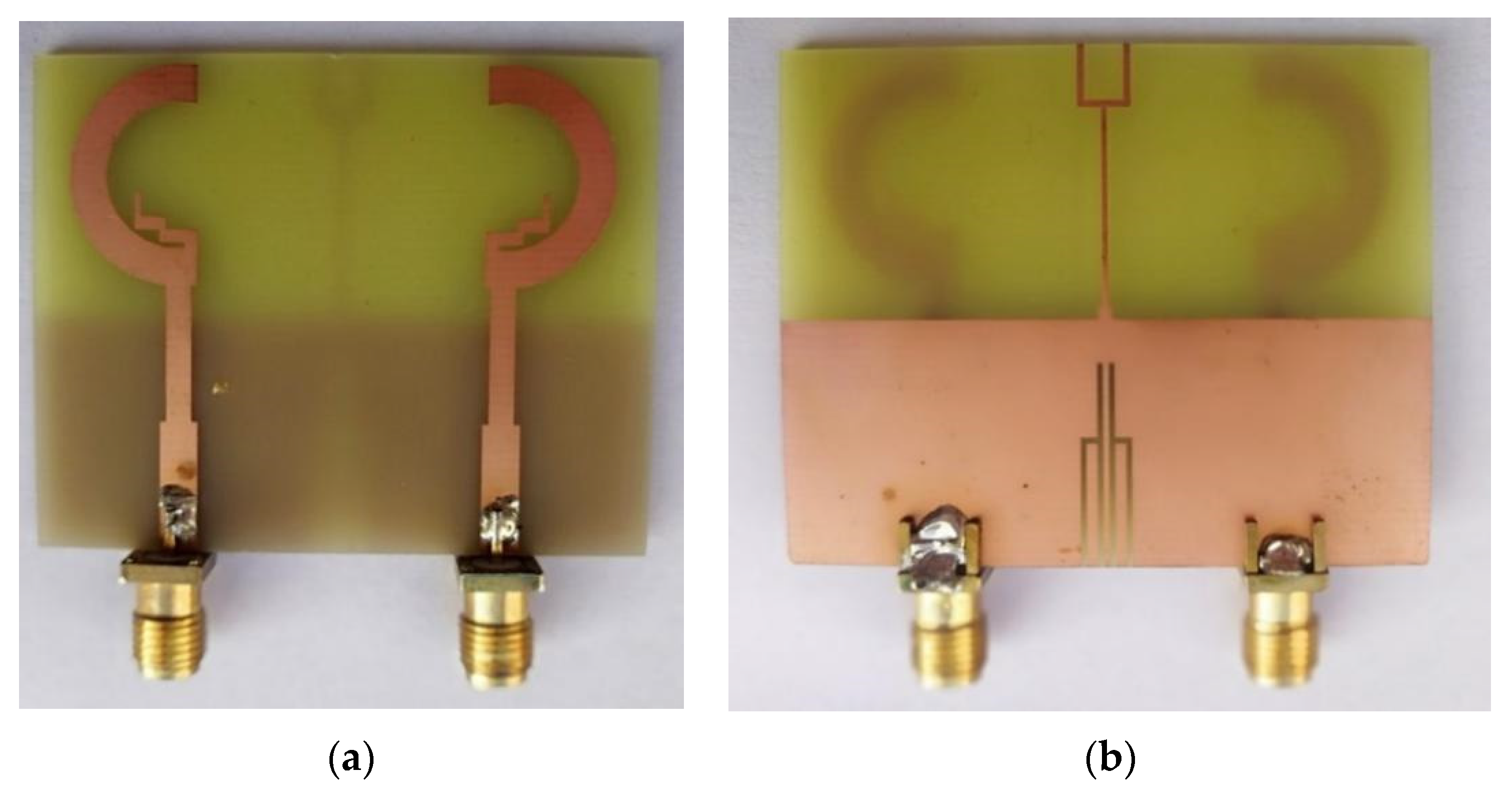
2. Antenna Design
3. Results and Discussion
4. Conclusions
Author Contributions
Funding
Data Availability Statement
Conflicts of Interest
References
- Huang, J.; Dong, G.; Cai, J.; Li, H.; Liu, G. A Quad-Port Dual-Band MIMO Antenna Array for 5G Smartphone Applications. Electronics 2021, 10, 542. [Google Scholar] [CrossRef]
- Li, M.; Jiang, L.; Yeung, K.L. A General and Systematic Method to Design Neutralization Lines for Isolation Enhancement in MIMO Antenna Arrays. IEEE Trans. Veh. Technol. 2020, 69, 6242–6253. [Google Scholar] [CrossRef]
- Yang, R.; Xi, S.; Cai, Q.; Chen, Z.; Wang, X.; Liu, G. A Compact Planar Dual-Band Multiple-Input and Multiple-Output Antenna with High Isolation for 5G and 4G Applications. Micromachines 2021, 12, 544. [Google Scholar] [CrossRef] [PubMed]
- Nirmal, P.C.; Nandgaonkar, A.B.; Nalbalwar, S.; Gupta, R.K. A Compact Dual Band and MIMO Antenna with Improved Isolation for WI-MAX and WLAN Applications. Prog. Electromagn. Res. M 2018, 68, 69–77. [Google Scholar] [CrossRef] [Green Version]
- Tran, H.H.; Nguyen-Trong, N. Performance Enhancement of MIMO Patch Antenna Using Parasitic Elements. IEEE Access 2021, 9, 30011–30016. [Google Scholar] [CrossRef]
- Hussain, R.; Khan, M.U.; Sharawi, M.S. An Integrated Dual MIMO Antenna System with Dual-Function GND-Plane Frequency-Agile Antenna. IEEE Antennas Wirel. Propag. Lett. 2018, 17, 142–145. [Google Scholar] [CrossRef]
- Gao, D.; Cao, Z.X.; Fu, S.D.; Quan, X.; Chen, P. A Novel Slot-Array Defected Ground Structure for Decoupling Microstrip Antenna Array. IEEE Trans. Antennas Propag. 2020, 68, 7027–7038. [Google Scholar] [CrossRef]
- Zeng, J.; Luk, K. A Simple Wideband Magnetoelectric Dipole Antenna with a Defected Ground Structure. IEEE Antennas Wirel. Propag. Lett. 2018, 17, 1497–1500. [Google Scholar] [CrossRef]
- Ullah, U.; Al-Hasan, M.; Koziel, S.; Mabrouk, I.B. Circular Polarization Diversity Implementation for Correlation Reduction in Wideband Low-Cost Multiple-Input-Multiple-Output Antenna. IEEE Access 2020, 8, 95585–95593. [Google Scholar] [CrossRef]
- Li, Z.; Yin, C.; Zhu, X. Compact UWB MIMO Vivaldi Antenna with Dual Band-Notched Characteristics. IEEE Access 2019, 7, 38696–38701. [Google Scholar] [CrossRef]
- Kumar, P.; Urooj, S.; Alrowais, F. Design and Implementation of Quad-Port MIMO Antenna with Dual-Band Elimination Characteristics for Ultra-Wideband Applications. Appl. Sci. 2020, 10, 1715. [Google Scholar] [CrossRef] [Green Version]
- Iqbal, A.; A Saraereh, O.; Bouazizi, A.; Basir, A. Metamaterial-Based Highly Isolated MIMO Antenna for Portable Wireless Applications. Electronics 2018, 7, 267. [Google Scholar] [CrossRef] [Green Version]
- Zhu, J.; Li, S.; Liao, S.; Xue, Q. Wideband Low-Profile Highly Isolated MIMO Antenna with Artificial Magnetic Conductor. IEEE Antennas Wirel. Propag. Lett. 2018, 17, 458–462. [Google Scholar] [CrossRef]
- Chatterjee, J.; Mohan, A.; Dixit, V. Broadband Circularly Polarized H-Shaped Patch Antenna Using Reactive Impedance Surface. IEEE Antennas Wirel. Propag. Lett. 2018, 17, 625–628. [Google Scholar] [CrossRef]
- Huang, J.; Dong, G.; Cai, Q.; Chen, Z.; Li, L.; Liu, G. Dual-Band MIMO Antenna for 5G/WLAN Mobile Terminals. Micromachines 2021, 12, 489. [Google Scholar] [CrossRef]
- Dou, Y.; Chen, Z.; Bai, J.; Cai, Q.; Liu, G. Two-Port CPW-Fed Dual-Band MIMO Antenna for IEEE 802.11 a/b/g Applications. Int. J. Antennas Propag. 2021, 2021, 5572887. [Google Scholar] [CrossRef]
- Lu, D.; Wang, L.; Yang, E.; Wang, G. Design of High-Isolation Wideband Dual-Polarized Compact MIMO Antennas with Multiobjective Optimization. IEEE Trans. Antennas Propag. 2018, 66, 1522–1527. [Google Scholar] [CrossRef] [Green Version]
- Chattha, H.T.; Latif, F.; Tahir, F.A.; Khan, M.U.; Yang, X. Small-Sized UWB MIMO Antenna with Band Rejection Capability. IEEE Access 2019, 7, 121816–121824. [Google Scholar] [CrossRef]


| Types of Antenna | WLAN MIMO Antenna |
|---|---|
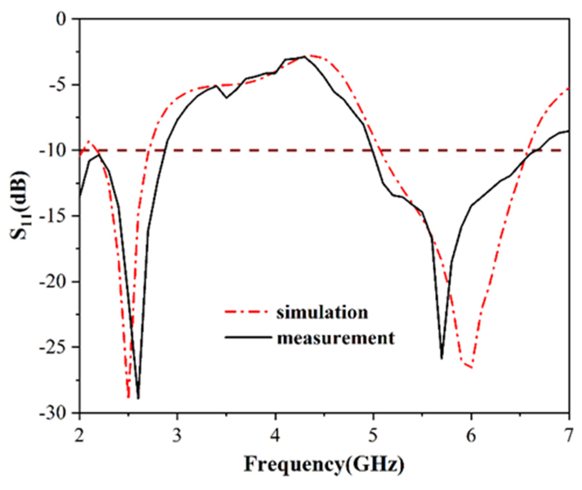
| Frequency | 2.4–2.4385 GHz and 5.725–5.8 GHz |
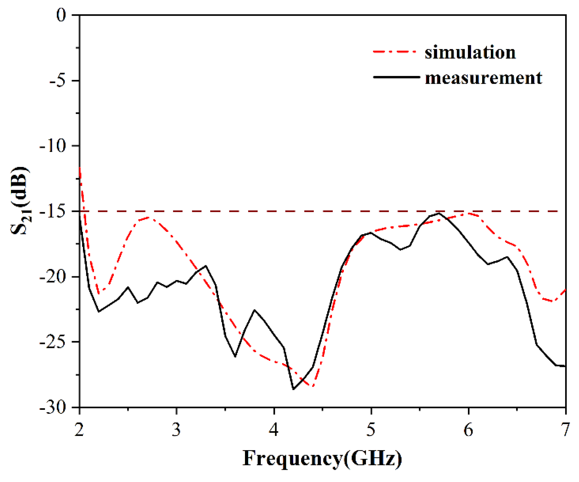
| Isolation (dB) | >15 dB |
| ECC | <0.3 |
| Parameters | Value | Parameters | Value | Parameters | Value |
|---|---|---|---|---|---|
| W1 | 23 | W2 | 0.5 | W3 | 2 |
| W4 | 2.5 | W5 | 2 | W6 | 3 |
| W7 | 10.5 | W8 | 23 | W9 | 3 |
| W10 | 0.4 | W11 | 9.5 | W12 | 1.4 |
| W13 | 0.5 | W14 | 1.3 | W15 | 0.8 |
| L1 | 2 | L2 | 1 | L3 | 4.4 |
| L4 | 11 | L5 | 10.6 | L6 | 5 |
| L7 | 0.5 | L8 | 15 | L9 | 21 |
| L10 | 5.7 | L11 | 9.5 | L12 | |
| R1 | 8.8 | R2 | 5.8 |
| Reference | Operating Frequency Bands (GHz) | Minimum Isolation (dB) | Peak Gain (dBi) | Size (mm3) |
|---|---|---|---|---|
| [4] | 2.2–3.8 | >15 | 2.8 | 30 × 26 × 1.6 |
| 5.7–6.2 | ||||
| [6] | 1.73–2.28 | >10 | 2.33 | 50 × 110 × 1.56 |
| 2.45 | ||||
| [10] | 2.9–5.3 | >14 | 4 | 26 × 26 × 0.762 |
| 5.3–5.8 | ||||
| [16] | 2.25–3.15 | >15 | 5.59 | 50 × 50 × 1.59 |
| 4.89–5.95 | 5.63 | |||
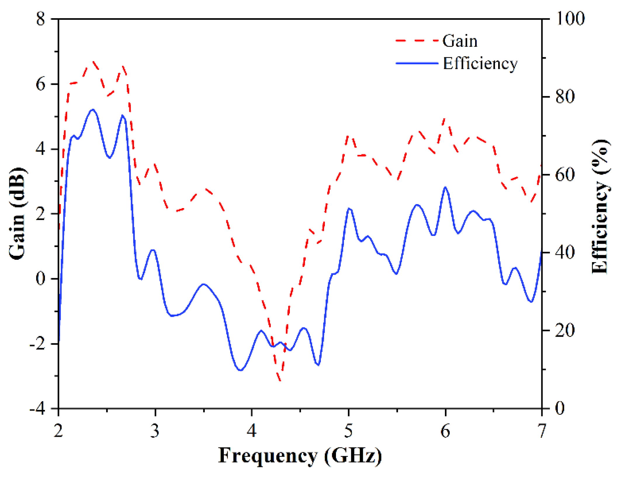
| This work | 2.12–2.8 | >15 | 6.4 | 50 × 40 × 1.59 |
| 4.95–6.65 |
Publisher’s Note: MDPI stays neutral with regard to jurisdictional claims in published maps and institutional affiliations. |
© 2021 by the authors. Licensee MDPI, Basel, Switzerland. This article is an open access article distributed under the terms and conditions of the Creative Commons Attribution (CC BY) license (https://creativecommons.org/licenses/by/4.0/).
Share and Cite
Peng, H.; Zhi, R.; Yang, Q.; Cai, J.; Wan, Y.; Liu, G. Design of a MIMO Antenna with High Gain and Enhanced Isolation for WLAN Applications. Electronics 2021, 10, 1659. https://doi.org/10.3390/electronics10141659
Peng H, Zhi R, Yang Q, Cai J, Wan Y, Liu G. Design of a MIMO Antenna with High Gain and Enhanced Isolation for WLAN Applications. Electronics. 2021; 10(14):1659. https://doi.org/10.3390/electronics10141659
Chicago/Turabian StylePeng, He, Ruixing Zhi, Qichao Yang, Jing Cai, Yi Wan, and Gui Liu. 2021. "Design of a MIMO Antenna with High Gain and Enhanced Isolation for WLAN Applications" Electronics 10, no. 14: 1659. https://doi.org/10.3390/electronics10141659
APA StylePeng, H., Zhi, R., Yang, Q., Cai, J., Wan, Y., & Liu, G. (2021). Design of a MIMO Antenna with High Gain and Enhanced Isolation for WLAN Applications. Electronics, 10(14), 1659. https://doi.org/10.3390/electronics10141659