Article

8-Port Semi-Circular Arc MIMO Antenna with an Inverted L-Strip Loaded Connected Ground for UWB Applications

1
Department of ECE, JNTUA, Andhra Pradesh, Anantapur 515002, India
2
Department of Electronics and Communication Engineering, CSPIT, Charotar University of Science and Technology (CHARUSAT), Changa 388421, India
3
Instituto de Telecomunicações, Campus Universitário de Santiago, 3810-193 Aveiro, Portugal
4
School of Engineering and Informatics, University of Bradford, Bradford BD7 1DP, UK
5
Faculty of Electronics and Communications Engineering, VIT Bhopal University, Bhopal 466114, India
6
Department of Electronics and Telecommunication Engineering, Vishwakarma Institute of Information Technology, Pune 411037, India
7
Laboratoire D’Electronique de Puissance et Commande Industrielle (LEPCI), Department of Electronics, University of Ferhat Abbas, SETIF -1-, Setif 19000, Algeria
8
Information and Comms Eng. Dept., Basrah University College of Science and Technology, Basrah 24001, Iraq
*
Author to whom correspondence should be addressed.
Electronics 2021, 10(12), 1476; https://doi.org/10.3390/electronics10121476
Submission received: 19 May 2021 / Revised: 13 June 2021 / Accepted: 17 June 2021 / Published: 19 June 2021
(This article belongs to the Special Issue Recent Advances in Antenna Design for 5G Heterogeneous Networks)

Abstract

:
Multiple-input multiple-output (MIMO) antennas with four and eight elements having connected grounds are designed for ultra-wideband applications. Careful optimization of the lines connecting the grounds leads to reduced mutual coupling amongst the radiating patches. The proposed antenna has a modified substrate geometry and comprises a circular arc-shaped conductive element on the top with the modified ground plane geometry. Polarization diversity and isolation are achieved by replicating the elements orthogonally forming a plus shape antenna structure. The modified ground plane consists of an inverted L strip and semi ellipse slot over the partial ground that helps the antenna in achieving effective wide bandwidth spanning from (117.91%) 2.84–11 GHz. Both 4/8-port antenna achieves a size of 0.61 λ × 0.61 λ mm2 (lowest frequency) where 4-port antenna is printed on FR4 substrate. The 4-port UWB MIMO antenna attains wide impedance bandwidth, Omni-directional pattern, isolation >15 dB, ECC < 0.015, and average gain >4.5 dB making the MIMO antenna suitable for portable UWB applications. Four element antenna structure is further extended to 8-element configuration with the connected ground where the decent value of IBW, isolation, and ECC is achieved.

1. Introduction

Wireless communications are getting popular at an astounding pace. The advancement in technology is helping the devices in shrinking their size day by day. Wireless communication when clubbed with various applications, such as medical, IoT, logistics, and personal area communication, can help various groups of people in many ways. The amalgamation can be very well-established with the deployment of WPANs that works on the IEEE protocols.
Increasing the bandwidth of such networks allows for a higher data rate. Due to the very broad frequency range spanning from 3.1 GHz to 10.6 GHz, ultra-wideband antennas are the most promising way to reach large bandwidth. Designing a UWB antenna is a difficult challenge since it must be capable of providing a big band following Federal Communications Commission (FCC) standards [1]. Multiple-input multiple-output (MIMO) technology is a key for enhancing the channel capacity by using multiple antennas and thus makes the antennas much more effective in densely populated areas by offering high throughput and data rates in the order of Gigabits/s [2]. The associated challenges of packing the elements closely while reducing the mutual coupling and achieving high isolation are of great importance in MIMO antennas.
Separate ground helps greatly in achieving the isolation however common ground is very much preferred to ensure the smooth operations of devices where antennas will be embedded [3].Various 4- and 8-element MIMO antennas are proposed in [4,5,6,7,8,9,10,11,12,13,14,15,16,17,18,19,20,21,22,23,24,25,26,27,28,29,30]. In [4,5,6,7,8,9,10,11,12,13], 4-port MIMO antennas with separate ground are proposed however connected ground configurations are considered for better commercial utilization of the MIMO antenna.
Researchers have proposed 4-elements connected ground UWB MIMO antennas in [14,15,16,17,18,19,20,21]. In [14], a 4-port CPW fed orthogonally arranged MIMO antenna is proposed having a bandwidth of 2.1–20 GHz however it has a notched band between 3.3–4.1 GHz and 8.2–8.6 GHz frequency bands. An antenna structure with four triangular-shaped monopole elements with a neutralization ring is proposed in [15] which spans from 138.21% (3.1–17.3 GHz). The monopole arrangement in orthogonal and symmetrical fashion leads to good isolation however the overall geometry gets complex due to the use of an additional neutralization ring. A 4-port UWB MIMO antenna having IBW of 130.43% (2.8–13.3 GHz) is proposed in [16] where rhombic-shaped identical monopoles are arranged orthogonally for achieving polarization diversity and better isolation. However, notch bands are introduced by using elliptical (CSRR) complementary split-ring resonator geometry. A reconfigurable MIMO antenna (1.77–2.51 GHz) integrated with sensing antenna 164.28% (0.75–7.65 GHz) for (CR) cognitive radio applications is proposed in [17]. The reconfigurability demands supply voltage which makes it less useful for portable applications. A compact UWB MIMO radiator having high isolation is presented in [18]. Stepped slots are utilized to realize the compact structure which spans from 115.78% (3.2–12 GHz). In [19], a common ground 4-port monopole MIMO antenna is proposed. Antenna achieves good MIMO performance however the bandwidth only spans from 58.63% (2.70–4.94 GHz). A 4-port MIMO antenna with reduced mutual coupling by introducing a neutralization line technique spanning from 96.47% (3.52–10.08 GHz) is proposed in [20]. The use of separate isolation techniques leads to design and fabrication complexities. Orthogonal diversity in a 4-port UWB antenna 119.14% (3.8–15 GHz) is achieved by aligning the monopole elements towards four sides of the substrate. The inclusion of ground stubs further helps in increasing the isolation between elements [21].
Researchers have proposed 4-port MIMO antennas using conformable substrates [22] and transparent materials [23,24] to make such antennas useful for their usage in locations where space is a constraint. However, flexible and transparent antennas face problems due to lower gain and efficiency.
The 8-port MIMO antennas may become impractical for their use in some scenarios due to the increase in size. In [28,30], the compactness of design exceeds 0.6 λ while the antennas proposed in [26,27,29,31] has a narrow bandwidth.
Therefore, in the proposed work, effective IBW of (117.91%) 2.84–11 GHz is achieved which is greater than work proposed in [12,13,19,20], no notch band unlike [14,16], no complex isolation mechanism [15,20,21], no active components [17], size of 0.61 λ × 0.61 λ mm2 with satisfactory MIMO diversity parameter results thus making it commercially suitable for its use in portable applications.
In this work, a 4-port MIMO structure with microstrip feeding method is proposed for UWB applications. The microstrip feeding method is chosen in this work as it provides lower losses and ease of connector interfacing enabling effective use of low-cost FR-4 substrate. Further the antenna provides high isolation without using any complex isolation techniques in a connected ground configuration. The modified ground geometry helps in achieving wider bandwidth and more importantly enhances the antenna effectiveness. Here, novelty lies in designing the main radiator of each antenna element which is a symmetrical ground-coupled antenna and is mainly composed of a circular arc-shaped monopole on the top side with modified ground structure coupled to the other grounds on the bottom side. Notably, the proposed 4-port MIMO antenna is realized by symmetrically arranging the four identical antenna elements in a sequential rotational manner for achieving good polarization diversity which is extended for 8-port MIMO antenna configuration. Other typical MIMO antenna performances, such as ECC and CCL, are also explicitly shown and validated by measuring the experimental values over the fabricated prototype.
The paper is arranged as follows: Proposed 2-port, 4-port, and 8-port antenna geometry are explained in Section 2 followed by results and discussion in Section 3, MIMO diversity parameters are explained in Section 4, time domain analysis in Section 5 and Section 6 concludes the work.

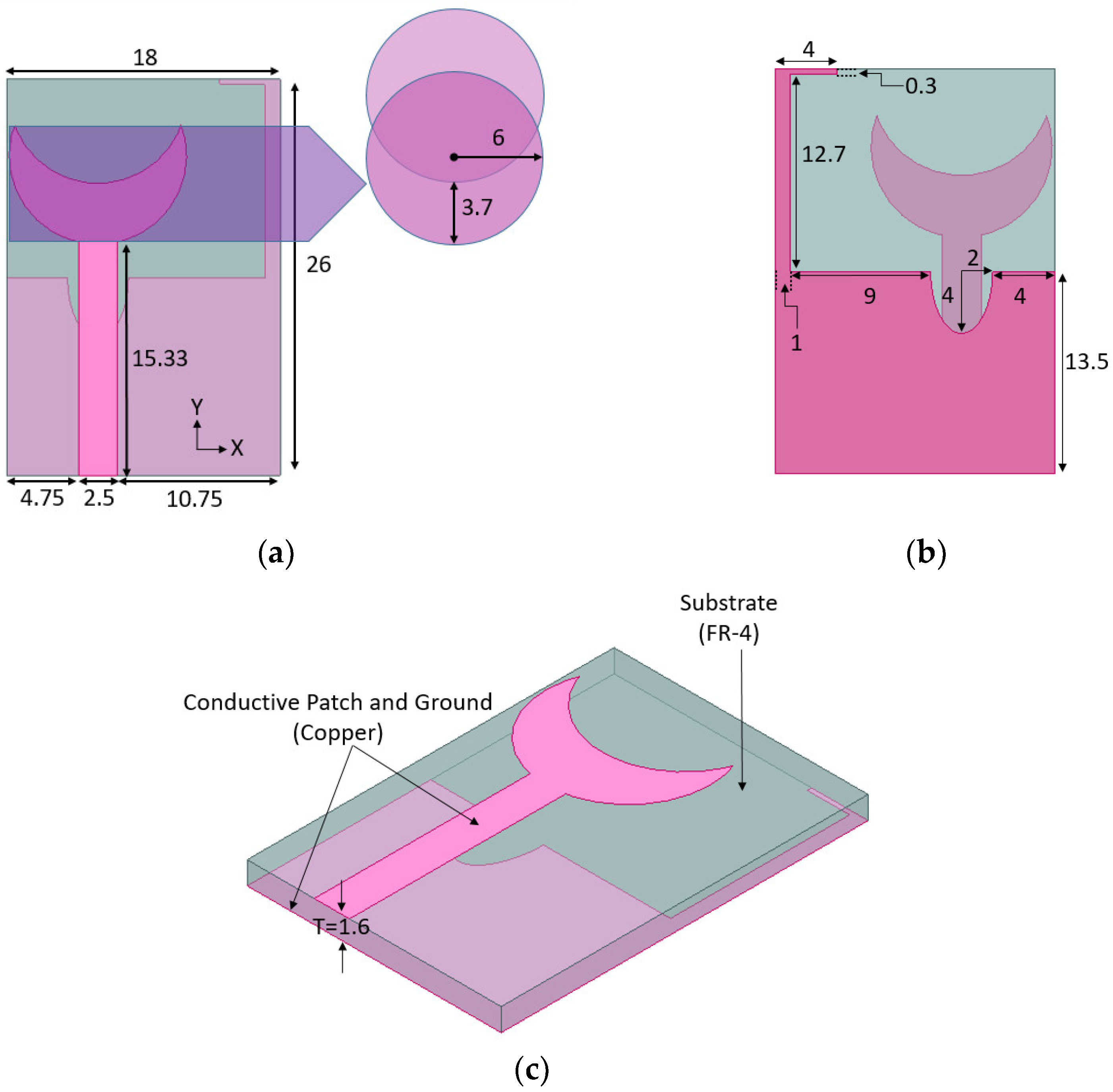
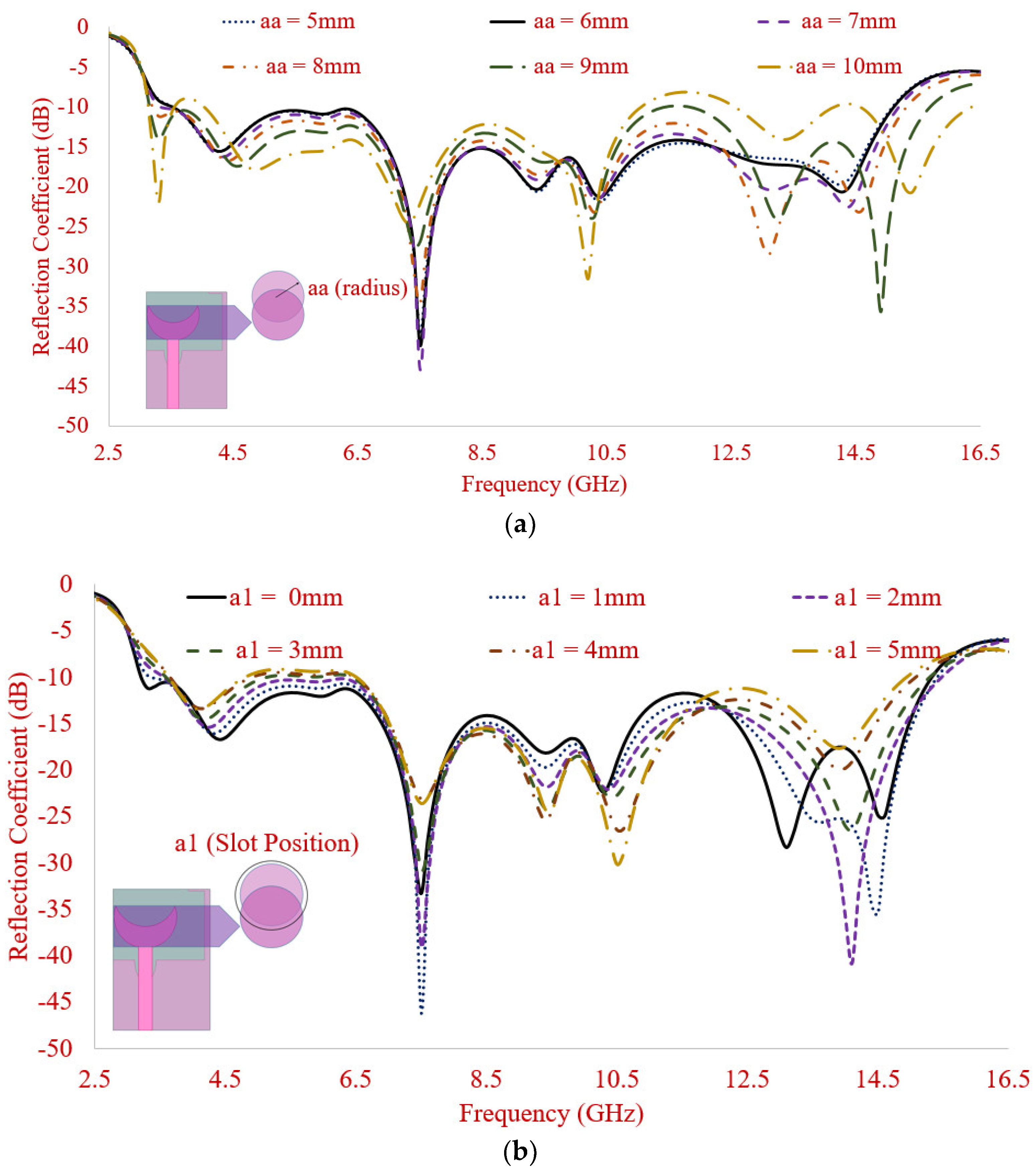
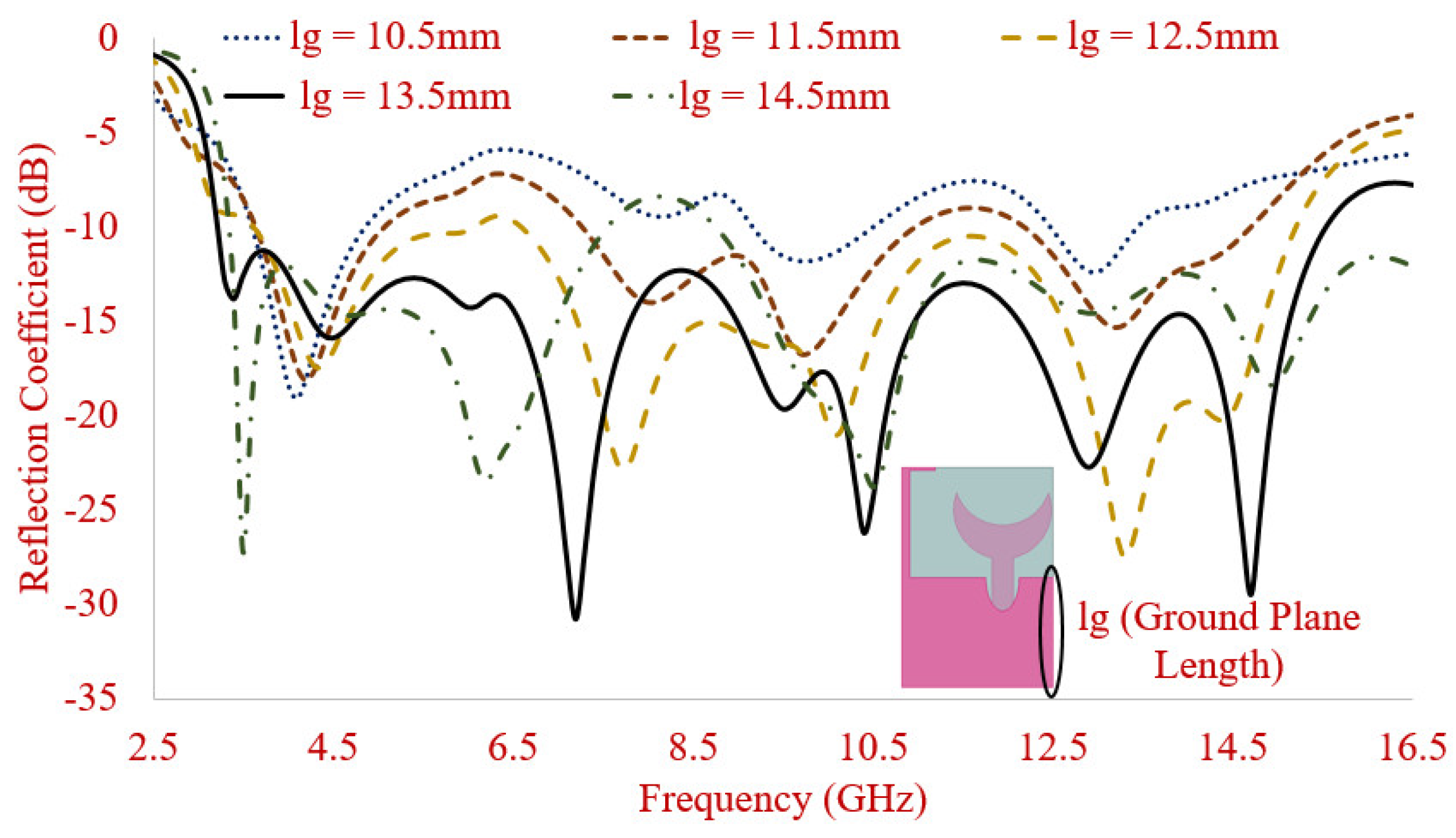
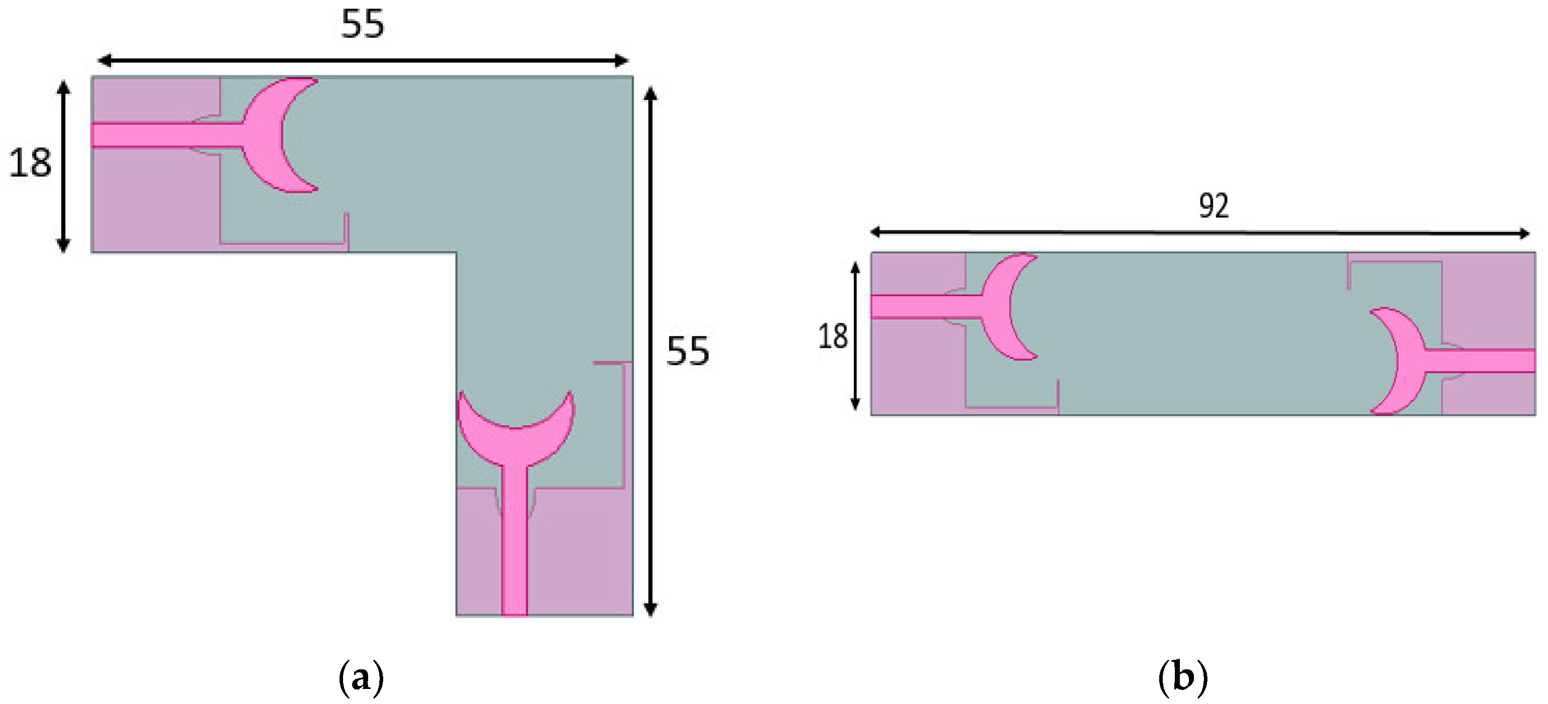
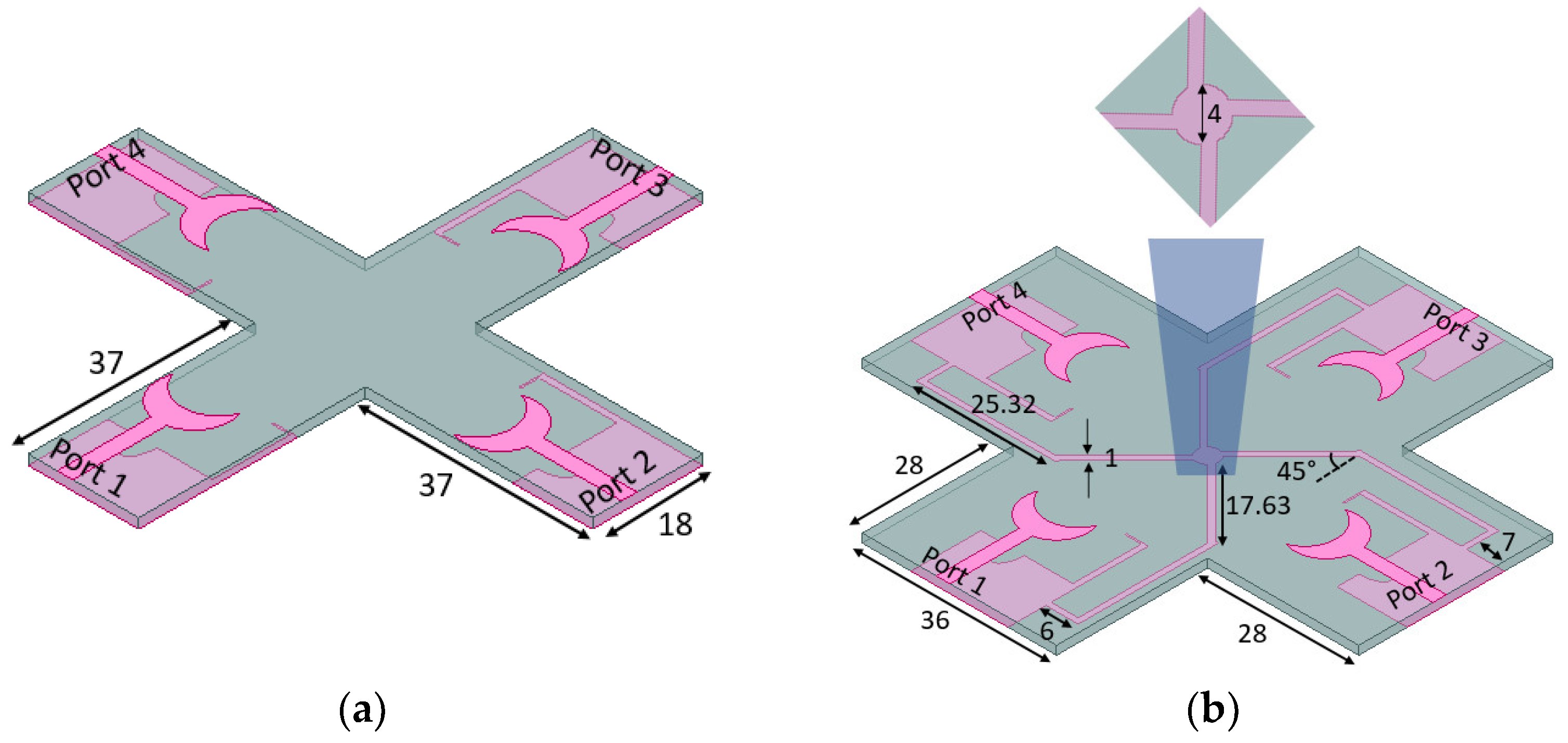
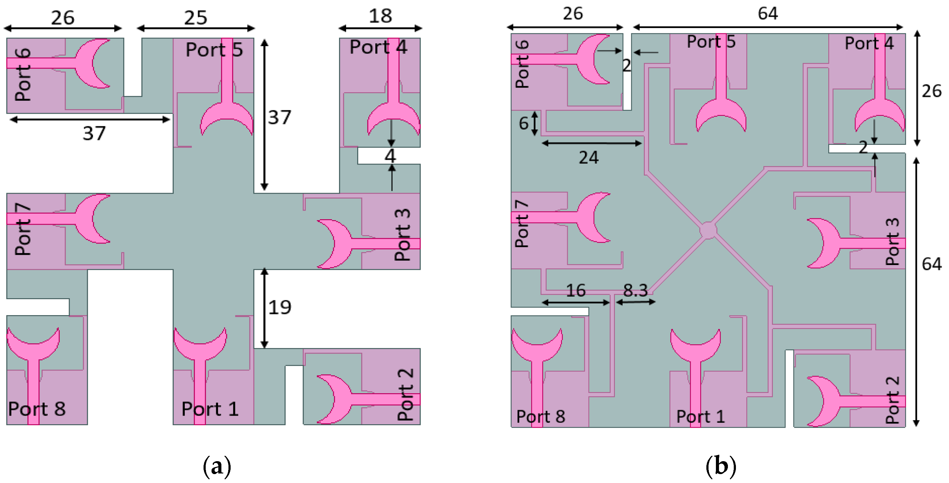
2. Antenna Configuration and Parametric Study

The antenna geometry (top and bottom) of a single element that is a part of a 4-element antenna is visible in Figure 1a,b. A circular arc-shaped structure on the top and a modified ground plane on the backside is simulated over the FR4 (Flame Retardant-4) substrate. The modified ground plane consists of an inverted L strip and semi-ellipse slot over the partial ground. The perspective view of the antenna as shown in Figure 1c shows the conductive part (patch and ground) printed over the substrate of a thickness (T) 1.6 mm.
The antenna is evaluated to check the effect on the reflection coefficient by varying the radius and position of the upper circle, as shown in Figure 2a,b. The variation of the upper circle radius (aa) (Figure 2a) affects the reflection coefficient levels majorly near the lower and upper part of the frequency band; however, the middle region is slightly affected. The value of the upper circular radius (aa) is chosen as 6 mm for wider bandwidth between the bands spanning from the semi-ellipse slot in terms of minor and major axis.
The optimized value of the upper circle position helps in attaining the required reflection coefficient levels while achieving the wide impedance bandwidth. The variation in the position of the upper circle will ultimately increase or decrease the arc formed over the lower circle since the upper circle is subtracted from the lower one. The optimized position of the upper circle before subtracting it from the lower circle is selected as 0 mm.
By variation of the ground plane length as shown in Figure 3, it is observed that the impedance bandwidth significantly increases. The reflection coefficient of the resonating peaks is also affected. By increasing the length of the conductive region of the ground plane, the impedance bandwidth increases. The value of ground plane length is chosen as 13.5 mm for attaining the best performance.
Figure 4 shows the top and back view of the basic antenna prototype fabricated on economical FR4 substrate (thickness, εr and tan (δ) of 1.524 mm, 4.5, and 0.002, respectively).
The basic element is used for simulating a dual-element, quad-element, and eight-element UWB antenna. First, the single element is duplicated in the vertical and horizontal positions, and S parameters are analyzed. The element at port 2 is rotated in an anticlockwise direction concerning port 1 along the horizontal axis in case 1 (Figure 5a) while in case 2, the element is mirrored along the vertical axis (Figure 5b).
Four element MIMO design is realized by arranging the single element to form a plus-shaped structure. Orthogonal, as well as spatial diversity, along with separate ground is first attained as shown in Figure 6a. Since the applicability of the MIMO antenna with separate ground is very limited, the plus-shaped structure is modified to accomplish a connected ground 4-element MIMO. The antenna elements are symmetrically and rotationally placed in a manner so that it occupies low surface area while achieving pattern diversity. Concerning the element at port 1, the element at port 2 is rotated in an anticlockwise direction along the horizontal axis while the element at port 3 is mirrored along the vertical axis, and lastly, the element at port 4 is rotated clockwise along the horizontal axis. The connection between the ground planes is carefully chosen for isolation level below −15 dB, which is visible in Figure 6b.
The current geometry helps the antenna to be inserted in the systems where perfect square-shaped space is unavailable and can be accommodated easily between the circuit elements. The fabricated front and back view of the UWB 4-element connected ground MIMO antenna is illustrated in Figure 7a,b which is analyzed for MIMO diversity performance in the next section.
Finally, an 8-element MIMO antenna is simulated as shown in Figure 8a,b where Figure 8a has a separate ground plane, and Figure 8b has connected ground. Additional four elements are added to the existing 4-element MIMO structure to achieve 8-element MIMO where two different cases are presented. Case 1 (Figure 8a) shows an 8-element structure without connected ground while in case 2 (Figure 8b), all the ground plane of all the elements is connected from the bottom side by carefully choosing the connecting lines.
The analysis in terms of S parameters, current distribution, radiation patterns, gain, efficiency, and MIMO diversity parameters are discussed in the next section for the configurations shown here.

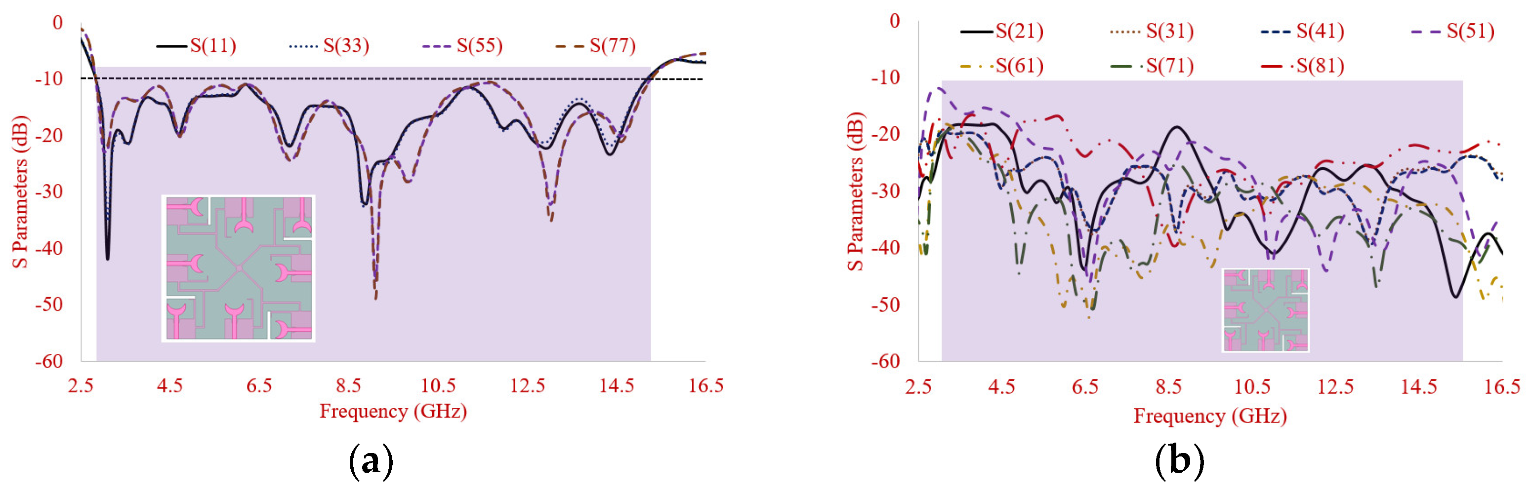
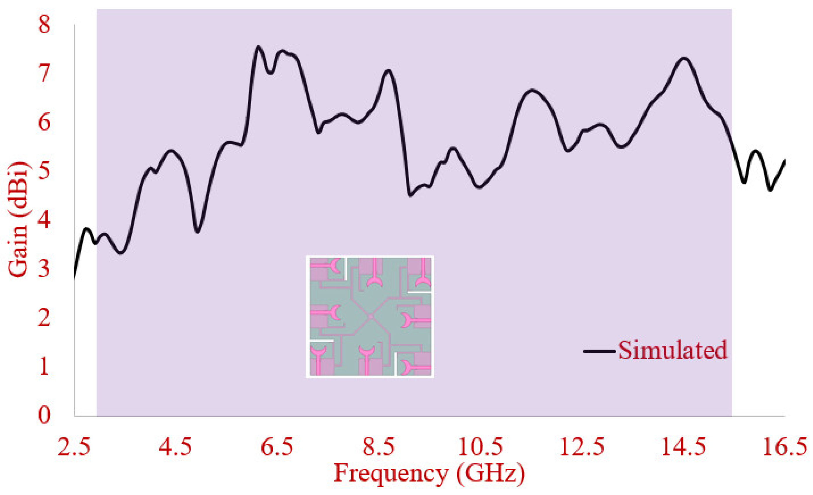
3. Results and Discussion

The reflection coefficient analysis of the basic element shows that the antenna covers an impedance bandwidth of (76.29%) 3.19–15.32 GHz where close correlation with simulated values is observed as illustrated in Figure 9.
The reflection coefficient of 2-element MIMO with separate ground is displayed in Figure 10 where apparent wide bandwidth and isolation >15 dB is observed for both the cases. The antenna resonates in the range of (134.70%) 3.01–15.43 GHz in case 1 while (134.38%) 3.01–15.34 GHz in case 2. The greater level of isolation is visible in the orthogonal arrangement of elements as compared to the elements arranged in a mirrored fashion along the vertical axis.
The simulated reflection coefficient of four-element MIMO with the separate and connected ground plane is displayed in Figure 11 where the antenna achieves IBW of (135.25%) 2.98–15.43 GHz in antenna with separate ground and (136.92%) 2.84–15.33 GHz in antenna with the connected ground plane. Isolation levels are greater in the case of an antenna with separate ground; however, the careful selection of strip lines for connecting the ground planes has helped the antenna in achieving the isolation levels >15 dB due to minimum inter-element coupling. The measured results for connected ground configuration (Figure 12) indicate that over a wide frequency band spanning from (136.69%) 2.86–15.21 GHz, the results are well-matched. Slight variation in reflection coefficient and isolations levels are due to fabrication tolerances and connector losses.
Figure 12 shows the experimental values of 4-element-connected ground S parameters. The orthogonal placement of elements (1–2, 23, 34, and 41) leads to isolation >16 dB between the proposed bands. The isolation value is >12 dB is achieved between the elements placed in a mirrored fashion. It increases above 15 dB after 3.8 GHz. The orthogonal element placement ensures good isolation due to lower mutual coupling and the orthogonally polarized patterns. Higher isolation among elements placed in a mirrored position is due to the spatial separation. A decent agreement between simulated and experimental values is visible from Figure 12.
To comprehend the isolation mechanism, the current distribution is observed at 3.1 GHz, 4.70 GHz, 6.90 GHz, and 9.5 GHz in 4-element-connected ground structure as depicted in Figure 13a–d, respectively. While carrying out the analysis, Port 1 is excited while other ports are terminated with a 50 Ω load. The field intensity at four resonant peaks suggests that isolation is very good with a negligible amount of coupling occurring between the inter-elements.
The experimental two-dimensional (2D) co/cross-polarization radiation patterns of the UWB connected ground MIMO antenna are depicted in Figure 14 by providing excitation at port 1 and keeping other ports terminated with matched load (50 Ω). The EH plane patterns are plotted at resonating frequencies of 3.10 GHz, 4.70 GHz, 6.90 GHz, and 9.50 GHz. The lower cross-polarization at resonant peaks for both planes can be observed.
Figure 15 depicts gain and efficiency plots by exciting port 1 and terminating other ports with impedance load (50 Ω). Average gain >4.5 dBi is observed for the bands of interest which closely matches with the measured gain values.
The S parameters of connected ground 8-element MIMO antenna are illustrated in Figure 16a–c. The simulated IBW of 8-port MIMO antenna is (137.47%)/2.84–15.3 as illustrated in (Figure 16a). Isolation of antenna concerning element 1 is depicted in Figure 16b where satisfactory isolation levels are observed having a value >15 dB, and the same is observed when isolation levels between other antenna elements are simulated (Figure 16c).
A simulated gain and efficiency plot by exciting port 1 and terminating other ports with impedance load (50 Ω) for an 8-port MIMO antenna is illustrated in Figure 17. Average gain >5.6 dBi is observed for the bands of interest.

4. MIMO Diversity Analysis

Antenna characterization for diversity performance is carried out using the method suggested in [31,32,33] as the antenna is proposed for its use in MIMO applications.

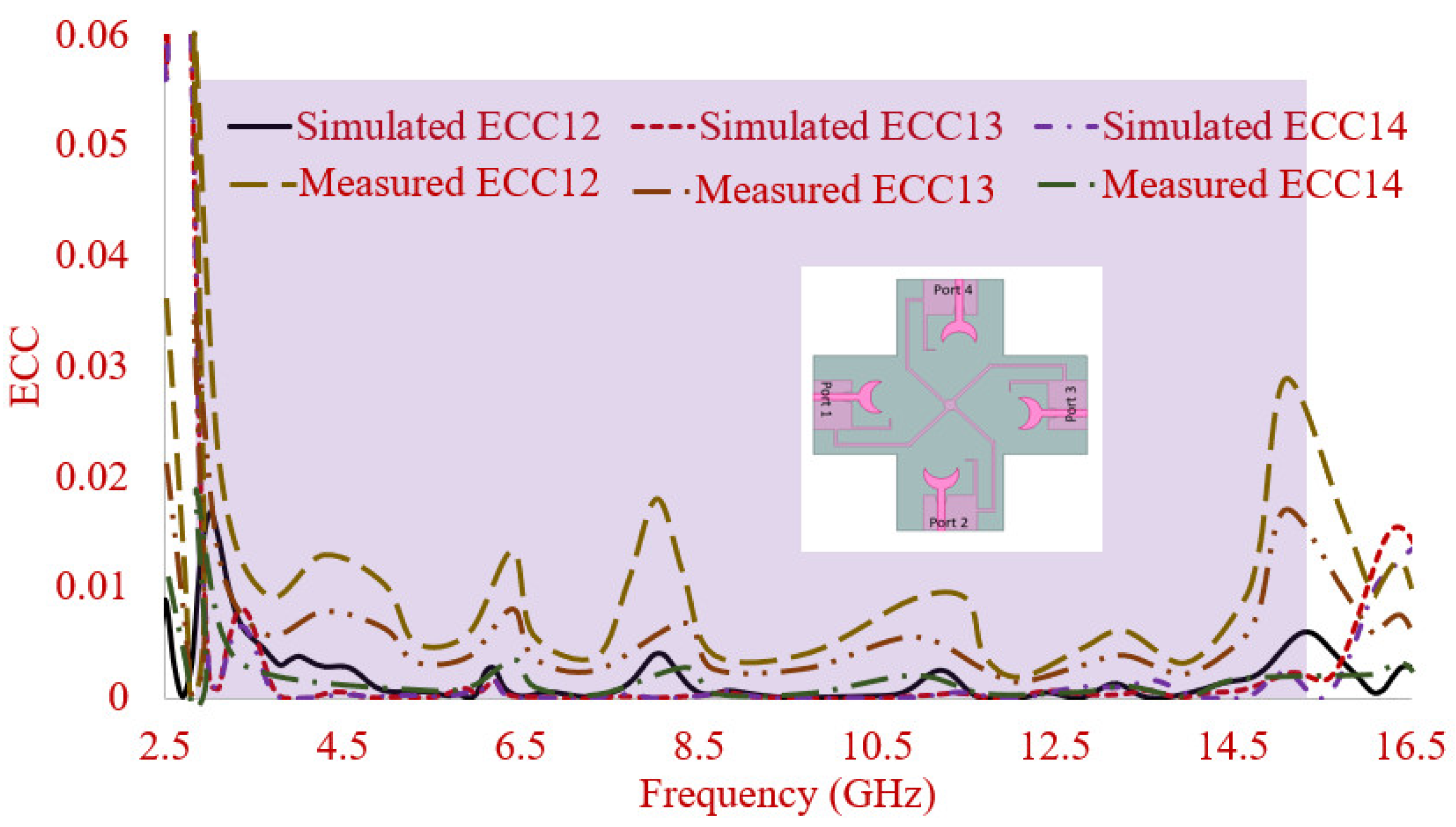
4.1. Envelope Correlation Coefficient (ECC)

ECC is a very essential parameter for measuring the diversity performance of MIMO antenna. It indicates how radiations of each antenna element are independent of each other in a practical environment where the signals of transmitter and receiver are multipath fading signals.
The ECC of two antenna elements is estimated by using the below equation and graphically illustrated in Figure 18.
ρ e = | 4 π [ F 1 ( θ , ) F 2   ( θ , ) ] d Ω | 4 π | F 1 ( θ , ) | 2 d Ω 4 π | F 2 ( θ , ) | 2 d Ω
where F i ( θ , ) is the three-dimensional field pattern of the antenna, when the ith port is excited. Ω is the solid angle measured over a sphere.
From Figure 18, it is noted that the ECC values (simulated and measured) of each antenna element (ECC 12, ECC 13, ECC 14) are very close to zero and less than 0.02. This validates that the MIMO antenna has uncorrelated far-field patterns and is suitable for UWB application.

4.2. Total Active Reflection Coefficient (TARC)

The TARC articulates the total incident power to the total outgoing power in presence of a multi-port antenna and is expressed in the below Equation (2) and shown in Figure 19.
T A R C = k = 1 N | b k | 2 k = 1 N | a k | 2
where in Equation (2), | a | and | b | are the excitation and scattering vector, respectively.
To verify the effect of TARC on impedance bandwidth, the proposed four-port MIMO antenna is integrated with an ideal phase shifter where a scan angle is varied from 30° to 180°. From Figure 18, it is visualized that for all scanning angles the TARC value lies below −10 dB confirming that all the delivered power is accepted by another antenna element without affecting the impedance bandwidth of the proposed four-port MIMO antenna. Therefore, this also validated that the proposed four-port MIMO antenna is also an attractive applicant for integration with a phase shifter.

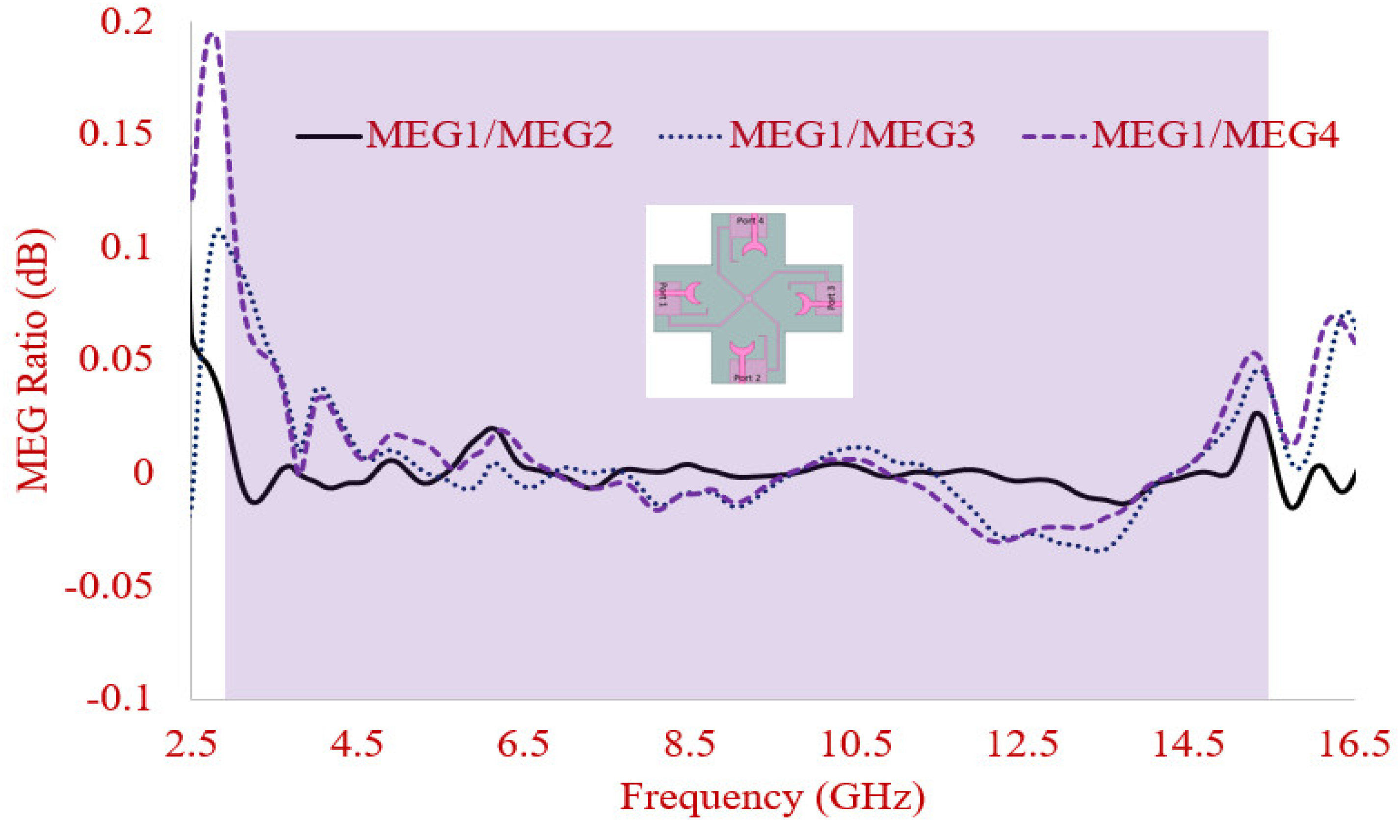
4.3. Mean Effective Gain (MEG)

The MEG is another essential diversity performance parameter for the characterization of MIMO antenna in wireless channels. MEG determines the ability of the antenna element to accept an electromagnetic signal in the presence of affluent multipath fading signals.
Therefore, Figure 20 illustrates the ratio of the mean received power to mean incident power of antenna elements. Each MEG ratio closer to 0 dB throughout the operating bands confirms that each antenna element is a suitable candidate for UWB MIMO applications.

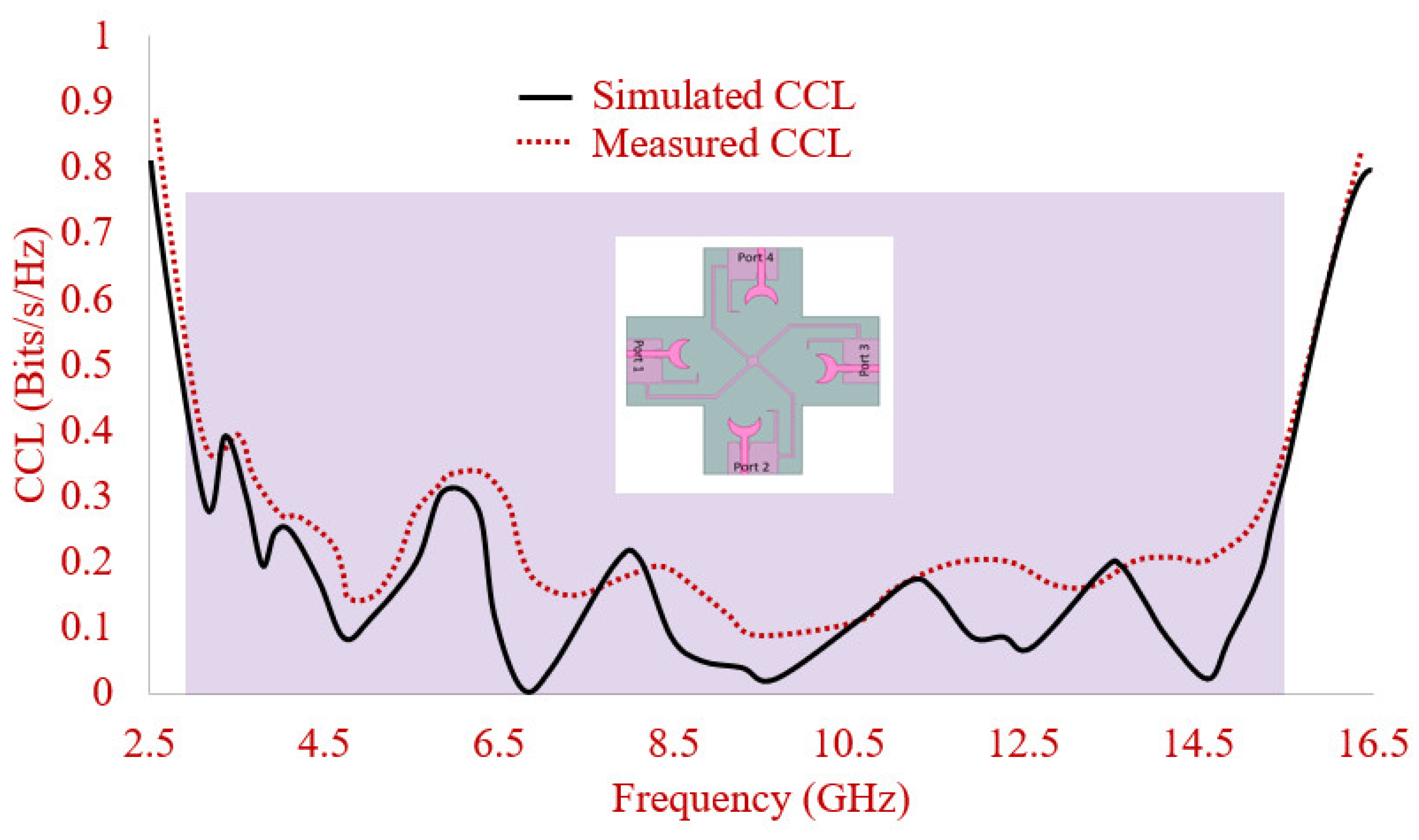
4.4. Channel Capacity Loss (CCL)

To achieve high data transmission, the minimum acceptable level of CCL is 0.5 bits/s/Hz. The CCL is calculated using Equation (3) and shown in Figure 21. The CCL values are as low as 0.4 bits/s/Hz which is well within the requirement set by the industry and matches well with the experimental values.

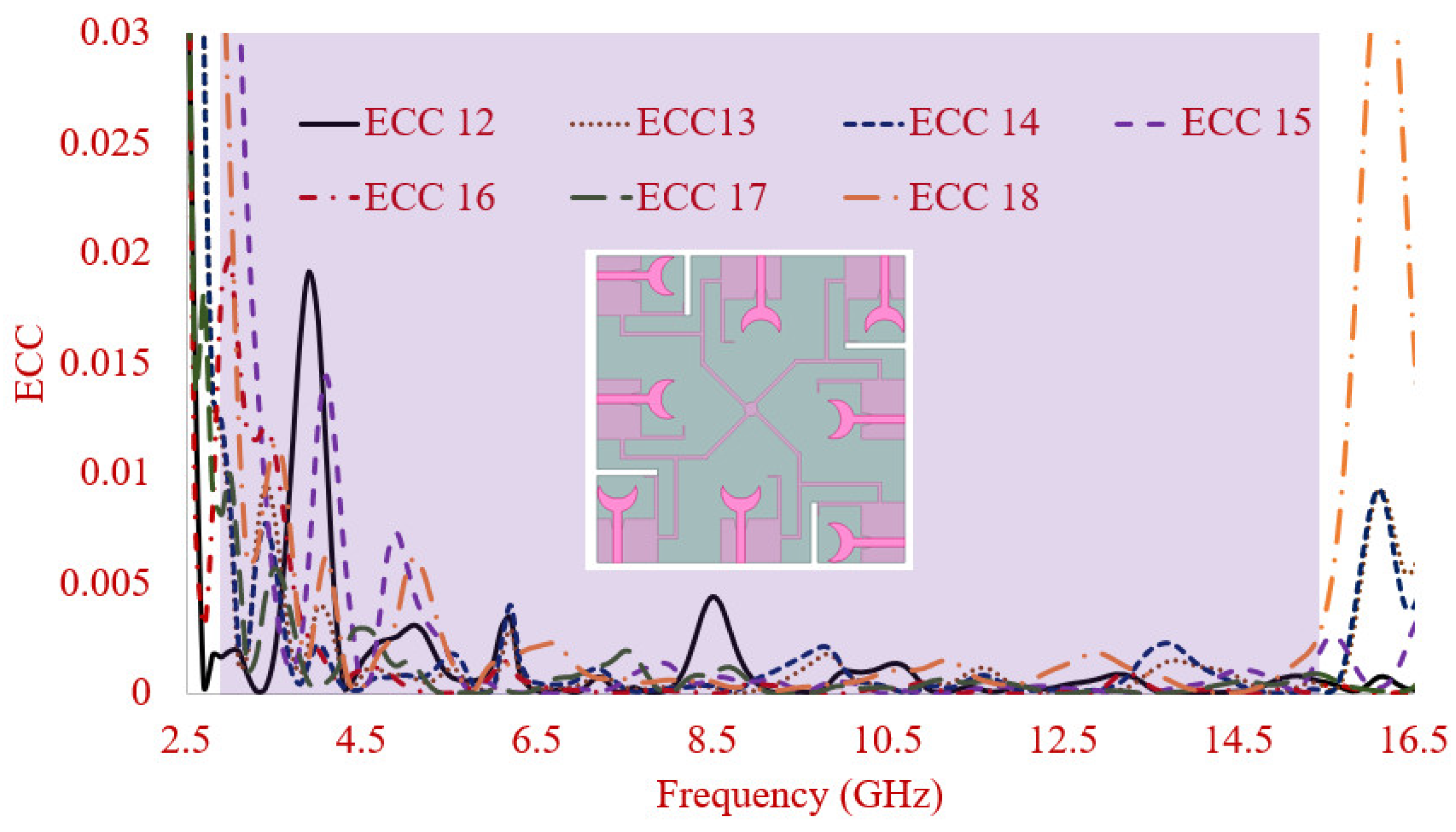
4.5. ECC of 8-Element-Connected Ground MIMO Antenna

From Figure 22, it is noted that the simulated ECC values of each antenna element (ECC 12, ECC 13, ECC 14, ECC 15, ECC 16, ECC 17, and ECC 18) are very close to zero and less than 0.02. This validates that the MIMO antenna has uncorrelated far-field patterns.

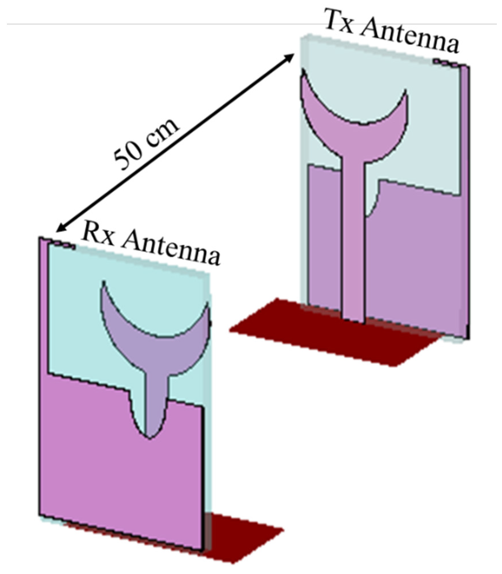
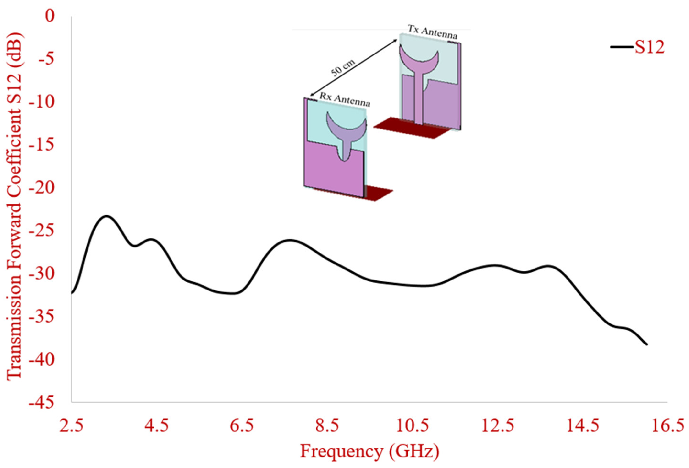
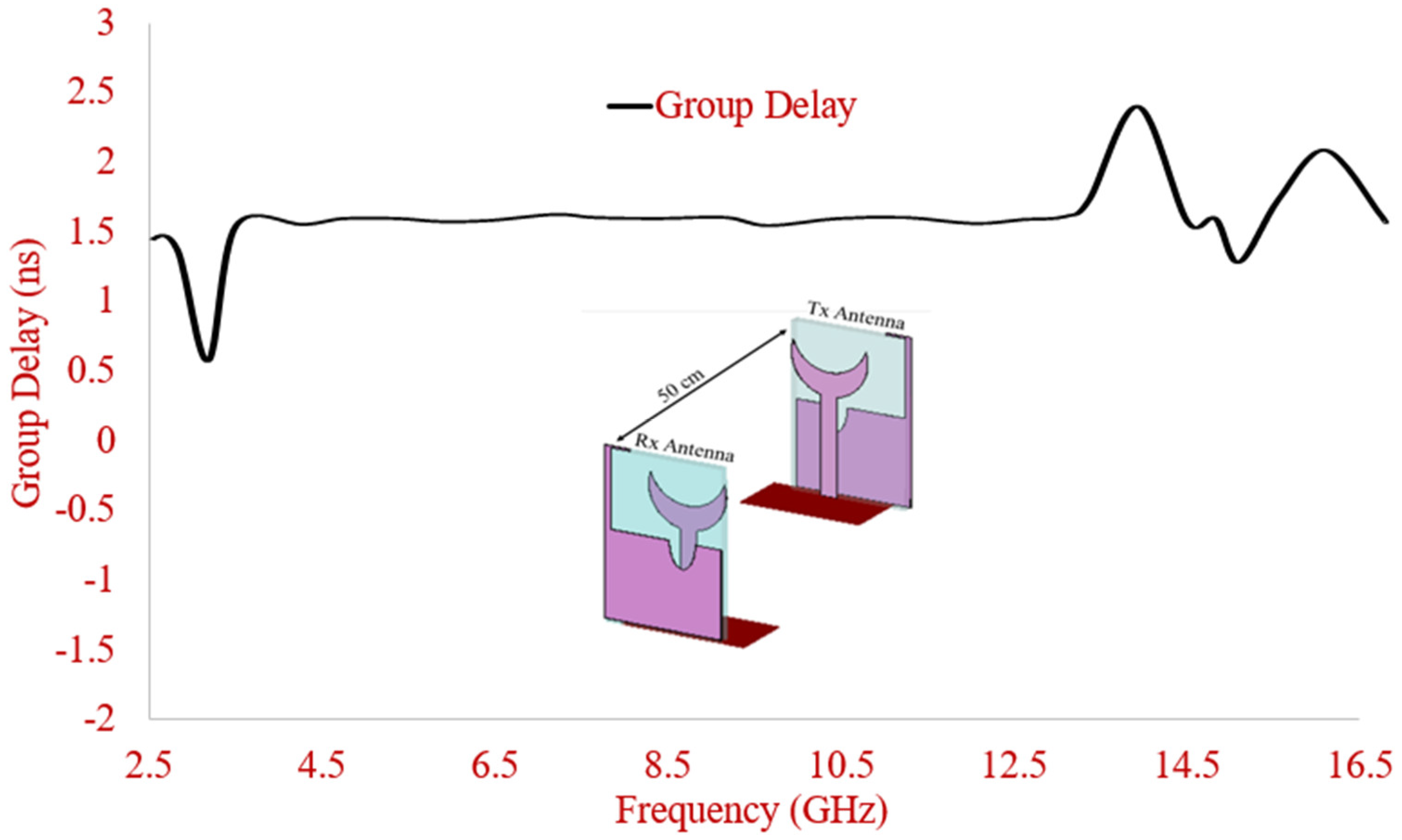
5. Time Domain Performance Analysis of the Proposed Antenna

In order to illustrate the time domain performance of the antenna, the time domain characteristics including forward transmission (S21) coefficient and group delay are investigated.
Figure 23 shows the experimental set-up that uses twin antennas, where one is acting as a transmitter (Tx) and another as receiver (Rx). These antennas are placed face-to-face at a distance of 50 cm which is five times the wavelength of lower operating frequency (around 3.00 GHz) in order to create far field atmosphere. Twin antennas are excited by using 5th order Gaussian pulse by using following equation (3):
x ( t ) = A ( 15 t 2 π σ 7 + 10 t 3 2 π σ 9 t 5 2 π σ 11 ) x exp ( t 2 2 σ 2 )
where in (3), ‘t’ is time, ‘A’ is amplitude, ‘σ’ is spread of Gaussian pulse.
In order to check the time domain response of the proposed antenna, the transmission coefficient (S21) of experimental set-up was simulated and shown in Figure 24. It is inspected that, proposed antenna exhibits the magnitude of the transmission coefficient (S21) below −25 dB over the entire operating bands.
Figure 25 shows the simulated group delay response of experimental set-up. It is observed that the group delay remains stable around 1.5 ns in operating bands of the proposed antenna.
Through the investigation of the time domain behavior of the proposed antenna, it can be concluded that the proposed antenna has linear transmission characteristics with lower transmission coefficient and stable group delay across the operating band’s interest. This confirms the applicability of the proposed antenna for UWB operations employed in wireless devices.
Table 1 shows the comparison of the proposed 4/8-element UWB antenna with other UWB MIMO antennas. The proposed 4/8-element antenna exhibits low profile as compared to most of the 8-port MIMO antennas, high IBW, isolation >15 dB without using any complex isolation or decoupling techniques, high gain as compared to all the existing state of Arts, and permissible MIMO diversity performance that makes the antenna commercially viable for portable UWB applications.

6. Conclusions

A four-element connected ground UWB-MIMO antenna with modified substrate geometry, and the defected ground is presented in this article. The low profile of the antenna is achieved using substrate shape which is different than the conventional square shape. The key parameters of the 4-element antenna are analyzed using simulation and experiment in terms of |S11|, radiation patterns, isolation, gain, and MIMO diversity parameters. A decent agreement is observed between the results. Connected ground helps the MIMO antenna for its use in commercial applications moreover defected structure with inverted L-shaped strip, and slotted semi ellipse at the ground plane helped in accomplishing the wideband performance. Isolation between elements >16 dB is achieved by orthogonally placing the antenna elements. The proposed low profile 4-elements UWB-MIMO antenna structure achieves wide IBW, stable gain, omnidirectional patterns, higher isolation, and decent diversity properties. The extended connected ground 8-element MIMO antenna also illustrated wide IBW, satisfactory isolation levels, and ECC that makes it a good candidate for portable UWB-MIMO systems.

Author Contributions

Conceptualization, T.A., A.D. and I.E.; methodology, T.A., N.A., J.K.; software, T.A., A.D.; validation, i.e., C.Z., and N.A.; formal analysis, A.D.; investigation, T.A., i.e., J.K.; resources, J.R., C.Z.; writing—original draft preparation, T.A., A.D.; writing—review and editing, i.e., R.A.-A., N.A.; visualization, J.K., C.Z.; supervision, R.A.-A.; project administration, J.R.; funding acquisition, I.E. All authors have read and agreed to the published version of the manuscript.

Funding

This work is funded by FCT/MCTES through national funds and when applicable co-funded EU funds under the project UIDB/50008/2020-UIDP/50008/2020.

Data Availability Statement

All data are included within manuscript.

Acknowledgments

This work is funded by FCT/MCTES through national funds and when applicable co-funded EU funds under the project UIDB/50008/2020-UIDP/50008/2020. Authors Issa Elfergani and Jonathan Rodriguez would like to acknowledge the POSITION-II project (ECSEL joint Undertaking under grant number Ecsel-7831132-Position-II-2017-IA).

Conflicts of Interest

The authors declare no conflict of interest.

References

  1. Federal Communications Commission. Federal Communications Commission Revision of Part 15 of the Commision’s Rules Regarding Ultra-Wideband Transmission System from 3.1 to 10.6 GHz; ET-Docket: Washington, DC, USA, 2002. [Google Scholar]
  2. Kaiser, T.; Zheng, F.; Dimitrov, E. An overview of ultrawide- band systems with MIMO. Proc. IEEE 2009, 97, 285–312. [Google Scholar] [CrossRef]
  3. Sharawi, M.S. Current misuses and future prospects for printed multiple input, multiple-output antenna systems [wireless corner]. IEEE Antennas Propag. Mag. 2017, 59, 162–170. [Google Scholar] [CrossRef]
  4. Watcharaphon, N.; Ruengwaree, A. Four-Port Rectangular Monopole Antenna for UWB-MIMO Applications. Prog. Electromagn. Res. 2020, 87, 19–38. [Google Scholar]
  5. Kulkarni, J.; Desai, A.; Sim, C.-Y.-D. Wideband four-port MIMO antenna array with high isolation for future wireless systems. Int. J. Electron. Commun. 2021, 128, 1–15. [Google Scholar] [CrossRef]
  6. Wu, W.; Yuan, B.; Wu, A. A quad-element UWB-MIMO antenna with band-notch and reduced mutual coupling based on EBG structures. Int. J. Antennas Propag. 2018. [CrossRef] [Green Version]
  7. Amin, F.; Saleem, R.; Shabbir, T.; Bilal, M.; Shafique, M.F. A compact quad-element UWB-MIMO antenna system with parasitic decoupling mechanism. Appl. Sci. 2019, 9, 2371. [Google Scholar] [CrossRef] [Green Version]
  8. Alam, T.; Thummaluru, S.R.; Chaudhary, R.K. Integration of MIMO and Cognitive Radio for Sub-6 GHz 5G Applications. IEEE Antennas Wirel. Propag. Lett. 2019, 18, 2021–2025. [Google Scholar] [CrossRef]
  9. Anitha, R.; Vinesh, P.V.; Prakash, K.C.; Mohanan, P.; Vasudevan, K. A compact quad element slotted ground wideband antenna for MIMO applications. IEEE Trans. Antennas Propag. 2016, 64, 4550–4553. [Google Scholar] [CrossRef]
  10. Mathur, R.; Dwari, S. Compact 4-Port MIMO/diversity antenna with low correlation for UWB application. Frequenz 2018, 72, 429–435. [Google Scholar] [CrossRef]
  11. Tripathi, S.; Mohan, A.; Yadav, S. A compact Koch fractal UWB MIMO antenna with WLAN band-rejection. IEEE Antennas Wirel. Propag. Lett. 2015, 14, 1565–1568. [Google Scholar] [CrossRef]
  12. Sipal, D.; Abegaonkar, M.; Koul, S. Easily extendable compact planar UWB MIMO antenna array. IEEE Antennas Wirel. Propag. Lett. 2017, 16, 2328–2331. [Google Scholar] [CrossRef]
  13. Ali, W.; Ibrahim, A.A. A compact double-sided MIMO antenna with an improved isolation for UWB applications. Int. J. Electron. Commun. 2017, 82, 7–13. [Google Scholar] [CrossRef]
  14. Rekha, V.; Pokkunuri, P.; Boddapati, T.; Madhav, P.; Yalavarthi, U. Dual Band Notched Orthogonal 4-Element MIMO Antenna with Isolation for UWB Applications. IEEE Access 2020, 8, 145871–145880. [Google Scholar] [CrossRef]
  15. Kayabasi, A.; Toktas, A.; Yigit, E.; Sabanci, K. Triangular quad-port multi-polarized UWB MIMO antenna with enhanced isolation using neutralization ring. Int. J. Electron. Commun. 2018, 85, 47–53. [Google Scholar] [CrossRef]
  16. Kumar, S.; Gwan, H.; Dong, H.; Wahab, M.; Hyun, C.; Kang, K. Multiple-input-multiple-output/diversity antenna with dual band-notched characteristics for ultra-wideband applications. Microw. Opt. Technol. Lett. 2020, 62, 336–345. [Google Scholar] [CrossRef]
  17. Hussain, R.; Sharawi, M.S.; Shamim, A. An Integrated Four-Element Slot-Based MIMO and a UWB Sensing Antenna System for CR Platforms. IEEE Trans. Antennas Propag. 2018, 66, 978–983. [Google Scholar] [CrossRef] [Green Version]
  18. Srivastava, G.; Mohan, A. Compact MIMO slot antenna for UWB applications. IEEE Antennas Wirel. Propag. Lett. 2015, 15, 1057–1060. [Google Scholar] [CrossRef]
  19. Sarkar, D.; Srivastava, K.V. A compact four-element MIMO/diversity antenna with enhanced band width. IEEE Antennas Wirel. Propag. Lett. 2017, 16, 2469–2472. [Google Scholar] [CrossRef]
  20. Tiwari, R.; Singh, P.; Kanaujia, B.; Srivastava, K. Neutralization technique based two and four port high isolation MIMO antennas for UWB communication. Int. J. Electron. Commun. 2019, 110, 152828. [Google Scholar] [CrossRef]
  21. Zamir, W.; Kumar, D. A compact 4× 4 MIMO antenna for UWB applications. Microw. Opt. Technol. Lett 2016, 58, 1433–1436. [Google Scholar]
  22. Li, W.; Yongqiang, H.; Grubb, P.; Shi, X.; Ray, C. Compact inkjet-printed flexible MIMO antenna for UWB applications. IEEE Access 2018, 6, 50290–50298. [Google Scholar] [CrossRef]
  23. Desai, A.; Upadhyaya, T.; Palandoken, M.; Gocen, C. Dual band transparent antenna for wireless MIMO system applications. Microw. Opt. Technol. Lett. 2019, 61, 1845–1856. [Google Scholar] [CrossRef]
  24. Desai, A.; Cong, B.; Patel, J.; Upadhyaya, T.; Byun, G.; Nguyen, T. Compact Wideband Four Element Optically Transparent MIMO Antenna for mm-Wave 5G Applications. IEEE Access 2020, 8, 194206–194217. [Google Scholar] [CrossRef]
  25. Sharawi, M.S. A 5-ghz 4/8-element MIMO antenna system for IEEE 802.11 ac devices. Microw. Opt. Technol. Lett. 2013, 55, 1589–1594. [Google Scholar] [CrossRef]
  26. Al-Hadi, A.A.; Ilvonen, J.; Valkonen, R.; Viikari, V. Eight-element antenna array for diversity and MIMO mobile terminal in LTE 3500 MHz band. Microw. Opt. Technol. Lett. 2014, 56, 1323–1327. [Google Scholar] [CrossRef]
  27. Saleem, R.; Bilal, M.; Bajwa, K.; Shafique, M. Eight-element uwb-mimo array with three distinct isolation mechanisms. Electron. Lett. 2015, 51, 311–313. [Google Scholar] [CrossRef]
  28. Li, M.; Xu, Z.; Ban, Y.; Sim, C.; Yu, Z. Eight-port orthogonally dual-polarised MIMO antennas using loop structures for 5g smartphone. IET Microw. Antennas Propag. 2017, 11, 1810–1816. [Google Scholar] [CrossRef]
  29. Mathur, R.; Dwari, S. 8-port multibeam planar uwb-mimo antenna with pattern and polarisation diversity. IET Microw. Antennas Propag 2019, 13, 2297–2302. [Google Scholar] [CrossRef]
  30. Zhang, X.; Li, Y.; Wang, W.; Shen, W. Ultra-wideband 8-port MIMO antenna array for 5g metal-frame smartphones. IEEE Access 2019, 7, 72273–72282. [Google Scholar] [CrossRef]
  31. Sharawi, M.S. Printed multi-band MIMO antenna systems and their performance metrics [wireless corner]. IEEE Antennas Propag. Mag. 2013, 55, 218–232. [Google Scholar] [CrossRef]
  32. Najam, A.I.; Duroc, Y.; Tedjini, S. Multiple-Input Multiple-Output Antennas for Ultra-Wideband Communications; IntechOpen: Rijeka, Croatia, 2012; Volume 10, pp. 209–236. [Google Scholar]
  33. Elfergani, I.T.E.; Hussaini, A.S.; Rodriguez, J.; Abd-Alhameed, R. Antenna Fundamentals for Legacy Mobile Applications and Beyond; Springer: Cham, Switzerland, 2017; pp. 1–659. [Google Scholar]
Figure 1. Single element antenna geometry (a) Top View (b) Bottom View (c) Perspective View (dimension in mm). Flame Retardant (FR).
Electronics 10 01476 g001
Figure 2. Parametric Variation of top circle (a) radius (aa) (b) position (a1).
Electronics 10 01476 g002
Figure 3. Parametric Variation of the ground plane (lg).a.
Electronics 10 01476 g003
Figure 4. Fabricated single element resonator (a) Front View (b) Back View.
Electronics 10 01476 g004
Figure 5. Resonator geometry of 2-element MIMO (a) case 1 (b) case 2 (dimension in mm).
Electronics 10 01476 g005
Figure 6. Resonator geometry of 4-element MIMO (a) Without common ground (b) with the common ground (dimension in mm).
Electronics 10 01476 g006
Figure 7. Fabricated 4-element Compact MIMO resonator (a) Front View (b) Back View (with the common ground).
Electronics 10 01476 g007
Figure 8. Resonator geometry of 8-element MIMO (a) Case 1, without common ground (b) Case 2, with common ground.
Electronics 10 01476 g008
Figure 9. Simulated and Measured Reflection Coefficient (dB) of Single Element UWB Antenna.
Electronics 10 01476 g009
Figure 10. Simulated S Parameters of 2-Element Compact MIMO Antenna (dB) (a) Case 1 (b) Case 2.
Electronics 10 01476 g010
Figure 11. Simulated S Parameters of 4-Element Compact MIMO Antenna (dB) (a) without common ground (b) with common ground.
Electronics 10 01476 g011
Figure 12. 4-Element Compact MIMO Antenna’s experimental values of S Parameters with common ground.
Electronics 10 01476 g012
Figure 13. The current distribution of 4-element compact MIMO antenna with the common ground at (a) 3.10 GHz (b) 4.70 GHz (c) 6.90 GHz (d) 9.50 GHz.
Electronics 10 01476 g013
Figure 14. Measured Co/Cross Pol pattern of 4-element compact MIMO antenna with the common ground at (a) 3.10 GHz (b) 4.70 GHz (c) 6.90 GHz (d) 9.50 GHz.
Electronics 10 01476 g014aElectronics 10 01476 g014b
Figure 15. Gain and Efficiency of the 4-element MIMO antenna with common ground.
Electronics 10 01476 g015
Figure 16. 8-Element Compact MIMO Antenna (dB) with common ground (a) Reflection coefficient (b) Isolation (antenna 1) (c) Isolation (Selected antennas).
Electronics 10 01476 g016aElectronics 10 01476 g016b
Figure 17. Gain and Efficiency of the 8-element MIMO antenna with common ground.
Electronics 10 01476 g017
Figure 18. ECC of 4-element compact MIMO with common ground.
Electronics 10 01476 g018
Figure 19. TARC of 4-element compact MIMO with common ground.
Electronics 10 01476 g019
Figure 20. MEG Ratio of 4-element compact MIMO with common ground.
Electronics 10 01476 g020
Figure 21. CCL of 4-element compact MIMO with common ground.
Electronics 10 01476 g021
Figure 22. ECC of 8-element compact MIMO with common ground.
Electronics 10 01476 g022
Figure 23. Test set-up for time domain analysis of the proposed antenna in CST MWS.
Electronics 10 01476 g023
Figure 24. Transmission coefficient of the proposed antenna.
Electronics 10 01476 g024
Figure 25. Group delay of the presented antenna.
Electronics 10 01476 g025
Table 1. Comparison of proposed 4/8 elements UWB MIMO antenna with other UWB MIMO antennas.
Ref. NoNo of ElementsSize
(mm2)
(At Lowest Freq)
Operating Band (GHz)Isolation (dB)Isolating ElementPeak Gain (dBi)ECC
[12]80.41 λ × 0.41 λ3.1–11>20Not Used4<0.01
[13]40.41 λ × 0.44 λ3.1–10.6>20Microstrip Multimode Resonator4<0.2
[15]40.77 λ × 0.77 λ3.1–17.3>13.5Neutralization Ring5.6<0.1
[16]40.67 λ × 0.67 λ2.8–13.3>18Rectangular Strip6<0.06
[17]40.15 λ × 0.3 λ0.75–7.65>12Not used3.2<0.24
[18]40.45 λ × 0.26 λ3.2–12>22Not used4<0.5
[20]40.56 λ × 0.39 λ(3.52–10.08)>22Neutralization Line2.91<0.04
[21]40.44 λ × 0.44 λ3.8–15>15Ground Stubs3<0.07
[26]81.65 λ × 0.82 λ4.95−5.05>10.5Spatial Diversity0.8--
[27]81.24 λ × 0.62 λ3.4−3.6>10CL-FSS, circular arcs, and four parallel strips----
[28]80.6 λ × 0.93 λ3−10.6>15square loop radiating strip with orthogonal polarisation----
[29]80.56 λ × 1.13 λ2.5−2.6>15Eight grounded Slits0.7<0.2
[30]80.75 λ × 1.5 λ3.3−6>11Not used--<0.1
[31]80.85 λ × 0.85 λ3−10.6>15Rectangular stub4.8<0.2
Proposed80.61 λ × 0.61 λ2.84–11
(effective BW)
>15Not Used7.2<0.02
Publisher’s Note: MDPI stays neutral with regard to jurisdictional claims in published maps and institutional affiliations.

