Abstract
Multiple access control (MAC) is crucial for devices to send data packets and harvest wireless energy in wireless powered Internet of Things (IoT) networks. A framed slotted ALOHA (FSA) protocol is employed in several practical networks. This paper studies an FSA-based MAC in a centralized wireless powered IoT network, including half-duplex devices and a full-duplex base station transmitting wireless energy in an intended direction. Under such a network, it is possible that a half-duplex device contends for a time slot to transmit a packet while the base station transmits wireless energy to the device in the same time slot, which causes vain charging and wastes the opportunity to charge other devices. To eliminate the vain charging, this paper designs a MAC in which a base station utilizes the information conveyed from devices in advance to arrange the charging order of devices. The novelty is to develop an algorithm to find a charging order of half-duplex devices instead of using full-duplex devices to eliminate the vain charging. Event-driven simulations are conducted to study the performance of the proposed MAC. Simulation results show that the proposed MAC produces better system performances than the system not eliminating the vain charging. In summary, the application of the proposed MAC yields the benefits of higher throughput and lower packet loss.
1. Introduction
In Internet of Things (IoT) networks, various sensors, actuators and smart devices automatically communicate with each other, which can provide diverse and extensive IoT services and applications, for examples, Industry 4.0, smart grid, smart home, smart cities, smart transportation, and smart healthcare etc., some of the surveys in IoT services and applications can be found in [1,2,3]. Since IoT devices are usually low-power and stand-alone devices, it is crucial to replenish the energy of the IoT devices and prolong the operation time of IoT networks. Therefore, a number of technologies, such as solar, kinetic, thermal, and wireless power transfer, and so on, are developed [4]. Among the current energy harvesting technologies, radio frequency (RF) energy harvesting is one promising solution to supply energy to IoT devices in a convenient and cost-effective manner. In RF energy harvesting, a device harvests energy from an RF energy signal transmitted from a base station (also called a power transmitter or access point). There are many studies in RF energy harvesting; some of the surveys in RF energy harvesting are in [5,6,7,8,9].
More devices would lead to more requirements for radio spectrum access. There are a number of ways to provide more spectrum access for IoT devices in a limited radio resource. One possible way is full-duplex communication, which is a promising technology to increase spectrum efficiency at the expense of increased hardware complexity and energy consumption [10]. As a base station is equipped with the module of full-duplex communication, the base station could send and receive on a channel at the same time. That is, a base station could send an RF charging signal and receive information simultaneously. In [11,12], a base station receives information and broadcasts RF charging signal simultaneously, and devices merely work in a half-duplex mode due to the reason of low-cost and easy implementation. Then, devices attempting to transmit cannot harvest RF energy in a time slot; however, those devices not sending information could harvest RF energy in the time slot. In [11], a device harvests wireless energy from those time slots in which the device does not transmit. In [12], each device continuously harvests wireless energy from the base station until it transmits data in its dedicated slot. Works in [11,12] assume that each device is allocated a dedicated time slot to send data; thus, there is no discussion on the time slot contention problem between devices.
A number of papers study RF energy harvesting and data transmission in contention-based (or called random-access-based) multiple access control (MAC) protocols. In [13], a carrier sense multiple access with collision avoidance (CSMA/CA)-based MAC is presented to balance the charging time and communication time in order to improve the system performance. In [14], a fair polling-based MAC is proposed to use a device’s energy harvesting rate to adjust its contention probability. In [15,16,17,18], a number of papers study RF energy harvesting and data transmission in the architecture of framed slotted ALOHA (FSA) protocol, which is a slotted ALOHA variant and is employed in several practical systems, for examples, machine-type communication networks [19], radio frequency identification (RFID) [20], and low-power wide-area networks (LPWAN) [21,22]. Due to several benefits of simplicity, low delay for short packets, without sensing in devices and without requiring initial connection setup, etc., the FSA is suitable for devices in IoT [23,24] and has been restudied recently. This paper focuses on RF energy harvesting and data transmission in the FSA system. In the FSA, time is divided into frames, and each frame is divided into time slots. At the beginning of a frame, each device having a packet to send selects a time slot in the frame randomly and contends for the time slot. If the device does not receive an acknowledgment from a base station, the device attempts to send in the next frame. In [15], a base station utilizes idle time slots to transmit RF energy. The base station detects whether a signal appears at the beginning of a time slot. If there is no signal, the base station sends an RF charging signal to all the devices in the coverage of the base station; otherwise, the base station receives and decodes the signal in the time slot. In [16], a time slot is divided into two phases. In the first phase, a base station broadcasts an RF charging signal to devices. The devices harvest the RF energy and store the energy in its battery. In the second phase, devices contend for slots to send data. The paper presents a proportionally fair resource allocation and determines (i) the optimal transmission power of base stations and (ii) the optimal duration of the two phases. In [17], a base station is equipped with successive interference cancellation, which can decode multiple transmissions; in the paper, a frame is divided into two parts. The first part is used for a base station to send an RF charging signal to charge devices equipped with batteries; the second part is further divided into time slots that are used to transmit data. Authors present distributed Q-learning-based channel access strategies to determine the transmission power of devices. The paper assumes that there is a saturated data buffer in each device, which implies that a device always has a data packet to transmit. In [15,16,17], a base station and devices work in a half-duplex mode. Therefore, as a base station receives data transmission, the base station cannot transmit. Moreover, the base station transmits RF energy in an omnidirectional manner. In [18], a base station works in full-duplex communication and transmits RF energy in an omnidirectional manner.
Instead of wireless power transfer in an omnidirectional manner (i.e., broadcasting RF charging signal), directional wireless power transfer [25,26,27,28,29,30] is used to increase the power intensity in the intended direction, which replenishes the energy of devices in superior energy transfer efficiency and reduces the energy waste of a base station. Since a base station equipped with directional antennas increases the energy density in an intended direction, the base station can have a longer energy transmission distance, which can be used in, for example, ecology monitoring in a forest where devices are far away from the base station [31]. Moreover, since the base station does not send energy in unintended directions, the base station can reduce its power consumption and prolong its operation time, which is especially important from the perspective of a stand-alone base station or a base station using green energy. In [29,30], directional energy transfer has been used to charge devices in IoT. In [26], data transmission and directional wireless power transfer are performed in different channels. In the channel of data transmission, devices send data in a time division multiple access (TDMA) manner. In [27], a device harvests energy in an energy harvesting slot and sends data in an energy consumption slot. An adaptively directional wireless power transfer is proposed to adapt an energy transfer strategy to the locations of devices and maximize the received power of devices. In [28], a time slot is divided into two parts. In the first part, a device sends data; in the second part, directional wireless power transfer is performed. In [26,27,28], the base station is half-duplex, and data transmission and energy harvesting are not studied in the FSA. To the best of our knowledge, there is no research on directional wireless power transfer in the FSA protocol.
This paper is the first work to study the FSA-based protocol on directional wireless energy transfer networks, including a full-duplex base station that can simultaneously send an RF charging signal and receive packets. The main difference between this work and the prior work [18] is that the base station in this work uses directional wireless energy transfer due to the superior energy transfer efficiency. There is an advantage of wireless power transfer in the FSA versus TDMA. Consider that a device sends data in successive frames. For a device assigned a dedicated slot in TDMA, the device cannot harvest energy in the frames since data transmission occupies the slot assigned to the device. However, for a device in the FSA, the device may harvest energy in the slots where the device does not send data because slots are sharable among devices. The main contributions of this paper are summarized as follows:
- This paper is the first work to identify the vain charging problem in an FSA-based directional wireless energy transfer network, which is not studied before. In the FSA-based networks, devices randomly select time slots to send packets, while a base station independently uses its charging policy to select devices to charge devices. It is possible that a device contends for a time slot while a base station uses the same time slot to send an RF charging signal to the device. As a half-duplex communication-based device contends for a time slot, the device cannot receive an RF charging signal; that is, the RF charging is in vain.
- To eliminate the vain charging, the objective of this paper is to design a MAC in which a base station utilizes the information conveyed from devices in advance to arrange the charging order of devices. The novelty is to develop an algorithm to find a charging order of half-duplex devices instead of using full-duplex devices to eliminate the vain charging.
- Event-driven simulations are conducted to study the performance of the proposed MAC. Simulation results show that the proposed MAC produces better system performances (in terms of packet dropping ratio and throughput) than the system not eliminating the vain charging. In summary, the proposed MAC effectively eliminates the vain charging discovered herein and significantly improves the system performance.
The rest of this paper is organized as follows: Section 2 describes the system architecture, time slot and frame structure. Then, the proposed directional RF charging MAC is introduced in Section 3. Simulation results and discussions are described in Section 4. Finally, some concluding remarks are presented in Section 5.
2. System Model
In this section, we first introduce the system architecture considered in this paper. Next, we describe time slots and frame structures used in the MAC under the system architecture.
2.1. System Architecture
Figure 1 illustrates the system architecture studied in this paper. There are devices in the coverage of a base station. The base station works in a full-duplex transmission mode; that is, the base station can send an RF charging signal to devices and receive data packets at the same time. In order to reduce the cost of devices, devices are half-duplex devices. That is, as a device transmits a data packet, the device cannot harvest an RF charging signal from a base station. Time is divided into time slots. The base station would omnidirectionally broadcast a message including system and control information to devices in a broadcast time slot. According to the received broadcast message, a device would use the message, the packets in its queue and the energy in its battery to enable a MAC procedure to contend for a time slot to send its packets. When the base station receives the data packets transmitted from the device, the data packet is further forwarded to other networks or a destination. In order to charge devices, a base station would use directional wireless power transfer to send an RF charging signal to a device. With the aid of RF localization of the devices [32], a base station obtains the precise positions of devices. Then, a base station transfers energy in a narrow range, which reduces energy consumption and interference. For simplicity, it is assumed that a base station sends an RF charging signal to one device in a time slot. The detailed procedure in the MAC will be described in Section 3.
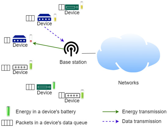
Figure 1.
System architecture.
A device is equipped with the module of RF energy harvesting to harvest an RF charging signal. Moreover, a device is equipped with a battery to store the harvested RF energy. The base station is assumed to be powered by a stable and unlimited power. Since an RF signal could carry information, receivers can retrieve information data and harvest RF energy at the same time; this technology is called “simultaneous wireless information and power transfer” (SWIPT) in [33,34,35,36,37]. The devices herein are equipped with the module of SWIPT. Therefore, as devices receive broadcast information, the devices could harvest RF energy.
2.2. Structures of Time Slots and Frames
Figure 2 displays the structures of time slots and frames. In this paper, time is first divided into frame times, and then a frame time is further divided into time slots. Time slots are classified into two types: downlink slots and uplink slots. In downlink slots, data packets are sent from a base station to devices. In uplink slots, devices send packets to the base station. The ratio of downlink slots to uplink slots is predetermined by a system operator considering traffic in a system. Since most traffic in the IoT is uplink traffic [38], a mere one downlink slot is included in a frame herein. The downlink slot is used as a broadcast slot. The broadcast time slot is at the beginning of each frame. During the broadcast slot time, a base station broadcasts a message including system and control information to devices, for example, frame synchronization, the number of slots in a frame, the acknowledgments in the previous frame. Next, consecutive time slots follow the broadcast time slot. The number of time slots in a frame is fixed, and the number is specified by system managers. The first time slot following the broadcast slot, as shown in Figure 2, is further divided into many mini-slots, each of which is allocated to one device in advance. A device uses its mini-slot to send its residual energy information to the base station.
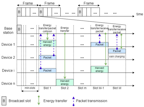
Figure 2.
Time slot and frame structures.
The mini-slot is used to merely send a device’s necessary information to the base station. Thus, the length of the mini-slot is short. The remaining time slots are used to carry data packets from a device to the base station. It is assumed that one data packet is sent in a time slot. A device uses a contention procedure to contend for a time slot to send a packet. In a broadcast slot, a base station broadcasts a message to devices; each device attempts to use SWIPT to harvest wireless energy in the broadcast slot. For each time slot following the group of mini-slots in a frame, a base station selects a device to send RF energy, and the device attempts to harvest the RF energy. In [39], a base station uses energy beamforming to directionally send wireless energy to a device in a time slot, to another device in the next slot, and so on; such an energy transfer scheme has good performance with lower complexity. This paper employs the technology that a base station sends wireless energy directionally to a device in a slot time; thus, it is assumed that an RF charging signal is sent to a device in a slot. Reference [40] provides a survey of energy beamforming and some descriptions of a sharp beam.
There are several examples of energy transfer and packet transmission in Figure 2. In slot 1, device 2 and device i contend for the same time slot, and the two packets collide with each other. The base station cannot receive packets successfully. In the slot M-1, mere one device, device 1, sends a data packet to the base station. Thus, the base station successfully receives the data packet. In slot 2, there is no device to send a packet. From slot 1 to slot M, a base station selects a device and sends an RF charging signal to the device. Note that in slot M, device 2 sends a data packet, and at the same time, the base station sends an RF charging signal to device 2; however, the device is half-duplex, and thus, the device cannot harvest the RF charging signal. This phenomenon is called “vain charging”. The proposed directional wireless charging MAC would avoid the vain charging, which will be described in detail in Section 3.
3. The Multiple Access Control with the Proposed Directional Wireless Charging Scheme
In this section, we describe a multiple access control used by base stations and devices in which the proposed directional wireless power transfer scheme is embedded. Since the proposed MAC is based on FSA, which core idea is random access, the MAC considers the mechanism that devices randomly select time slots to send packets. Other multiple access mechanisms, such as reservation schemes, are not the focus of this paper but could be studied in the future. We describe the MAC in the first two subsections: Section 3.1: data transmission and Section 3.2: energy sending and harvesting. In the last subsection, we use pseudocodes to represent the algorithms of the MAC procedures for devices and a base station and use an example to explain the mechanism of MAC, which eliminates the vain charging problem.
3.1. Data Transmission
A broadcast slot is positioned at the beginning of a frame. In the broadcast time slot, a device receives the broadcast information sent from a base station. A device would use the synchronization information in the broadcast information to synchronize with the base station. Following the broadcast time slot is a dedicated slot available for mini-slots. Each device sends its energy information in its corresponding mini-slot to the base station. There are M consecutive time slots following the dedicated time slot. If there is at least one packet in a device’s queue, the device will attempt to send a packet in the remaining M time slots. A device would first check the residual energy stored in its battery. If the residual energy is greater than a predetermined threshold, called stop transmission threshold, the device randomly selects one time slot among the M time slots and contends for the time slot to transmit a packet. If the device’s residual energy is less than or equal to the stop transmission threshold, the device will not contend for a time slot to send a packet. In order to avoid the vain charging, a device would in advance send its random selection in its corresponding mini-slot to the base station.
A base station listens to packets from devices. If there is merely one device transmitting a packet in a time slot, the base station receives the packet. Then, the base station replies an acknowledgment message to the device in the next broadcast slot. If there are two or more devices transmitting packets in a time slot, the packets will collide with each other. Then, the base station receives corrupted packets. The base station would not send an acknowledgment message. Those devices sending corrupted packets would attempt to re-send the same data packets with a permission probability p, where , in the next frame. Such an attempt of packet retransmission would be repeated until the delay of the packet exceeds a predetermined delay deadline. When the packet delay is greater than the delay deadline, the packet is dropped.
3.2. RF Energy Sending and Harvesting
In this subsection, we describe the RF energy transfer between a base station and devices.
3.2.1. RF Energy Sending
In a broadcast slot, a base station omnidirectionally sends an RF signal carrying broadcast messages. Except in the broadcast time slot and the dedicated slot for mini-slots, a base station would send an RF charging signal to charge one device in a time slot; thus, a base station should determine which device is selected to be charged. The selection procedure is as follows: During the dedicated slot time for mini-slots, a base station would receive (i) the information of the residual energy of devices and (ii) the random selection of devices. The random selection of a device is the time slot that a device randomly selects at the beginning of the dedicated slot. The base station collects the information of the residual energy and random selection and maintains a table recording the information. At the beginning of a time slot, the base station would first use the residual energy information in the table to select the device whose residual energy is the minimum in the table. If there is a tie, the base station randomly selects one device. Next, the base station checks whether or not the random selection of the selected device is the current time slot. If the random selection of the selected device is the current time slot, the base station gives up the selected device and attempts to select another device from the remaining devices in order to avoid the vain charging. The base station uses the above procedure to select another device whose residual energy is the minimum among the remaining devices until (i) the random selection of the selected device is not the current time slot or (ii) no device can be selected. If the random selection of the selected device is not the current time slot, the selected device is the device to which the base station sends an RF charging signal.
3.2.2. RF Energy Harvesting
A device harvests RF energy in a time slot only when the device does not send a packet in the time slot. It is possible for a device to harvest RF energy in a broadcast slot or other time slots (except in the dedicated slot for mini-slots). Since a base station broadcasts messages omnidirectionally in a broadcast time slot, each device can harvest RF energy in the broadcast time slot. If the battery of a device is not fully charged, the device can use the SWIPT technology to harvest RF energy in the broadcast time slot. For each of the time slots following the group of mini-slots in a frame, when a device does not send a packet in a time slot, the device can harvest RF energy in the time slot if (i) the base station transmits an RF charging signal to the device at the time slot and (ii) the battery of the device is not fully charged.
3.3. Pseudocodes and an Example
In this subsection, we first list the pseudocodes for devices and a base station as follows: Then, we give an example to explain the mechanism of the MAC to eliminate the vain charging.
Algorithm 1 shows the pseudocode for the MAC performed in a device Di. At the beginning of a frame, device Di uses the pseudocode to transmit packets and harvest energy. In the pseudocode, time slots that are available for devices to send packets are numbered by S1, S2, …, SM. As device Di has no packet to send, the random selection Ri of the device Di is assigned to be S0, which is indicated in line 5 in Algorithm 1. Algorithm 2 shows the pseudocode for the MAC used in a base station BS. At the beginning of a frame, BS uses the pseudocode to receive packets and transmit RF energy.
| Algorithm 1 Algorithm for Device Di | |
| 1 | Receive a broadcast packet in a broadcast slot |
| 2 | if (Di‘s residual energy > stop transmission threshold) and (at least one packet in Di‘s queue) then |
| 3 | Ri ← randomly select one slot from (S1, S2, …, SM) slots |
| 4 | else |
| 5 | Ri ← S0 |
| 6 | end |
| 7 | Send the information of Di‘s residual energy and random selection Ri in Di ‘s corresponding mini-slot |
| 8 | for each time slot Sj, j = 1, 2, ..., M |
| 9 | if (Sj is equal to Ri) then |
| 10 | Send a packet Pi in time slot Sj |
| 11 | else |
| 12 | if (RF charging signal is detected) then |
| 13 | Harvest RF energy |
| 14 | end |
| 15 | end |
| 16 | end |
| Algorithm 2 Algorithm for a Base Station BS | |
| 1 | Send a broadcast packet in a broadcast slot |
| 2 | Receive the information of devices’ residual energy and random selections in mini-slots |
| 3 | A ← the set of all devices |
| 4 | for each time slot Sj, j = 1, 2, …, M |
| 5 | do |
| 6 | Select a device Dm which residual energy is minimum from the set A |
| 7 | A←A—{Dm} |
| 8 | while (Dm ’s random selection is Sj and A is not empty) |
| 9 | if (Dm ’s random selection is not Sj) then |
| 10 | Send an RF charging signal to Dm while attempt to receive packets |
| 11 | else |
| 12 | Attempt to receive packets |
| 13 | end |
| 14 | end |
Table 1 shows an example of the information that is maintained in a base station. In this example, there are four devices, Di, where i = 1, 2, 3, 4, and four time slots Sj, where j = 1, 2, 3, 4. Table 1 displays the residual energy and the random selection of the four devices. In the beginning, i.e., in slot S1, a base station would use a table to select the device whose residual energy is the minimum; the selected device is device D2; however, the random selection of the device D2 is also slot S1. Then, if the base station sends an RF charging signal to device D2 in slot S1, the RF charging is in vain. Therefore, the base station gives up selecting device D2 and uses the table to select another device whose residual energy is the minimum among the remaining three devices. Then, the selected device is device D4. Since the random selection of the device D4 is slot S4, device D4 can harvest RF energy in slot S1. Therefore, the base station sends an RF charging signal to the device D4 in slot S1.

Table 1.
Information in a base station’s table.
4. Simulation Results and Discussions
In this section, we examine the performances of the proposed directional wireless power transfer scheme embedded in the MAC. We study three directional wireless power transfer schemes, which in turn are “full-duplex transmission without vain charging”, “full-duplex transmission”, and “half-duplex transmission”. The “full-duplex transmission without vain charging” is the proposed scheme herein. The “full-duplex transmission” herein refers to the full-duplex scheme not eliminating vain charging. The “half-duplex transmission” refers to a scheme in which a base station uses half-duplex communication to send an RF charging signal merely in an idle time slot. Event-driven simulations are conducted to study the performances of the three wireless charging schemes, which are, respectively, labeled as “FD w/o vain charging”, “FD”, and “HD” in Figure 3, Figure 4, Figure 5 and Figure 6. To fairly compare the performances of the three schemes, the same simulation scenario is applied in the three systems. In the future, the proposed MAC could be further implemented to study its performances in a real environment.
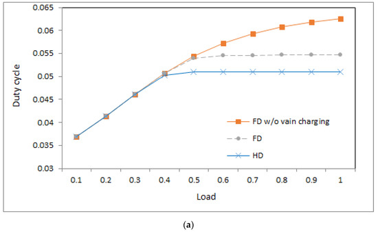
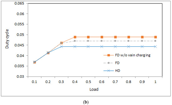
Figure 3.
Duty cycle: (a) ; (b) .
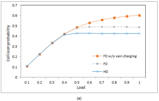
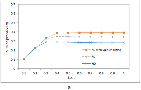
Figure 4.
Collision probability: (a) ; (b) .
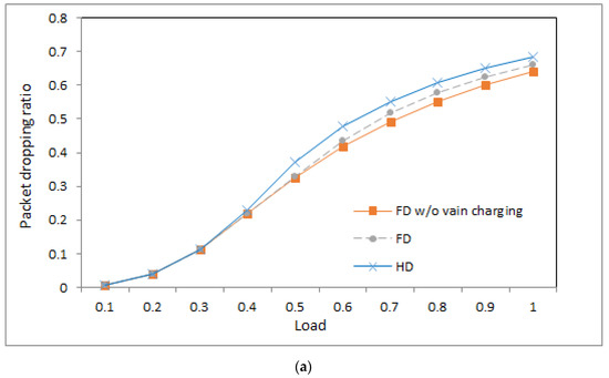
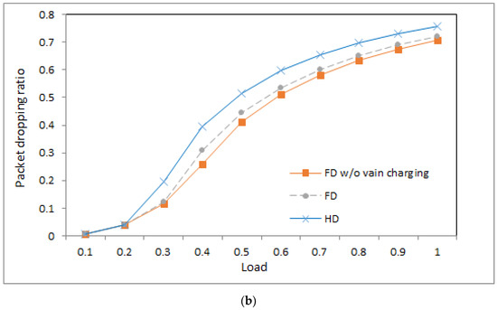
Figure 5.
Packet dropping ratio: (a) ; (b) .
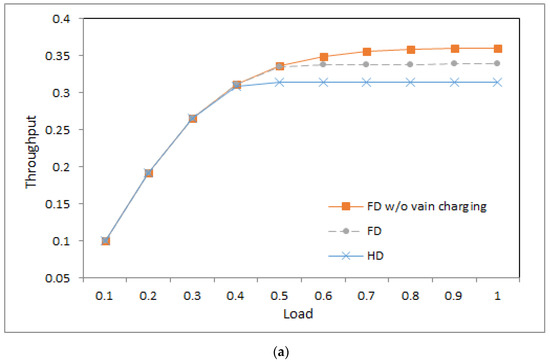
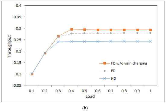
Figure 6.
Throughput: (a) ; (b) .
4.1. Performance Measures
The performance metrics used in this paper are duty cycle, collision probability, packet dropping ratio, and throughput, which are, respectively described as follows: For each device, the duty cycle is defined as the ratio of the total time spent in the sending and receiving states to the total operation time. In the simulation, the duty cycle is calculated as the ratio of a device’s mean number of slots in transmissions and receptions to the total time slots. The duty cycle could be used to observe the transmission and reception time of devices and the degree of power consumption of devices. The collision probability is defined for a data transmission attempt as the probability that a data transmission would collide with another data transmission. In the simulations, the mean collision probability is calculated as the ratio of the number of collisions to the total number of transmissions. The packet dropping ratio is defined for a data packet as the probability that a data packet is dropped; in the simulations, the packet dropping ratio is calculated as the ratio of the number of the dropped packets to the total packet arrivals. In order to observe the performances in different traffic loads, the mean data arrival is defined as the ratio of the offered traffic to the maximum traffic offered in time slots. The mean data arrival is the x-axis of Figure 3, Figure 4, Figure 5 and Figure 6. The throughput is defined as the successfully transmitted traffic offered in the simulation. As shown in Figure 6, the throughput is expressed as the successfully transmitted data arrival.
4.2. Simulation Parameters and Traffic Mode
An event-driven simulator is used to conduct extensive simulations [41] to compare the performances of the studied schemes. Table 2 lists the values of the system parameters used in the simulations. Packets are generated in devices. A Poisson process is used to generate packet arrivals. The Poisson process has been used in some use cases, for example, next-generation mobile network (NGMN) and event-triggered traffic [42]. In a Poisson process, the packet inter-arrival time is an exponential distribution. For simplicity, mere exponential packet inter-arrival time is considered herein. Thus, for all the three energy harvesting schemes in the simulations, packet inter-arrival time distribution is an exponential distribution. In a device, packets are transmitted in a first-in-first-out manner. A packet is transmitted at the beginning of a time slot. The size of a packet is predefined. A packet usually includes a fixed-length header field containing control information and a payload field containing data. As the size of a packet is longer, the ratio of the header to a packet is lower. Although a device can send one or more packets in a slot time, for simplicity and the reduction in the header overhead, a device herein sends one packet in a slot time.
Table 2.
System parameters.
Devices harvest RF energy at a certain harvesting rate. The energy harvesting rate would be about the order of microwatts, which is sufficient for the low-power devices in IoT [43,44]. According to the characteristics of devices, various devices have different requirements for power consumption. Therefore, for simplicity and ease of presentation, the RF energy harvested by a device in a time slot is denoted by . The means that the harvested RF energy provides times of the energy required to send a packet in a time slot. In the simulations, there are two RF energy harvesting rates in a time slot, 1 and 0.5, used in the three systems. Since devices also harvest RF energy in broadcast slots, the RF energy harvested in a broadcast slot is denoted by , which means that the harvested RF energy in a broadcast slot provides times of the energy required to send a packet in a time slot.
The event-driven simulation closely simulates the FSA procedure at a MAC level, which benefit is to easy to observe the relation between the performance measures and the FSA operation at a MAC-layer protocol concerned herein. Thus, the simulation uses a number to represent the RF energy harvesting rate in a time slot at a MAC level instead of using the detailed parameters of RF signals at a physical layer, which may be a deficiency from the viewpoint of a physical layer; however, the detailed physical parameters of RF signals applied to the FSA can be discussed in the future from the perspective of a cross-layer protocol between MAC and physical layers. The event-driven simulation has been used herein to yield the maximum throughput of slotted ALOHA in the condition of sufficient energy. The percentage of the difference between the yielded maximum throughput of 0.365 and the theoretical maximum throughput of e−1 ≈ 0.368 in [45] is less than one percent.
4.3. Duty Cycle
Figure 3a,b shows the duty cycles of the three systems under different loads when the value is 1 and 0.5, respectively. From the figures, we can observe a number of phenomena.
- First, in the light load, the three systems produce similar duty cycles because the energy of the devices in the three systems is sufficient to satisfy the transmission and reception in the light load.
- Second, in the middle and heavy loads, the system of base stations with half-duplex communication produces a lower duty cycle than the other two systems because the base station in the former system sends an RF charging signal merely in an idle time slot and then has a lower opportunity to charge devices than that in the latter two systems. The system with less energy satisfies fewer transmissions and receptions under middle and heavy loads, which yields a lower duty cycle.
- Third, for the two systems with full-duplex communication, the system without vain charging yields a higher duty cycle than that with vain charging in the middle and heavy loads. The reason is as follows: In the system without vain charging, devices have more energy to transmit and receive.
- Fourth, in the light load, the systems with different values of produce a similar duty cycle. The reason is as follows: Although lower implies longer charging time and devices have lower energy on average, the energy in devices is sufficient to transmit packets in the light load and then a similar duty cycle is yielded.
- Fifth, the system with a lower value of produces a lower duty cycle in the middle and heavy loads because lower implies longer charging time, and the devices have insufficient energy to transmit and receive in middle and heavy loads.
- Sixth, for the system without vain charging in Figure 3a, the duty cycle is increasing the load because sufficient energy is available for devices to send more traffic. For the remaining systems in Figure 3a,b, the duty cycle is increasing with the increasing load as the load is light. When the load is middle and heavy, the curves of the duty cycles in the remaining systems approach flat because the amount of energy in the devices restricts the time to transmit and receive.
4.4. Collision Probability
Figure 4a,b show the collision probabilities of the three systems under different loads when the value is 1 and 0.5, respectively. The collision probabilities in the figures are average collision probabilities. From the figures, we can observe the following phenomena.
- First, in the light load, the three systems produce similar collision probability because the energy of the devices in the three systems is sufficient to transmit packets. Thus, a similar number of data transmission yields similar collision probability.
- Second, under middle and heavy loads, the system with half-duplex communication produces lower collision probability than the other two systems. This is because the base station in the former system sends an RF charging signal merely in an idle time slot, and devices in the former system then have lower energy and opportunity to contend time slots, which yields lower collision probability.
- Third, for the two systems with full-duplex communication, the system without vain charging yields higher collision probability than that with vain charging in the middle and heavy loads. The reason is as follows: When vain charging is eliminated, devices have higher energy on average and have a higher opportunity to contend for time slots, which causes higher collision probability.
- Fourth, in the light load, the systems with different values of produce similar collision probability. The reason is as follows: Although lower implies longer charging time, the energy in devices is sufficient to contend for time slots to transmit packets in the light load.
- Fifth, the system with a lower value of produces lower collision probability in the middle and heavy loads because lower implies less harvested energy, which leads to fewer packet transmission attempts in the middle and heavy loads. Then, the opportunity to contend for time slots is lower, and then collision probability is also lower.
- Sixth, for the system without vain charging in Figure 4a, the collision probability is increasing with increasing load because sufficient energy is available for devices to contend time slots. For the remaining systems in Figure 4a,b, the collision probability is increasing with the increasing load as the load is light. When the load is middle and heavy, the curves of the collision probabilities in the remaining systems approach flat. This is because the amount of energy in the devices restricts the opportunity to contend for time slots, which limits the number of contentions and yields a flat collision probability.
4.5. Packet Dropping Ratio
Figure 5a,b show the packet dropping ratios of the three systems under different loads when the value is 1 and 0.5, respectively. From the figures, we can observe a number of phenomena.
- First, in the very light load, the three systems produce a similar packet dropping ratio because the devices in the three systems have a similar duty cycle and collision probability. The similar duty cycle implies that packets have a similar situation to be sent; a similar collision probability implies that packets have a similar probability of being collided. Therefore, in the systems, the situation that packets are not sent within a deadline is similar.
- Second, under middle and heavy loads, the system with half-duplex communication produces a higher packet dropping ratio than that with full-duplex communication. The reason is as follows: The base station using half-duplex communication merely sends RF charging signals in idle time slots, and thus, devices have lower energy. Then, more packets are not sent within a deadline, which yields a higher packet dropping ratio.
- Third, for the two systems with full-duplex communication, the system without vain charging yields a lower packet dropping ratio than that with vain charging in the middle and heavy loads. The reason is as follows: As vain charging is eliminated, devices would have higher energy on average and have a higher probability to send packets within a deadline, which causes a lower packet dropping ratio.
- Fourth, in the very light load, the systems with different values of produce a similar packet dropping ratio. This is because the systems have a similar duty cycle and collision probability in the light load, which implies that packets have a similar situation to be sent and have a similar probability of being collided. Thus, the systems have a similar packet dropping ratio.
- Fifth, with increasing load, packet dropping ratio is also increasing because more traffic packets would cause more serious collisions, and more collisions further prolong packet delay such that the opportunity of packet delay exceeding the delay deadline is increased.
4.6. Throughput
Figure 6a,b shows the throughput of the three systems at different loads as the value is 1 and 0.5, respectively. From the figures, we can observe a number of phenomena.
- First, in the light load, the three systems produce similar throughput because packets in the three systems suffer a similar packet dropping ratio, and then similar throughput is yielded.
- Second, under middle and heavy loads, the system with half-duplex communication produces lower throughput than the other two systems. This is because the half-duplex communication-based base station charges devices merely in idle time slots. Then, devices have less energy, and fewer packets are sent successfully.
- Third, under middle and heavy loads, the system without vain charging produces higher throughput than that with vain charging. This is because devices in the former system have more wireless charge opportunities than those in the latter system. Devices with higher energy have a higher opportunity to transmit packets successfully.
- Fourth, in the middle and heavy loads, the system with a lower value produces lower throughput than that with a higher value. This is because a lower value implies a longer charge time. Devices, on average, have less energy, and fewer packets are sent successfully.
- Fifth, throughput is increasing with the increasing load as the load is light. This is because more data packets are sent successfully. Under middle and heavy loads, the throughput curves approach flat because the amount of energy in the devices restricts successful packet transmission.
4.7. Discussion
In a large-scale IoT network, a large number of devices can be connected based on a hierarchical architecture [46,47]. Moreover, for a base station, in order to accommodate more devices, multiple radio channels can be employed. Devices are distributed to radio channels, each of which the proposed FSA-based MAC performs on.
A device should be allocated a dedicated mini-slot to send its residual energy and its random selection. Thus, the number of mini-slots restricts the number of devices in a frame. Let m denote the number of devices accommodated in a frame time. Let Ns denote the maximum number of mini-slots in a slot time. Then, the number of the dedicated slots required by the devices is equal to . The number of slots in a frame is equal to the ratio of a frame time Tf to a slot time Tl, i.e., Tf/Tl. From another viewpoint, the number of slots in a frame is the sum of (i) the number of downlink slots, Nb, (ii) the number of the dedicated slots for the mini-slots required by the devices, , and (iii) the number of uplink data slots, Nd. Thus, according to the total number of slots in a frame, we can obtain the following equation:
Solving Equation (1), we can obtain the inequality as follows:
The maximum number of devices in a frame, , is the maximum integer m satisfies Equation (2). Given devices are allowed to access slots every α frames, the maximum number of devices in a base station with Nc channels is .
5. Conclusions
This paper studies a centralized wireless powered communication network in which half-duplex communication-based devices are around a full-duplex communication-based base station. As directional wireless power transfer is applied in a time slot in the FSA that is widely deployed on many IoT networks, it is possible that a base station sends an RF charging signal to a device in a time slot while the device contends for the same time slot to transmit a packet, which causes that the RF charging is in vain and the opportunity to charge other devices is also wasted. To eliminate the vain charging, this paper designs a MAC in which a base station utilizes the information conveyed from devices in advance to arrange the charging order of devices. The novelty is to develop an algorithm to find a charging order of half-duplex devices instead of using full-duplex devices to eliminate the vain charging. Event-driven simulations are conducted to study the performances of the proposed MAC. Simulation results show that the proposed MAC produces better system performances (in terms of lower packet dropping ratio and higher throughput) than the system not eliminating the vain charging. In summary, the application of the proposed MAC yields the benefits of higher throughput and lower packet loss.
In the proposed MAC, with the increasing traffic load, the number of uplink data slots in a frame shall increase to transmit more packets. However, as the number of slots in a frame increases, the response of packet transmission is also increasing. Thus, the limitation of the MAC depends on the requirement of packet delay. For the traffic with a delay constraint, using more radio channels to distribute traffic is a possible way.
Author Contributions
Conceptualization, Y.-J.L. and S.-S.T.; data curation, Y.-J.L. and S.-S.T.; investigation, Y.-J.L. and S.-S.T.; methodology, Y.-J.L. and S.-S.T.; software, Y.-J.L. and S.-S.T.; supervision, Y.-J.L. and S.-S.T.; validation, Y.-J.L. and S.-S.T.; visualization, Y.-J.L. and S.-S.T.; writing—original draft, Y.-J.L. and S.-S.T.; writing—review and editing, Y.-J.L. and S.-S.T. All authors have read and agreed to the published version of the manuscript.
Funding
This research received no external funding.
Conflicts of Interest
The authors declare no conflict of interest.
References
- Nauman, A.; Qadri, Y.A.; Amjad, M.; Zikria, Y.B.; Afzal, M.K.; Kim, S.W. Multi-media Internet of Things: A comprehensive survey. IEEE Access 2020, 8, 8202–8250. [Google Scholar] [CrossRef]
- Puliafito, C.; Mingozzi, E.; Longo, F.; Puliafito, A.; Rana, O. Fog computing for the Internet of Things: A survey. ACM Trans. Internet Technol. 2019, 19, 1–41. [Google Scholar] [CrossRef]
- Lin, J.; Yu, W.; Zhang, N.; Yang, X.; Zhang, H.; Zhao, W. A survey on Internet of Things: Architecture, enabling technologies, security and privacy, and applications. IEEE Internet Things J. 2017, 4, 1125–1142. [Google Scholar] [CrossRef]
- Ma, D.; Lan, G.; Hassan, M.; Hu, W.; Das, S.K. Sensing, computing, and communications for energy harvesting IoTs: A survey. IEEE Commun. Surv. Tuts. 2020, 22, 1222–1250. [Google Scholar] [CrossRef]
- Cansiz, M.; Altinel, D.; Kurt, G.K. Efficiency in RF energy harvesting systems: A comprehensive review. Energy 2019, 174, 292–309. [Google Scholar] [CrossRef]
- Lu, X.; Wang, P.; Niyato, D.; Kim, D.I.; Han, Z. Wireless charging technologies: Fundamentals, standards, and network applications. IEEE Commun. Surv. Tutor. 2016, 18, 1413–1452. [Google Scholar] [CrossRef]
- Ku, M.L.; Li, W.; Chen, Y.; Liu, K.J.R. Advances in energy harvesting communications: Past, present, and future challenges. IEEE Commun. Surv. Tutor. 2016, 18, 1384–1412. [Google Scholar] [CrossRef]
- Soyata, T.; Copeland, L.; Heinzelman, W. RF energy harvesting for embedded systems: A survey of tradeoffs and methodology. IEEE Circuits Syst. Mag. 2016, 16, 22–57. [Google Scholar] [CrossRef]
- Ren, J.; Hu, J.; Zhang, D.; Guo, H.; Zhang, Y.; Shen, X. RF energy harvesting and transfer in cognitive radio sensor networks: Opportunities and challenges. IEEE Commun. Mag. 2018, 56, 104–110. [Google Scholar] [CrossRef]
- Amjad, M.; Akhtar, F.; Rehmani, M.H.; Reisslein, M.; Umer, T. Full-duplex communication in cognitive radio networks: A survey. IEEE Commun. Surv. Tutor. 2017, 19, 2158–2191. [Google Scholar] [CrossRef]
- Ju, H.; Zhang, R. Optimal resource allocation in full-duplex wireless-powered communication network. IEEE Trans. Commun. 2014, 62, 3528–3540. [Google Scholar] [CrossRef]
- Kang, X.; Ho, C.K.; Sun, S. Full-duplex wireless-powered communication network with energy causality. IEEE Trans. Wirel. Commun. 2015, 14, 5539–5551. [Google Scholar] [CrossRef]
- Naderi, M.Y.; Nintanavongsa, P.; Chowdhury, K.R. RF-MAC: A medium access control protocol for re-chargeable sensor networks powered by wireless energy harvesting. IEEE Trans. Wirel. Commun. 2014, 13, 3926–3937. [Google Scholar] [CrossRef]
- Kunikawa, M.; Yomo, H.; Abe, H.K.; Ito, T. A fair polling scheme for energy harvesting wireless sensor networks. In Proceedings of the 2015 IEEE 81st Vehicular Technology Conference (VTC Spring), Glasgow, UK, 11–14 May 2015; pp. 1–5. [Google Scholar]
- Choi, H.H.; Shin, W.; Levorato, M.; Vincent Poor, H. Harvest-Or-Access: Slotted ALOHA for wireless powered communication networks. IEEE Trans. Veh. Technol. 2019, 68, 11394–11398. [Google Scholar] [CrossRef]
- Hadzi-Velkov, Z.; Pejoski, S.; Zlatanov, N.; Schober, R. Proportional fairness in ALOHA networks with RF energy harvesting. IEEE Wirel. Commun. Lett. 2019, 8, 277–280. [Google Scholar] [CrossRef]
- Li, Y.; Chin, K.W. Random channel access protocols for SIC enabled energy harvesting IoTs networks. IEEE Syst. J. 2020, 1–12. [Google Scholar] [CrossRef]
- Choi, H.; Shin, W. Slotted ALOHA for wireless powered communication networks. IEEE Access 2018, 6, 53342–53355. [Google Scholar] [CrossRef]
- Vázquez-Gallego, F.; Alonso-Zarate, J.; Alonso, L. Reservation dynamic frame slotted-ALOHA for wireless M2M networks with energy harvesting. In Proceedings of the 2015 IEEE International Conference on Communications (ICC), London, UK, 8–12 June 2015; pp. 5985–5991. [Google Scholar]
- Su, J.; Sheng, Z.; Leung, V.C.M.; Chen, Y. Energy efficient tag identification algorithms for RFID: Survey, motivation and new design. IEEE Wirel. Commun. 2019, 26, 118–124. [Google Scholar] [CrossRef]
- Xiong, X.; Zheng, K.; Xu, R.; Xiang, W.; Chatzimisios, P. Low power wide area machine-to-machine networks: Key techniques and prototype. IEEE Commun. Mag. 2015, 53, 64–71. [Google Scholar] [CrossRef]
- Sundaram, J.P.S.; Du, W.; Zhao, Z. A survey on LoRa networking: Research problems, current solutions and open issues. IEEE Commun. Surv. Tutor. 2020, 22, 371–388. [Google Scholar] [CrossRef]
- Tegos, S.A.; Diamantoulakis, P.D.; Lioumpas, A.S.; Sarigiannidis, P.G.; Karagiannidis, G.K. Slotted ALOHA with NOMA for the next generation IoT. IEEE Trans. Commun. 2020, 68, 6289–6301. [Google Scholar] [CrossRef]
- Casares-Giner, V.; Martinez-Bauset, J.; Portillo, C. Performance Evaluation of framed Slotted ALOHA with reservation packets and succesive interference cancelation for M2M networks. Comput. Netw. 2019, 155, 15–30. [Google Scholar] [CrossRef]
- Bi, S.; Ho, C.K.; Zhang, R. Wireless powered communication: Opportunities and challenges. IEEE Commun. Mag. 2015, 53, 117–125. [Google Scholar] [CrossRef]
- Choi, K.W.; Kim, D.I. Stochastic optimal control for wireless powered communication networks. IEEE Trans. Wirel. Commun. 2016, 15, 686–698. [Google Scholar] [CrossRef]
- Wang, Z.; Duan, L.; Zhang, R. Adaptively directional wireless power transfer for large-scale sensor networks. IEEE J. Sel. Areas Commun. 2016, 34, 1785–1800. [Google Scholar] [CrossRef]
- Duan, Z.; Tao, L.; Zhang, X. Energy efficient data collection and directional wireless power transfer in rechargeable sensor networks. IEEE Access 2019, 7, 178466–178475. [Google Scholar] [CrossRef]
- Zhou, C.; Kim, Y.; Lee, T.J. GSMAC: Group-Scheduled MAC protocol with energy beamforming in M2M networks. Wirel. Pers. Commun. 2020, 111, 47–63. [Google Scholar] [CrossRef]
- Qi, Q.; Chen, X.; Zhong, C.; Zhang, Z. Integration of energy, computation and communication in 6G cellular Internet of Things. IEEE Commun. Lett. 2020, 24, 1333–1337. [Google Scholar]
- Feng, J.; Lu, Y.H.; Jung, B.; Peroulis, D.; Hu, Y.C. Energy-efficient data dissemination using beamforming in wireless sensor networks. ACM Trans. Sens. Netw. 2013, 9, 1–31. [Google Scholar] [CrossRef]
- Piccinni, G.; Avitabile, G.; Coviello, G.; Talarico, C. Real-time distance evaluation system for wireless localization. IEEE Trans. Circuits Syst. I Regul. Pap. 2020, 67, 3320–3330. [Google Scholar] [CrossRef]
- Perera, T.D.P.; Jayakody, D.N.K.; Sharma, S.K.; Chatzinotas, S.; Li, J. Simultaneous wireless information and power transfer (SWIPT): Recent advances and future challenges. IEEE Commun. Surv. Tutor. 2018, 20, 264–302. [Google Scholar] [CrossRef]
- Varshney, L. Transporting information and energy simultaneously. In Proceedings of the IEEE International Symposium on Information Theory, Toronto, ON, Canada, 6–11 July 2008; pp. 1612–1616. [Google Scholar]
- Zhou, X.; Zhang, R.; Ho, C.K. Wireless information and power transfer: Architecture design and rate-energy tradeoff. IEEE Trans. Commun. 2013, 61, 4754–4767. [Google Scholar] [CrossRef]
- Boshkovska, E.; Ng, D.; Zlatanov, N.; Schober, R. Practical non-linear energy harvesting model and resource allocation for SWIPT systems. IEEE Commun. Lett. 2015, 19, 2082–2085. [Google Scholar] [CrossRef]
- Xu, J.; Liu, L.; Zhang, R. Multiuser MISO beamforming for simultaneous wireless information and power transfer. IEEE Trans. Signal Process. 2014, 62, 4798–4810. [Google Scholar] [CrossRef]
- Khalfi, B.; Hamdaoui, B.; Guizani, M. Extracting and exploiting inherent sparsity for efficient IoT support in 5G: Challenges and potential solutions. IEEE Wirel. Commun. 2017, 24, 68–73. [Google Scholar] [CrossRef]
- Du, R.; Shokri-Ghadikolaei, H.; Fischione, C. Wirelessly powered sensor networks: Power allocation for channel estimation and energy beamforming. IEEE Trans. Wirel. Commun. 2020, 19, 2987–3002. [Google Scholar] [CrossRef]
- Ahmed, I.; Khammari, H.; Shahid, A.; Musa, A.; Kim, K.S.; Poorter, E.D.; Moerman, I. A survey on hybrid beamforming techniques in 5G: Architecture and system model perspectives. IEEE Commun. Surv. Tutor. 2018, 20, 3060–3097. [Google Scholar] [CrossRef]
- Obaidat, M.S.; Nicopolitidis, P.; Zarai, F. Modeling and Simulation of Computer Networks and Systems: Methodologies and Applications, 1st ed.; Morgan Kaufmann: Burlington, MA, USA, 2015. [Google Scholar]
- Navarro-Ortiz, J.; Romero-Diaz, P.; Sendra, S.; Ameigeiras, P.; Ramos-Munoz, J.J.; Lopez-Soler, J.M. A survey on 5G usage scenarios and traffic models. IEEE Commun. Surv. Tutor. 2020, 22, 905–929. [Google Scholar] [CrossRef]
- Chen, X.; Breiholz, J.; Yahya, F.B.; Lukas, C.J.; Kim, H.S.; Calhoun, B.H.; Wentzloff, D.D. Analysis and design of an ultra-low-power Bluetooth low-energy transmitter with ring oscillator-based ADPLL and 4X frequency edge combiner. IEEE J. Solid-State Circuits 2019, 54, 1339–1350. [Google Scholar] [CrossRef]
- Lu, X.; Wang, P.; Niyato, D.; Kim, D.I.; Han, A. Wireless networks with RF energy harvesting: A contemporary survey. IEEE Commun. Surv. Tutor. 2014, 17, 757–789. [Google Scholar] [CrossRef]
- Toor, W.T.; Seo, J.B.; Jin, H. Online control of random access with splitting. In Proceedings of the ACM 21th International Symposium on Theory, Algorithmic Foundations, and Protocol Design for Mobile Networks and Mobile Computing, New York, NY, USA, 11–14 October 2020; pp. 61–70. [Google Scholar]
- Qiu, T.; Chen, N.; Li, K.; Atiquzzaman, M.; Zhao, W. How can heterogeneous Internet of Things build our future: A survey. IEEE Commun. Surv. Tutor. 2018, 20, 2011–2027. [Google Scholar] [CrossRef]
- Roca, D.; Milito, R.; Nemirovsky, M.; Valero, M. Tackling IoT ultra large scale systems: Fog computing in support of hierarchical emergent behaviors. In Fog Computing in the Internet of Things; Springer: Cham, Switzerland, 2017; pp. 33–48. [Google Scholar]
Publisher’s Note: MDPI stays neutral with regard to jurisdictional claims in published maps and institutional affiliations. |
© 2020 by the authors. Licensee MDPI, Basel, Switzerland. This article is an open access article distributed under the terms and conditions of the Creative Commons Attribution (CC BY) license (http://creativecommons.org/licenses/by/4.0/).