1. Introduction
Numerical optimization has been playing an ever increasing role in the design of microwave components and structures [
1,
2,
3]. Perhaps the most common task is parameter tuning (also referred to as design closure) [
4], where the circuit geometry is adjusted in order to improve the performance figures as much as possible. This is necessary because the designs obtained using analytical or equivalent network models are normally sub-optimal due to limited accuracy of circuit-theory-based representations, and need to be further enhanced. The optimization process is most often carried out using full-wave electromagnetic (EM) simulation tools, which ensures reliability but also entails considerable computational expenses. These may be impractical even for local optimization [
5,
6], whereas other types of procedures such as global search [
7,
8], statistical analysis [
9], or tolerance-aware design [
10] incur even higher costs due to a large number of EM analyses involved.
EM-driven design closure is particularly essential in the case of compact microwave structures (filters, couplers, impedance transformers, power dividers [
11,
12,
13]). Size reduction is typically achieved by folding the conventional transmission lines (TLs), replacing them by various compact cells capitalizing on the slow-wave phenomenon (e.g., compact microstrip resonant cells, CMRCs, [
14,
15]) or involving defected ground structures (DSGs) [
16], as well as multi-layer implementations [
17]. In all these cases, miniaturized circuits exhibit significant EM cross-coupling effects. Their adequate quantification requires full-wave EM simulation. A further difficulty, related to numerical optimization of such structures, is a relatively large dimensionality of their parameter space; for example, the number of adjustable parameters of the building blocks such as CMRCs is four to six versus two for the TLs they are replacing. Additional difficulties arise due to the circuit complexity being a result of the various functionalities that are to be realized (e.g., harmonic suppression [
18] or multi-band operation [
19]).
In the light of the aforementioned challenges, it is no surprise that considerable research efforts have been devoted to the development of methods for expediting simulation-driven design procedures. A representative example is the application of adjoint sensitivities to speed up gradient-based optimization algorithms [
20,
21]. Although conceptually simple, it is an intrusive technique from the point of view of the EM simulation engine, and the availability of adjoint technology is quite limited within commercial simulation packages. Gradient-based procedures with sparse sensitivity updates is another option, which can be realized by suppressing finite-differentiation Jacobian updates based on the analysis of design relocation [
22] or detecting patterns of response gradient variability throughout the algorithm iterations [
23]. An alternative approach to simulation-driven design of high-frequency components, such as electromagnetic band gap or Fabry–Perot antenna, as well as spatial phase shifters, constitute methods exploiting population-based metaheuristics [
24,
25,
26,
27].
Reduction of the EM-driven design cost can be also achieved by means of surrogate modeling techniques. For local optimization, a popular choice are physics-based surrogates [
28] constructed by appropriate correction of lower fidelity models (e.g., equivalent networks [
29] or coarse-mesh EM simulations [
30]). Some of the techniques involving this concept include space mapping [
31], shape preserving response prediction [
32], adaptive response scaling [
33], cognition-driven design [
34], or feature-based optimization [
35]. Variable-fidelity simulation models are often used to enable further acceleration [
36]. Surrogate-assisted global optimization frameworks typically involve data-driven metamodels (kriging [
37], Gaussian process regression [
38], neural networks [
39,
40,
41], polynomial chaos expansion [
42]), and are often combined with sequential design of experiments (DoE) procedures [
43], where the search process is interleaved with iterative improvement of the model predictive power (e.g., efficient global optimization, EGO [
44], and similar methods [
45]).
One of the common procedures is re-design of a microwave structure for different operating frequencies, bandwidth, or adjustment of its geometry parameters so that it can be implemented on a different dielectric substrate. Optimization of a component for any particular set of operating conditions and/or substrate parameters as well as re-design to a different set of requirements is a computationally expensive endeavor as elaborated on before. Notwithstanding, in many cases, a certain number of designs obtained for various performance specifications (also called the reference designs) may already be available. This knowledge can be incorporated into the design framework to speed up the optimization process. One possibility is the development of analytical design curves [
46] that determine the relationships between the geometry parameters and the system performance figures. Utilization of the inverse surrogate models is a more sophisticated option [
47], yet it is more generic because the metamodels are data-driven and do not require engineering insight. Inverse modeling re-design frameworks (e.g., [
48,
49,
50]) allow for yielding good initial designs as well as to conduct design refinement, also within variable-fidelity simulation setups [
51]. More involved procedures (e.g., [
52]) enable expedited tuning of the system parameters even with respect to the performance figures that are not directly controlled by the inverse model. The surrogate-assisted framework introduced in [
53] permits rapid design optimization using two metamodels: an inverse one for rendering the initial design, and a forward model of the system sensitivities to accelerate the final tuning process. The drawback of the method [
53] is that forward modeling of sensitivities is very challenging due to their highly nonlinear dependence on geometry parameters and the sheer amount of data that need to be handled (e.g., the entries of the Jacobian matrices). It is especially troublesome when the number of available reference designs is small.
In this work, an alternative technique for fast parameter tuning of miniaturized microwave components is proposed, which is an advancement over the method of [
53]. The major improvement is achieved by incorporating the response feature technology [
54] into the framework. In particular, we construct the forward surrogate of the system response sensitivities at the level of appropriately selected characteristic points, which makes it significantly more accurate as compared to the model generated for the complete system output (here, the frequency characteristics). Additionally, the design optimization task is also formulated at the level of response features, which leads to “flattening” the objective function landscape to be handled by the optimization algorithm, and, consequently, faster convergence of the parameter tuning process. The proposed methodology exploits a combination of a surrogate-assisted optimization framework involving inverse and forward sensitivity surrogates, and the response feature technology. The novelty and the major contributions include (i) incorporation of the response feature technology into the warm-start optimization framework, (ii) ensuring reliability of modeling the system sensitivities through the employment of the forward feature-based surrogate, (iii) improving the algorithm convergence properties by conducting the entire optimization process at the level of the response features within warm-start optimization framework, (iv) securing computational cost dramatically better than that of widely used population-based metaheuristics or even local optimization procedures. As demonstrated through comprehensive numerical experiments, the incorporation of the response feature technology is instrumental in ensuring adequate performance of the warm-start procedure in the case of challenging optimization tasks such as the coupling structures considered in this work. The presented technique is demonstrated using two miniaturized microstrip couplers. The obtained results unanimously corroborate the benefits of the considered algorithm. It does not only ensure the reliability of the optimization process but also allows for achieving the designs satisfying the assumed design specifications at a low cost (few EM analyses on the average). Our methodology can be used for automated tuning and dimension scaling of compact microwave components over broad ranges of operating conditions and material parameters. It is particularly suitable whenever repetitive optimization is required and a certain number of pre-optimized designs is already available, although the reference points can also be specifically rendered for the sake of establishing the presented framework.
2. Materials and Methods
This section outlines the proposed framework for design closure of microwave components with the use of response feature technology and pre-existing database designs. The optimization task is formulated in
Section 2.1. The subsequent sections provide a brief exposition of the response feature technology (
Section 2.2.), a description of the utilized metamodels (the inverse one rendering reliable initial designs and the sensitivity feature-based forward surrogate;
Section 2.3), as well as an outline of the parameter tuning procedure (
Section 2.4). The latter section also summarizes the operation of the overall framework.
2.1. Formulation of the Design Optimization Problem
Let us introduce the basic notation. The vector of the designable variables will be denoted as x ∈ X, where X is the box-constrained design space delimited by the lower and upper bounds on the parameters. Let R(x) be the relevant response of the microwave structure of interest evaluated using full-wave electromagnetic analysis (e.g., scattering parameters versus frequency). The objective space, being a vector space of performance figures Fk, k = 1, …, N, will be denoted as F. Its elements are objective vectors F = [F1 … FN]T. The exemplary performance figures may refer to the operating frequencies or bandwidth, or the power split ratio. They may also include the material parameters of the substrate such as its thickness or permittivity. The objective space is defined using the lower and upper bounds on the figures of interest Fk.min and Fk.max, respectively.
Boosting the performance of the device under design requires solving the following nonlinear minimization problem
In (1),
U(
R(
x),
F) is a scalar merit function assessing the quality of the design
x.
U is formulated according to the relevant design objectives in the vector
F so that the better designs coincide with its lower values, whereas
x* is the sought optimal design. Naturally, the function
U(
R(
x),
F) has to be appropriately defined in a specific design context. More often than not, the function
U(
R(
x),
F) has to take into account additional requirements imposed on the system at hand. If that is the case, a convenient approach is to select a primary objective and cast the remaining ones into constraints, possibly dealt with in an implicit manner [
55].
For the sake of illustration, let us consider a microwave coupler that is to be optimized to (i) minimize the matching |
S11| and isolation |
S41| at the operating frequency
f0, and (ii) obtain the required power split
dS at
f0 (i.e., the coupler’s transmission characteristics |
S21| and |
S31| are to satisfy the condition |
S21| − |
S31| =
dS). Here, the objective vector consists of two entries
F = [
F1 F2]
T = [
f0 dS]
T. The simulated response
R(
x) comprises
S-parameters of the coupler versus frequency. A possible definition of the merit function is
where
Sk1(
x,
f) is the evaluation of the respective coupler response at the frequency
f, and
β denotes penalty coefficient that is to control the contribution of the penalty term (the second term of (2)) enforcing satisfaction of the constraint imposed on the power split.
2.2. Feature-Based Optimization: Formulation and Benefits
In feature-based optimization, direct handling of the response of the device under design is superseded by operating on the suitably chosen features (characteristic locations) that may be extracted from the system outputs [
54]. The rationale behind this concept has been rooted in the observation that feature coordinates depend significantly less nonlinearly on the design variables than it is for the entire responses. As a consequence, the overall design process may be considerably facilitated in terms of its improved reliability and reduced computational overhead. This has been demonstrated for various microwave structures in the context of modeling [
56], numerical optimization [
57], and statistical analysis [
58].
Let us first explain the selection of the response features on the example of microwave coupler characteristics of
Figure 1a. The response features suitable for solving the design task of
Section 2.1 comprise the locations of |
S11| and |
S41| minima (for operating frequency allocation), along with the levels of |
S21| and |
S31| for the target operating frequency
f0 (for obtaining the required power split); see
Figure 1b. In the case where the bandwidth is also of interest, additional features may include the points corresponding −20 dB level of the matching and isolation characteristics |
S11| and |
S41| (cf.
Figure 1b). As far as other high-frequency components are concerned, the exemplary response features may correspond to the resonant frequencies in the case of narrowband or multi-band antennas. Other options include the points corresponding to the −10 dB level of the reflection response if the antenna’s bandwidth maximization is of interest. In the case of the bandpass filters, the characteristic points may refer to the maxima of the passband ripples of the return loss characteristic. As for the multi-band transformers, the response features may correspond to the −20 dB level of the reflection characteristic (i.e., the points defining the bandwidth), as well as its local minima.
In the following, we will denote the vector of response features as
φ = [
φ1T …
φPT]
T, where each entry
φk = [
ωk λk]
T,
k = 1, …,
P, consists of the frequency and the level coordinates
ωk and
λk, respectively. In the above example, there are four characteristic points, and the vector
φ = [
φ1T φ2T φ3T φ4T]
T, with
φ1T = [
ω(S11.min) λ(S11.min)]
T,
φ2T = [
ω(S41.min) λ(S41.min)]
T,
φ3T = [
ω(S21.f0) λ(S21.f0)]
T, and
φ4T = [
ω(S31.f0) λ(S31.f0)]
T. The first two entries of
φ correspond to |
S11| and |
S41| minima, whereas the last two are the points of |
S21| and |
S31| at the target operating frequency. In
Figure 2a–d, the relation between the feature points
ω(S11.min),
λ(S11.min),
ω(S41.min),
λ(S41.min) versus coupler geometry parameters is shown. It is significantly simpler (regular and monotonic) than the relations for the original characteristics (see
Figure 3a–d). With the use of the above defined feature points, the objective Function (2) may be formulated as follows:
The designs that are optimal in the sense of (2) and (3) coincide (see
Figure 4). The primary difference consists in the monotonicity of the feature-based objective function
Uφ (⋅) as compared to the minimax objective function
U(⋅). This, in turn, makes solving (3) possible without resorting to global optimization algorithms, often necessary to reach the optimum solution when using (2). In other words, feature-based formulation improves the reliability of the optimization process. Additionally, the computational cost of feature-based optimization is typically smaller than for the conventional approach, which is an important advantage of FBO, especially for the cases when the objective function is expensive to calculate.
2.3. Accelerated Design Using Metamodels: Inverse and Feature-Based Forward Surrogates
Our framework utilizes two surrogates: an inverse one that serves for generating the initial designs, and a forward metamodel of the system sensitivities that is utilized for jump-starting and accelerating the optimization procedure. The domain of the first model is a subset of the objective space of the device of interest (e.g., the operating frequency, substrate parameters), whereas its co-domain (the set of values) is in the geometry parameter space of the structure at hand, which is why the model is referred to as inverse. This is in contrast to forward surrogates that are customarily constructed over the parameter space of the considered system with a co-domain in the functional space of the system outputs (here, electrical characteristics). The second of the considered surrogates is of that very type, which is why it is referred to as forward. Both metamodels are constructed using the database designs. The training data set for setting up the former are the parameter vectors of the reference designs and the corresponding performance figure vectors, whereas the latter is established using the sensitivities of the circuit responses at the reference designs and respective vectors of performance figures.
The proposed surrogate-assisted optimization procedure, similarly as the routine of [
53], exploits the set of reference designs
xb(j),
j = 1, …,
p. These designs are obtained by solving the problem (1) for selected performance figure vectors
F(j) = [
F1(j) …
FN(j)]
T. For the sake of improving the surrogate accuracy, the allocation of the
F(j) within the objective space
F should be uniform. The warm-start procedure [
53] assumes that the Jacobian matrices
Jb(j) =
J(
xb(j)),
j = 1, …,
p, of the circuit outputs at
xb(j) are also available. This sensitivity data is yielded by the optimization routine employed for finding the reference designs, hence, its gathering does not incur any additional CPU cost. Notwithstanding, the cost of the reference design acquisition is not negligible, yet, it may be unavoidable for setting up a reliable surrogate. This is especially the case in higher-dimensional spaces or when the intended ranges of the geometry parameters and/or the operating conditions of the surrogate are wide. In such cases, constructing conventional data-driven surrogates of sufficient accuracy may prove infeasible. Consequently, alternative means, such as those described in this work, may be required, even though associated with some initial computational expenditures.
Two metamodels are utilized in the technique of [
53]: the inverse surrogate
sx:
F →
X and the forward sensitivity model
sJ:
X →
F. The training data set for constructing the former is {
F(j),
xb(j)}
j=1,…,p, whereas the latter uses the pairs {
F(j),
Jb(j)}
j= 1, …, p. The inverse metamodel approximates the manifold
U*(
R(
x),
F) of the designs being optimal with respect to all performance vectors
F ∈
F in the sense of (1). In addition, we have
sx(
F(j)) =
U*(
R(
x),
F(j)) for
j = 1, …,
p, as the model is interpolative. Therefore, the best attainable initial approximation of the design
x* =
U*(
R(
x),
Ft) for a target objective vector
Ft ∈
F is obtained as
The forward metamodel
sJ constructed within the framework of [
53] renders the approximate initial Jacobian matrix
J(0) at the design
x(0) as
J(0) =
sJ(
Ft), and it is subsequently employed for jump-starting the design tuning. From this perspective, the accuracy of modeling of the circuit sensitivities with the use of
sJ is critical. However, for many classes of circuits, including miniaturized microwave components, the said accuracy is typically poor. This is due to the fact that the entries of the Jacobian matrix are highly nonlinear, both as a function of frequency and geometry parameters. Consequently, their reliable modeling with the use of a limited number of the reference designs is hardly possible. In this work, in order to work around this issue, instead of the surrogate
J(
xb(j)), we utilize a forward surrogate
Jφ(j) =
Jφ(
xb(j)) of the response features defined as
Each component
of the Jacobian matrix
Jφ is estimated through finite differentiation
In (6), the perturbation vector contains zeros except for
h at the
k-th position. The forward feature-based sensitivity metamodel is set up using {
F(j),
Jφ(j)}
j= 1,…,p, as the data pairs. Exemplary sensitivities (both the conventional and the feature-based ones) estimated along the same segment as considered in both
Figure 2 and
Figure 3 are shown in
Figure 5. As expected, the latter are more regular (with respect to parameter
t), hence, simpler to model. It should also be noted that the Jacobian
J consists of
n⋅
m entries (
m being the number of the frequency points in the frequency sweep, typically as high as few hundred), whereas the feature-based Jacobian
Jφ has merely
n⋅
P components. In practice, we have
, as the number
p of the reference designs does not exceed a dozen. As demonstrated in
Section 3, utilization of the response feature sensitivities and their surrogates has a profound effect on the reliability of the optimization process.
2.4. Design Tuning
This section delineates the design tuning procedure with the use of the two aforementioned surrogate models. The methodology proposed in this work shares—to a certain extent—a methodological background with the technique proposed in [
53], by rendering the initial design with the use of the inverse model. Due to serious difficulties in modeling the complex sensitivities (the entries of the Jacobian matrix) of the frequency characteristics of compact microwave components, here, the local optimizer is jump-started using the sensitivities of the features of the circuit response. This allows for circumventing the main weakness of the technique of [
53]. Furthermore, in this work, the entire design task is carried out at the level of the response features. On the one hand, this improves the reliability of the entire process. On the other hand, it leads to a considerable cost reduction as corroborated by the results provided in
Section 3.
The necessity of design tuning stems from the imperfection of the inverse metamodel. The refinement procedure is commenced by a generation of the initial design with the use of (4). As the initial point is typically of high quality, and the optimum design is most likely located relatively close proximity, there is no need to resort to global optimization algorithms, and local optimization is capable of yielding a good solution. Here, we employ the trust-region (TR) gradient-search algorithm [
59]. However, unlike [
53], the design task is reformulated in terms of the response features. The TR algorithm approximates the optimum design
x∗, and its subsequent approximations
x(i),
i = 0, 1, …, are rendered by optimizing a linear expansion model
L(i)φ of the response features, defined as
The main contributor to the computational cost of the optimization process is the Jacobian matrix estimation through finite differentiation, which amounts to
n full-wave EM evaluations of the system response per iteration. In this work, the initial estimate of the Jacobian
Jφ(0) is provided by the forward model
sJ. In the subsequent iterations,
Jφis updated with the rank-one Broyden formula [
60], which is sufficient given a good accuracy of
Jφ(0).
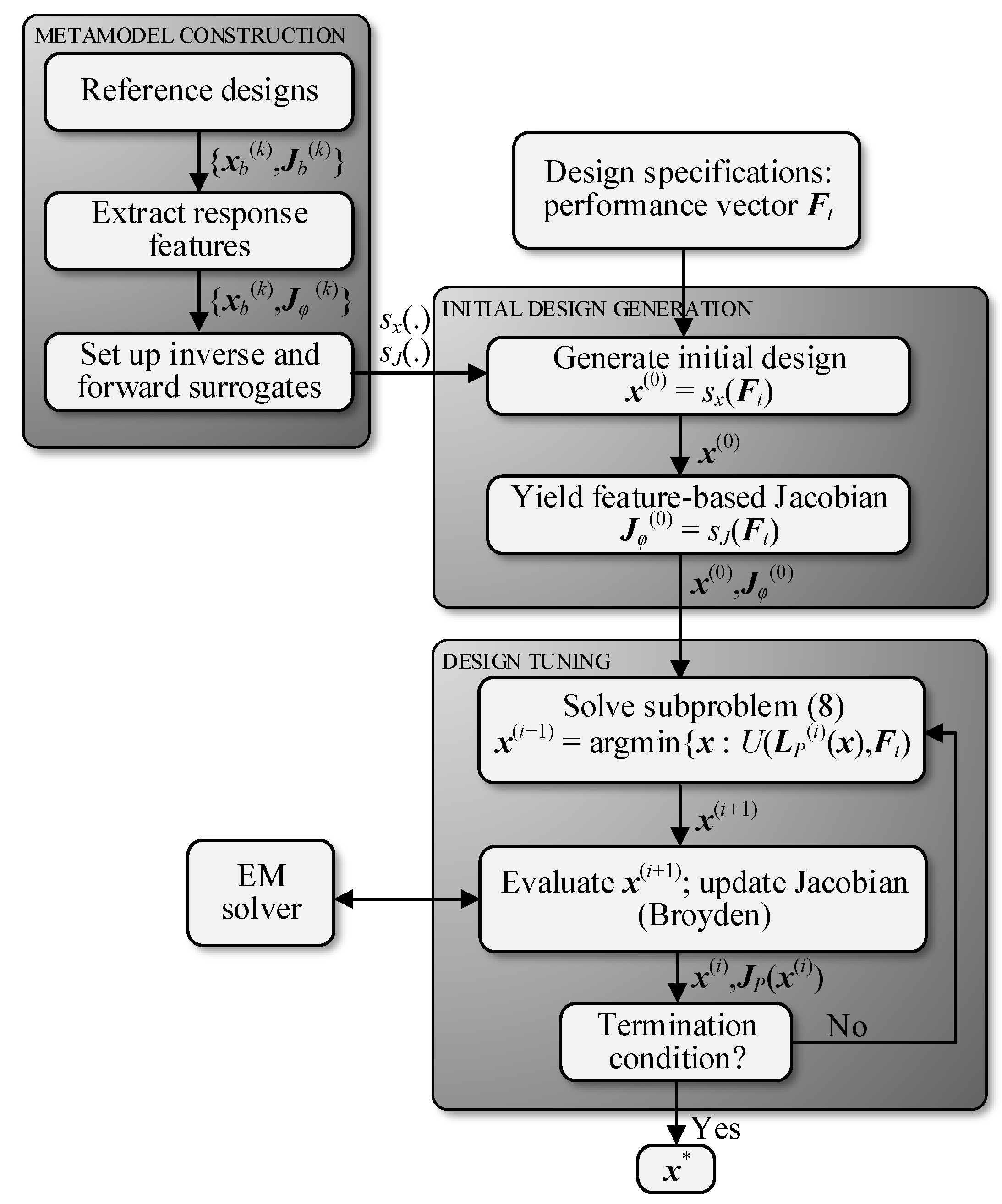
Figure 6 shows the flow diagram of the proposed optimization framework, and its three main components, i.e., construction of the inverse and forward surrogate, rendition of both the starting point as well as the initial Jacobian matrix, and the final design tuning procedure.
3. Demonstration Case Studies and Benchmarking
This section provides a demonstration of the proposed surrogate-assisted optimization framework using two structures: a branch-line [
60] and a rat-race coupler [
61], described by ten and six design variables, respectively. The results show that the proposed framework is capable of yielding designs satisfying assumed design objectives at a low computational cost.
3.1. Example 1: Branch-Line Coupler
Our first verification structure is a miniaturized branch line coupler [
60].
Figure 7 shows the circuit topology which employs a high-impedance asymmetrical T-equivalent structure replacing the conventional transmission line for size reduction and return loss bandwidth enhancement. The circuit is implemented on the substrate of fixed height
h = 0.76-mm, whereas the substrate permittivity is one of the objective space components. The vector of designable parameters is
x = [
g l1r la lb w1 w2r w3r w4r wa wb]
T. The relationships between other parameters are as follows:
L = 2
dL +
Ls,
Ls = 4
w1 + 4
g +
s +
la +
lb,
W = 2
dL +
Ws,
Ws = 4
w1 + 4
g +
s + 2
wa,
l1 =
lbl1r,
w2 =
waw2r,
w3 =
w3rwa, and
w4 =
w4rwa,
s =
g and
dL = 15 mm is fixed. All dimensions are expressed in mm except those with
r-subscript which are relative. The computational model is implemented in CST Microwave Studio.
The following design objectives are considered: (i) the coupler matching and isolation are to be below −20 dB at the frequency f0, and, at the same time, (ii) equal power split, i.e., |S21(x, f0)| = |S31(x, f0)|, is to be ensured. The conditions (i) and (ii) are to be achieved for a given substrate permittivity εr. For this case study, the ranges of the performance figures are 1.0 GHz ≤ f0 ≤ 2.0 GHz, and 2.0 ≤ εr ≤ 5.0. The assumed number of the database designs is nine, and they correspond to the following performance figures pairs {f0, εr} = {1.0, 5.0}, {1.5, 5.0}, {2.0, 5.0}, {1.0, 3.5}, {1.5, 3.5}, {2.0, 3.5}, {1.0, 2.0}, {1.5, 2.0}, and {2.0, 2.0} (frequency in GHz). These designs have been used to set up both the inverse model sx and the feature-based forward surrogate sJ.
Numerical verification of the proposed methodology for the branch-line coupler of
Figure 7 has been performed for the objective vectors
Ft provided in
Table 1, where the detailed optimization results are also given.
Table 2 gathers the optimized branch-line coupler (BLC) dimensions, whereas
Figure 8 shows the initial and optimized characteristics of the circuit. The initial designs of
Figure 8 are yielded for the target operating conditions
Ft by the inverse metamodel
sx as
x(0) =
sx(
Ft), and the optimized designs are fine-tuned according to the procedure delineated in
Section 2.4, where the feature-based Jacobian is jump-started with
Jφ(0) =
sJ(
Ft). The average computational cost of yielding the optimal design is just nine full-wave EM analyses. The quality of the optimal designs is quantified by the value max(
S11(
f0),
S41(
f0)), i.e., the maximum value of the matching and isolation characteristics at the target operating frequency
f0, as well as the obtained power split
dS = |
|S21(
f0)| − |
S31(
f0))|| at
f0. In the proposed framework, the average value of the former equals –23.6 dB, whereas the latter does not exceed 0.03 dB for all the optimized designs (see also
Table 1). For this verification case, the non-feature-based warm-start optimization procedure reported in [
53] failed to provide satisfactory results for all the target vectors of
Table 1. This is due to the fact that the accuracy of the forward sensitivity model is in this case poor. In other words, the information comprised in nine reference designs did not provide a reliable representation of the sensitivity of the circuit response, yet it was sufficient to set up the sensitivity feature-based metamodel of satisfactory predictive power.
As mentioned above, a straightforward comparison between the proposed feature-based technique and its original counterpart (not relying on response features) is not possible for the verification example of this section. An indirect comparison may be made with the methodology of [
53] applied for three- and four-section impedance matching transformers described by ten and fifteen geometry parameters, respectively. In [
53], derivative-free forward metamodel was sufficiently accurate to reliably represent the sensitivities of the device at hand and the high-quality optimal designs were obtained at the average cost of eight EM analyses (per design). The proposed approach may also be compared to the work of [
62], where the branch line coupler of
Figure 7 has been optimized directly, i.e., without jump-starting the Jacobian. In that case, the average cost of the optimization process [
62] has been considerably higher and exceeded 70 EM simulations per design. An important remark is that, in general, a local optimization procedure requires good starting point being sufficiently close to the optimal solution. In our approach, such high-quality initial designs are yielded by the inverse metamodel, thereby allowing to expedite the optimization process.
3.2. Example 2: Rat-Race Coupler
Our second demonstration example is a compact rat-race coupler (RRC) [
61] shown in
Figure 9. The circuit employs a defected microstrip structure (meander spurline) within a folded transmission line. The slow-wave effect of the meander spurline allows for reducing the size of the coupler. Further size reduction is obtained by folding the part of the structure to the inside. The RRC is described by the following independent parameters
x = [
L1 br g hfr s lfr]
T. All dimensions are expressed in mm except for the relative quantities with
r-subscript which are unitless. The following relationships hold
L2 =
L1 −
g −
w0,
a = (
lf − 17
s)/16,
b = (
hf −
s)
br,
lf =
L2 lfr,
lv =
L1 − 2
g − 2
w0, and
hf =
s + (
w0 −
s)
hfr. The fixed parameters are
dW =
dL = 10 mm, whereas the input line width
w0 is computed for a given substrate permittivity
εr so as to ensure 50 Ω input impedance. The computational model is implemented in CST Microwave Studio.
As in the previous case, the design objectives include (i) ensuring the coupler matching and isolation below −20 dB at the operating frequency
f0, and (ii) achieve equal power split. The same ranges of the design objectives are considered, i.e., 1.0 GHz ≤
f0 ≤ 2.0 GHz, and 2.0 ≤
εr ≤ 5.0. Furthermore, nine database designs have been used to set up the entire framework, and they correspond to the performance figures pairs listed in
Section 3.1.
The methodology outlined in
Section 2 has been also validated by optimizing the rat-race coupler of
Figure 9.
Table 3 gathers the selected target objective vectors
Ft, as well as the optimization results and computational cost. The geometry parameters of the optimized designs are provided in
Table 4.
Figure 10 shows the coupler
S-parameters for the initial and optimized designs. The average computational cost of design optimization for this verification case is as low as six full-wave EM analyses. The quality the optimal designs is quantified by the higher of the values of the matching and isolation characteristics at the target operating frequency
f0, the average value of which for the presented example and for all the target objective vectors is slightly below −20 dB. In this case, the average value of the power split at
f0 is around 0.1 dB. As for the previous example, the framework of [
53], in which the forward sensitivity model has been based on the entire frequency response of the coupler, failed to yield satisfactory results. Therefore, only an indirect comparison may be made with the results of optimizing the same structure with the use of the classical approach [
62]. In [
62], the computational cost of yielding optimal RRC geometries exceeded 50 EM analyses.
In order to put the methodology considered in this work in the context of state-of-the-art techniques reported in the literature,
Table 5 provides a qualitative comparison with selected global search methods involving both direct optimization of EM simulation models of high-frequency structures using particle-swarm optimization algorithm (PSO) [
24,
25,
26,
27], arguably one of the most popular nature-inspired techniques, and surrogate-assisted approaches [
40,
41]. On the one hand, it can be observed that our approach is significantly more efficient in computational terms, as well as allows for handling higher-dimensional problems. On the other hand, these advantages result from utilization of the reference designs, which indicates the importance of exploiting the problem-specific knowledge whenever possible.
4. Conclusions
The paper proposed a framework for expedited re-design of compact microwave components. Our procedure exploits a database comprising a limited number of pre-optimized designs, along with the inverse and forward feature-based metamodels. The primary contribution of the proposed methodology consists in the incorporation of the response feature technology into the warm-start algorithm. For the presented verification cases, a branch-line and a rat-race coupler, constructing the forward sensitivity metamodel at the level of the response features rather than the entire frequency characteristics allowed for modeling the circuit sensitivities in a reliable manner. As a matter of fact, carrying out the optimization process with the use of the non-feature-based forward surrogates turned out to be impossible due to the limited accuracy of the latter. This indicates that for the considered class of miniaturized microwave structures, modeling sensitivities at the level of the response features is instrumental in achieving satisfactory results. Another advantage of the proposed approach is a small computational cost of yielding high-quality designs satisfying the assumed design specifications, which has been less than a dozen of full-wave simulations for all the presented verification cases.
As for the limitations of the proposed framework, it can be considered a suitable tool for cost-efficient and reliable solving of optimization tasks whenever a set of already existing designs is readily available for a structure at hand that would serve for setting up the inverse and forward surrogates employed by our technique. Another area of employing the presented methodology are the situations when the initial expenditures of database designs acquisition are justifiable by repetitive future reuse of the framework. Nevertheless, the overall cost of both surrogate construction and rendering the optimal designs is significantly lower than the cost offered by either the methods employing conventional surrogates or the optimization techniques using population-based optimizers.
Moreover, the scope of applicability of our method is limited to structures whose responses feature well distinguished characteristic points. Nevertheless, the characteristics of many real-world microwave components are essentially structured (e.g., couplers or multi-band transformers). Therefore, the employment of the feature-based techniques for such structures is not impeded by the aforementioned factors. Furthermore, the presented methodology may also be applied to antenna structures, in particular, narrow-band or multi-band antennas, to allocate their resonances at the required target frequencies.
Improving the efficiency of our approach is possible by automating the process of rendering the reference designs and lowering its cost. Another way of improving the versatility of the technique is to develop a generalized definition of features points that would be less dependent on a particular structure of the component response. This would allow for to preserving the consistency of the feature set across the parameter space and permit applying the proposed approach to a wider class of high-frequency structures.


