Abstract
A digital control scheme for GaN transistor-based totem pole power factor correction (PFC) is proposed in this paper. At the zero crossing, the totem pole PFC has a discontinuous conduction mode (DCM) current section because of its driving method and circuit structure. In the DCM current section, when a typical synchronous switching technique is applied, the inductor current is reduced to less than zero, thereby reducing efficiency. Moreover, because of the nature of the circuit, power may be transferred in reverse. To prevent this, a new synchronous switch technique using the cycle by cycle (CBC) trip function of the digital signal processor (DSP) is proposed. This proposed technique turns off the synchronization switch according to the set DCM level. Consequently, even at a low DCM level, the inductor current is clamped to zero, enabling stable synchronous switching.
1. Introduction
Environmental and energy problems have recently become more severe; accordingly, the efficient use of limited resources has become necessary. Considerable efforts have also been devoted to the field of power electronics, which is closely related to the efficient use of energy. Research on alternating current (AC)–direct current (DC) power conversion systems has actively been conducted. These devices are essential not only for improving the power factor (PF) and quality but also for reducing harmonics [1]. These, PFCs are essentially used in energy storage applications. Typical applications PFC boost converters include inefficient bridge diodes. Accordingly, the interest in bridgeless PFCs capable of reducing conduction losses and enhancing the efficiency of energy use has increased.
The totem-pole PFC, a representative bridgeless PFC topology, has the advantage of reducing both conduction loss and common-mode electromagnetic interference (EMI) [2,3,4,5,6]. The conventional totem-pole PFC uses the Si MOSFET as the main switching element. Hence, when operating in the continuous conduction mode, a severe reverse recovery problem encountered by the body diode occurs, consequently reducing efficiency and reliability [7]. Gallium nitride (GaN) transistors, which are representative next-generation power semiconductor devices, are among the features of wide-band gap semiconductors with excellent reverse recovery characteristics and low switching loss; they also have the capacity to operate at high temperatures [8,9,10,11]. Excellent reverse recovery characteristics can resolve the problems of existing Si-based totem-pole PFCs as well as optimize performance and efficiency [12,13].
The advancements in semiconductor technology and the wide use of this technology in the field of power electronics have improved the performance of digital controllers. Digital controllers are more complex than analog controllers and have the advantage of enabling various pulse width modulation (PWM) controllers. In addition, it is possible to develop a flexible system using a communication function [14,15]. Based on these advantages, various studies using digital controllers for GaN-based totem-pole PFC control are conducted [15,16,17,18]. In particular, the totem-pole PFC topology, which can be employed for bidirectional applications, requires a digital controller.
The totem-pole PFC is divided into low-frequency and high-frequency switching legs with line and switching frequencies, respectively. Such a circuit configuration creates various problems near the zero crossing of the AC voltage. The problem intensifies as the difference between low and high frequencies increases owing to the application of GaN transistors [7]. Typical problems include reverse operation due to current spikes and discontinuous conduction mode (DCM) of current. The solution to the current spike problems has been reported in many previous papers [19,20,21,22]. To improve the efficiency of the PFC and reduce the heat generation in GaN transistors, synchronous PWM operation technology is generally applied. However, synchronous PWM operation triggers the switch even if the inductor current drops to zero around the zero crossing. In this switch operation, the current path is maintained by discharging the output capacitor at the input source. This switching sequence has a negative effect on the circuit. It also causes current spike problems, making the control loop unstable and affecting total harmonic distortion (THD) [8,23]. To preclude this, a common approach is to operate in synchronous PWM mode when the inductor current increases above the DCM level. In particular, the DCM current level must be higher for stable driving of GaN transistors with low gate source voltage (VGS) characteristics. However, this reduces the efficiency. Therefore, there is a need for a synchronous PWM control technique to improve efficiency even at a low DCM current.
Accordingly, in this paper, a digital driving method for a GaN transistor-based totem-pole PFC is proposed. In the study, first, the basic operating characteristics of the totem-pole PFC are analyzed, and a digital control technique using a digital signal processor (DSP) is formulated. In particular, the method provides an optimal PWM control solution to prevent the reverse operation due to the DCM current at the zero crossing. Finally, the proposed digital control technique is verified by applying a digital controller to a 1 kW totem-pole PFC.
2. Totem-Pole Bridgeless PFC
2.1. Operation of Totem-Pole PFC
The totem-pole PFC circuit is shown in Figure 1. All four H-bridge switches are configured as active switches. The high-frequency leg is composed of GaN transistors and the low-frequency leg is composed of Si-MOSFET.
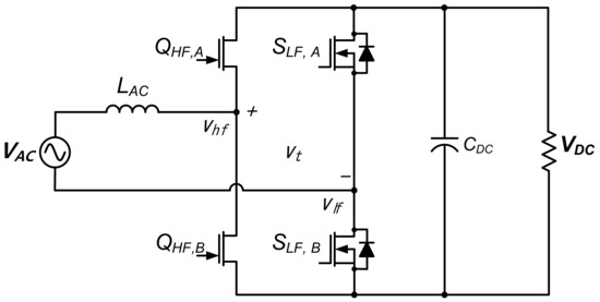
Figure 1.
Circuit of totem-pole bridgeless power factor correction (PFC).
As indicated Equation (1), when a full-bridge voltage (Vt) is supplied, the AC current is in phase with the voltage. The required duty cycle in relation to Vt is given by Equation (2).
In the totem-pole PFC configuration, the low-frequency legs rectify the line frequency. The duty cycle pattern for each leg of the full bridge should be equal to those given by Equations (3) and (4) [7].
where dhf and dlf are the duty cycles of the high-frequency and low-frequency legs, respectively. Specifically, in the positive half cycle of the AC voltage, QHF,B and QHF,A function as the main and synchronous switches, respectively; in the negative half cycle of the AC voltage, they operate in reverse. Figure 2a shows the power flow according to the switching operation during the positive half cycle of the AC voltage, and Figure 2b shows that in the negative half cycle.
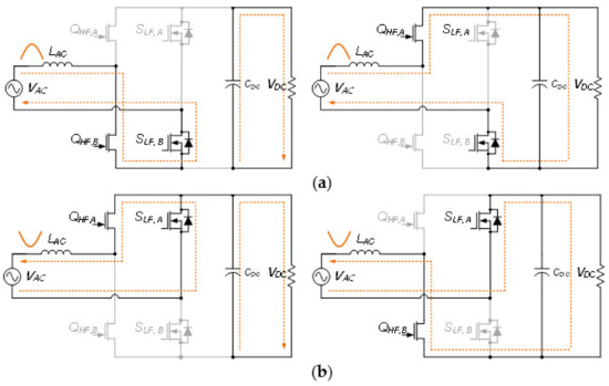
Figure 2.
Stages of operation for totem-pole PFC. (a) positive half and (b) negative half.
2.2. Synchronous PWM Techniqu in DCM Current Section
The key switching waveform for the AC voltage cycle is shown in Figure 3a. The SLF,A/B of the low-frequency leg is synchronized with the frequency of the AC voltage and operates on-off according to the phase. The QHF,A/B of the high-frequency leg operate at the switching frequency. It operates as a main switch and a synchronous switch according to the phase.
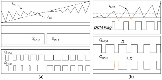
Figure 3.
Key waveforms of the totem-pole PFC. (a) waveforms of basic operation and (b) detail waveforms of synchronous pulse width modulation (PWM) at positive half.
Figure 3b shows the waveform of a typical synchronous PWM method. When the DCM level is high, the synchronous mode is activated. Usually, the control loop of a digital controller operates in the middle region of the main switch, for measuring the continuous conduction mode current of the inductor. Therefore, even if the PWM DCM flag is changed to Low as shown in Figure 3b, the preset controller is maintained, and the synchronization switch is turned on to 1-D. In the switching-on process, the inductor current drops below zero by discharging the output capacitor at the input source. If it decreases below zero, the input current increases and the total conduction losses increase. It also affects THD by making the current spike problem and the control loop unstable. To solve the above problem, synchronous PWM is usually operation at a higher DCM level, but during this period, conduction losses increase and efficiency decreases.
To set the DCM level, the Schmitt trigger circuit is applied, as shown in Figure 4a. The Schmitt trigger provides hysteresis for the inductor current to reduce the glitches in the DCM flag caused by the current ripple. The high and low levels of DCM current can be obtained using Equations (5) and (6), respectively.
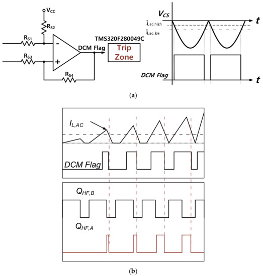
Figure 4.
Proposed CBC trip-type synchronous PWM operation method. (a) Schmitt trigger circuit for DCM flag and (b) proposed synchronous PWM method.
The proposed method receives the DCM flag for the digital controller TZ. When the DCM flag is high, it operates as a general synchronous PWM; however, when the DCM flag is active low, the TZ’s CBC trip interrupt is enabled. The synchronous PWM is forcibly turned off by a high-priority TZ interrupt. The key waveforms are shown in Figure 4b. The inductor current is not reduced to less than zero because turning off the synchronous switch causes the current to pass through the body diode. This control technology can improve efficiency by stably operating the synchronous rectifiers even for only a brief period before the DCM level is reached.
3. Digital Control Technique for Totem-Pole PFC
3.1. Digital Controller for Totem-Pole PFC
The digital controller was configured using the TMS320F280049C DSP (Texas Instruments), which can implement a relatively high 100 MHz system clock and a high degree of freedom trip zone (TZ). In particular, it was employed because it included various functions for the PWM. The block diagram of the digital controller with the DCM monitor circuit is shown in Figure 5. The AC current is fed back by placing a shunt resistor on the low-frequency leg, as shown on the circuit in Figure 4. The voltage (VCS) across the shunt resistor is also used in the DCM monitor circuit. The DCM monitor circuit output is connected to the CBC TZ and applied to the high frequency switching modulation. The voltage controller performs proportional–integral (PI) regulation in a typical double-loop structure.
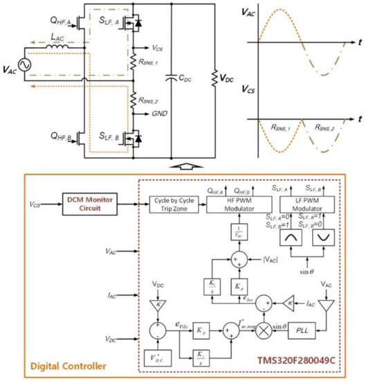
Figure 5.
Control block diagram of totem-pole PFC using digital signal processor (DSP).
3.2. DSP-Based Digital PWM Implementation for Totem-Pole PFC
In this study, the PWM counter (PC) is set as an up–down counter. The PC increases or decreases with the cycle of the switching frequency. If PC = 0, then the analog-to-digital converter (ADC) starts, and the set value is applied to the register. Set the action qualifier to read the current starting from PC = 0, i.e., the middle point of the main switch according to the AC voltage polarity change, as shown in Figure 6. The PWM is differently outputted even if the same duty is applied according to the AC voltage polarity change. Regardless of the AC voltage polarity, the comparator value (CMP) is computed as given by Equation (7). Where, maximum PWM counter (PCMAX) value depends on the switching frequency and the DSP system clock.
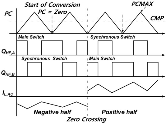
Figure 6.
Action qualifier setting by polarity change for constant start of conversion (SOC).
The digital phase look loop (PLL) is used to estimate the phase angle (θ) of the AC voltage. The estimated θ is used in the digital controller’s sine function and is synchronized with the AC voltage phase. The low frequency legs turned on and off according to the SINE(θ). As a result, the low frequency legs are operation at the line frequency.
Table 1 also lists the PWM action qualifier setting according to the PC event where the synchronous switch operation by the CBC trip is omitted.

Table 1.
Action qualifier setting for PC event for totem-pole PFC.
3.3. Control Strategy for Totem-Pole PFC
As shown in Figure 7a, the digital control algorithm of totem-pole PFC is implemented by dividing it into six modes based on AC voltage period. As described, the setting of the action qualifier changes according to the AC voltage polarity; hence, it is complementarily controlled in three modes. The state machine for each mode of operation is shown in Figure 7b.
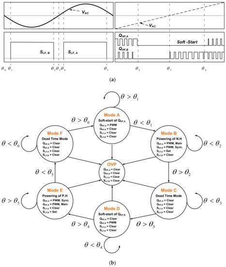
Figure 7.
Control mode by the alternating current (AC) voltage period. (a) gate waveforms by AC voltage period and (b) state machine of totem-pole PFC by mode.
The detailed mode description is as follows.
- A Mode (θ0 > θ > θ1): This is a soft start section of QHF,A of the high-frequency leg, and the duty of QHF,A is gradually increased and outputted. When θ ≤ θ1, the mode ends after the PI controller variable initialization and QHF,B switch activation.
- B Mode (θ1 > θ < θ2): This is a mode in which the PI controller operates and performs negative powering. In this mode, the synchronous PWM control technique using the CBC trip function is applied. When θ ≥ θ2, the mode is terminated by disabling all PWM outputs.
- C Mode (θ2 < θ < θ3): This mode is a dead period during which all switches are turned off to prevent current spikes caused by the zero crossing. The variables to be applied to the next mode, i.e., the soft start mode, are initialized. When θ ≥ θ3, the mode is terminated after activating the PWM of QHF,B.
- D Mode (θ3 < θ < θ4): This is the soft start section of QHF,B of the high-frequency leg. In this mode, the duty of QHF,B is gradually increased and outputted. When θ ≥ θ4, the mode ends after the initialization of the PI controller variable and activation of the QHF,A switch.
- E Mode (θ4 < θ > θ5): Similar to the B mode, only the main switch is changed. When θ ≤ θ5, this mode ends after disabling all PWM outputs.
- F Mode (θ5 < θ < θ0): Similar to the C mode, when θ ≤ θ0, the mode is terminated after activating the PWM of QHF,A.
- Over Voltage Protection (OVP): If VDC > 430VDC, Turn-off all switches for system protection.
4. Experimental Verification
The experimental results are presented in this section. A digital controller using TMS320F280049C was designed and developed to implement the proposed digital control technology. The 1 kW totem-pole PFC prototype is designed to validate the digital control technology. A totem-pole PFC prototype with a digital controller is shown in Figure 8a. The GaN transistor of GaN Systems (GS66508B) and Si MOSFET of Infineon (IPT65R033) are used as high and low-frequency drive legs, respectively. The detailed specifications are summarized in Table 2.
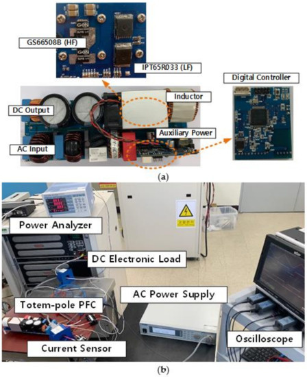
Figure 8.
Experiment environment of digital control-based totem Pole PFC. (a) prototype of totem-pole PFC using GaN transistor and (b) experimental configuration of test bench.
Table 2.
Specifications and circuit parameters of the totem-pole PFC.
As shown in Figure 8, the experimental set is configured for the load test of the totem-pole PFC. AC power supply of Extech was used to supply the AC power of the prototype. The DC electronic load of Sorensen was utilized in the variable load experiment; the load variation was 20–100%. The WT330 power analyzer is used to measure input/output efficiency, THD for input current, and PF. The switching characteristics of the oscilloscope were used for the gate waveform and input/output waveform analysis.
Figure 9a shows the gate waveform and inductor current waveform of the conventional synchronous PWM method. In the existing method, even if the DCM flag is changed to low, the synchronous switch is essentially turned on by 1-D. The current is reduced to less than zero because this switch is turned on.
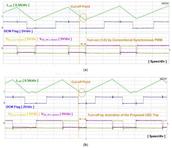
Figure 9.
Key waveforms by synchronous PWM operation method. (a) conventional synchronous PWM method and (b) proposed synchronous PWM method.
Figure 9b shows the gate waveform of the proposed CBC trip-type synchronous PWM method. When the DCM flag is low active, the synchronous switch is turned off by the CBC trip. When the synchronous switch is turned off, the current flows through the body diode. Note that the inductor current is clamped to zero.
Figure 10 shows the operating waveforms at a 10% load condition at 220 VAC input. Under both experimental conditions, the DCM level is the same. Figure 10a shows a waveform with conventional synchronous PWM technology, and Figure 10b shows a test waveform with the proposed synchronous PWM technique. Under light load conditions where the DCM period is frequent, the inductor current drops to less than zero, and the current control is unstable. By contrast, in the proposed technique, the current is clamped to zero and stably operates in the DCM section. As a result, the efficiency and THD improved by 0.4% and 4.42%, respectively, as summarized in Table 3. In the conventional synchronous PWM technology, the DCM level should be increased to improve the control reliability of the DCM section, causing the efficiency to further decrease.
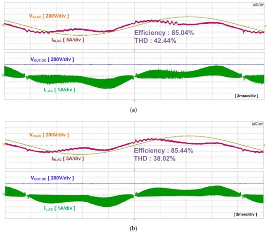
Figure 10.
Operation waveform at light load (10%). (a) conventional synchronous PWM method and (b) the proposed synchronous PWM method.
Table 3.
Comparison of experimental results between the conventional and the proposed methods.
Figure 11 shows the operating waveforms for the input and output under rated conditions. The CBC trip-type synchronous PWM driving technology can stably operate switching at the zero crossing. Figure 12 shows the efficiency characteristics according to the load. Under the 1 kW rated conditions, the following are achieved: 98.63% efficiency, 0.99 PF, and 4.7% THD. Based on the experimental results, the proposed technique, which employs a wide DCM section, exhibits safe performance and high efficiency under light load conditions.
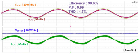
Figure 11.
Steady-state waveforms at 1 kW output power.
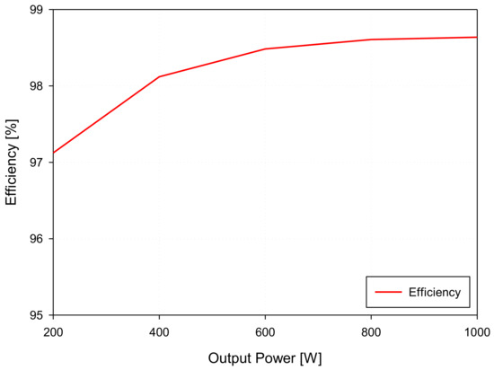
Figure 12.
Efficiency characteristics by output power.
5. Conclusions
In this paper, a digital control scheme for a GaN transistor-based totem-pole PFC is proposed. In a typical totem-pole PFC, the high-frequency legs are operated in a synchronous PWM method to achieve high efficiency. The totem-pole PFC has a DCM current section at the zero crossing because of its driving method and circuit structure. In this section, a typical synchronous PWM triggers the switch even if the inductor current drops to zero around the zero crossing. In this switch operation, the current path is maintained by discharging the output capacitor at the input source. This switching sequence has a negative effect on the circuit. It also causes current spike problems, making the control loop unstable and affecting THD. To avoid this problem, synchronous switching techniques are usually applied after the inductor current is at the DCM level. However, due to the high level of DCM, system efficiency is reduced. Therefore, the CBC trip-type synchronous PWM technique is proposed to turn off the synchronous switch according to the DCM level. This control technique turn-off the synchronous switch off according to the DCM level, clamping the inductor current to zero, resulting in a stable synchronous PWM is implemented even at lower DCM levels. To verify the proposed control technology, a 1 kW GaN-based totem-pole PFC and DSP-based digital controller are designed and developed. The experimental results showed that the DCM section improved the efficiency and THD. under a light load. Compared with the conventional control technique, the efficiency and THD improved by approximately 0.5% and 4.42%, respectively. In the above results, increasing the DCM level to improve THD, on the contrary, will increase the efficiency difference. Finally, the achieved efficiency, P.F, and THD are 98.63%, 0.99, and 4.7%, respectively, at the 1 kW rated load. Hence, the proposed technology can improve the efficiency and THD of the totem-pole PFC under light load conditions and increase the stability in the zero crossing.
Author Contributions
Conceptualization, B.K.; methodology, validation, analysis, and analyzed the data, B.K., and J.K.; writing—original draft, B.K.; Writing—review and editing, supervision, and project administration, J.K. All authors have read and agreed to the published version of the manuscript.
Funding
This study has been conducted with the support of the Ministry of Trade, Industry and Energy as “Future Growth Engine Business project (20003558)”.
Institutional Review Board Statement
Not applicable.
Informed Consent Statement
Not applicable.
Data Availability Statement
The data presented in this study are available in article.
Conflicts of Interest
The authors declare no conflict of interest.
References
- Liao, Y.H. A Step Up/Down Power Factor Correction Converter with Modified Dual Loop Control. Energies 2020, 13, 199. [Google Scholar] [CrossRef]
- Huber, L.; Yungtaek, J.; Jovanovic, M.M. Performance Evaluation Bridgeless PFC Boost Rectifiers. IEEE Trans. Power Electron. 2008, 23, 1381–1390. [Google Scholar] [CrossRef]
- Jang, Y.; Jovanovic, M.M. A bridgeless PFC boost rectifier with optimized magnetic utilization. IEEE Trans. Power Electron. 2009, 24, 85–93. [Google Scholar] [CrossRef]
- Choi, W.Y.; Kwon, J.M.; Kim, E.H.; Lee, J.J.; Kwon, B.H. Bridgeless boost rectifier with low conduction losses and reduced diode reverse-recovery problems. IEEE Trans. Ind. Electron. 2007, 54, 769–780. [Google Scholar] [CrossRef]
- Pengju, K.; Shuo, W.; Lee, F.C. Common mode EMI noise suppression for bridgeless PFC converters. IEEE Trans. Power Electron. 2008, 23, 291–297. [Google Scholar]
- Su, B.; Lu, Z. An interleaved Totem-Pole Boost Bridgeless Rectifier with Reduced Reverse-Recovery Problems for Power Factor Correction. IEEE Trans. Power Electron. 2010, 25, 1406–1415. [Google Scholar]
- Xue, L.; Shen, Z.; Boroyevich, D.; Mattavelli, P. GaN-based high frequency totem-pole bridgeless PFC design with digital implementation. In Proceedings of the 2015 IEEE Applied Power Electronics Conference and Exposition (APEC), Charlotte, NC, USA, 15–19 March 2015; pp. 759–766. [Google Scholar]
- Zhou, L.; Wu, Y.; Honea, J.; Wang, Z. High-efficiency true bridgeless totem-pole PFC based on GaN HEMT design challenges and cost-effective solution. In Proceedings of the International Exhibition and Conference for Power Electronics, Intelligent Motion, Renewable Energy and Energy Management, PCIM Europe 2015, Nuremberg, Germany, 19–20 May 2015; pp. 1–8. [Google Scholar]
- Persson, E. How 600 V GaN transistors improve power supply efficiency and density. Power Electron. Eur. 2015, 2, 21–24. [Google Scholar]
- Keshmiri, N.; Wang, D.; Agrawal, B.; Hou, R.; Emadi, A. Current status and future trends of GaN HEMTs in electrified transportation. IEEE Access 2020, 8, 70553–70571. [Google Scholar] [CrossRef]
- Li, X.; Ma, H.; Yi, J.; Lu, S.; Xu, J. A Comparative Study of GaN HEMT and Si MOSFET-Based Active Clamp Forward Converters. Energies 2020, 13, 16. [Google Scholar]
- Ma, C.T.; Gu, Z.H. Review of GaN HEMT Application in Power Converter over 500W. Electronics 2019, 8, 1401. [Google Scholar] [CrossRef]
- Liu, Z. Design of GaN-Based MHz Totem-pole PFC Rectifier. IEEE J. Emerg. Sel. Top. Power Electron. 2016, 4, 799–807. [Google Scholar] [CrossRef]
- Fei, C.; Feng, W.; Lee, F.C.; Li, Q. State-trajectory control of LLC converter implemented by microcontroller. In Proceedings of the 2014 IEEE Applied Power Electronics Conference and Exposition—APEC 2014, Fort Worth, TX, USA, 16–20 March 2014; pp. 1045–1052. [Google Scholar]
- Fei, C.; Lee, F.C.; Li, Q. Digital implementation of adaptive synchronous rectifier (SR) driving scheme for LLC resonant converters. In Proceedings of the 2016 IEEE Applied Power Electronics Conference and Exposition (APEC), Long Beach, CA, USA, 20–24 March 2016; pp. 322–328. [Google Scholar]
- Liu, Z.; Huang, Z.; Lee, F.C.; Li, Q. Digital-based interleaving control for GaN-based MHz CRM totem-pole PFC. IEEE J. Emerg. Sel. Top. Power Electron. 2016, 4, 1847–1852. [Google Scholar]
- Fischer, G.S.; Rech, C.; Novaes, Y.R. Extensions of Leading-Edge Modulated One-Cycle Control for Totem-Pole Bridgeless Rectifiers. IEEE Trans. Power Electron. 2019, 35, 5447–5460. [Google Scholar] [CrossRef]
- Lamo, P.; Lopez, F.; Pigazo, A.; Azcondo, F.J. Stability and Performance Assessment of Single-Phase T/4 PLLs With Secondary Control Path in Current Sensorless Bridgeless PFCs. IEEE J. Emerg. Sel. Top. Power Electron. 2018, 6, 674–685. [Google Scholar] [CrossRef]
- Paschedag, D.; Ferdowsi, M. Elimination of zero-crossing distortion in a power factor correction circuit. In Proceedings of the Energy Conversion Congress and Exposition (ECCE), Raleigh, NC, USA, 15–20 September 2012; pp. 4049–4052. [Google Scholar]
- Sun, J. On the zero-crossing distortion in single-phase PFC converters. IEEE Trans. Power Electron. 2004, 19, 685–692. [Google Scholar] [CrossRef]
- Siddique, R.A.; Khandekar, R.; Ksiazek, P.; Wang, J. Investigation of Zero-Crossing Common-Mode Noise and Current Spike in GAN Based Totem-Pole PFC. In Proceedings of the 2018 IEEE Canadian Conference on Electrical & Computer Engineering, Quebec City, QC, Canada, 13–16 May 2018. [Google Scholar]
- Zhang, B.; Imaoka, J.; Shoyama, M.; Tomioka, S.; Takegami, E. Study on zero-crossing conducted noise issue of totem-pole bridgeless PFC converter. In Proceedings of the 2017 IEEE 3rd International Future Energy Electronics Conference and ECCE Asia, Kaohsiung, Taiwan, 3–7 June 2017; pp. 2233–2237. [Google Scholar]
- Mai, L.S.; Rospirski, A.; Mussa, S.A.; Lazzarin, T.B. Totem-Pole Bridgelss PFC Converter in DCM with Synchronous Rectification. In Proceedings of the 2019 IEEE 15th Brazilian Power Electronics Conference and 5th IEEE Southern Power Electronics Conference, Santos, Brazil, 1–4 December 2019. [Google Scholar]


Publisher’s Note: MDPI stays neutral with regard to jurisdictional claims in published maps and institutional affiliations. |
© 2020 by the authors. Licensee MDPI, Basel, Switzerland. This article is an open access article distributed under the terms and conditions of the Creative Commons Attribution (CC BY) license (http://creativecommons.org/licenses/by/4.0/).