1. Introduction
Many countries around the world are strengthening their carbon emission regulations under the Paris Agreement, which was drawn up by leaders from all over the world to address global climate change. In response to this trend, new research approaches are being developed throughout the industry to improve the power conversion efficiency of systems or to use renewable energy technology to replace fossil fuels. In the transportation sector, which accounts for more than 20% of global carbon emissions, research results suggest that railroad transportation, the most efficient means of transportation in terms of greenhouse gas emissions, needs to be expanded to reduce carbon emissions [
1]. In addition, in the railroad industry, strong carbon regulatory policies have been announced in Europe and North America, requiring changes in existing railroad systems [
2].
To cope with such carbon emission regulations, railroad vehicle propulsion systems are being researched to improve them in three cases as a way to increase the propulsion efficiency of vehicles and reduce carbon emissions.
Case 1: Installing an energy storage system (ESS) in the railroad substation that supplies power to the catenary—stationed ESS method [
3].
Case 2: Installing an ESS in the railroad vehicle propulsion system to save and utilize regenerative energy—on-board ESS method [
4].
Case 3: Equipping the power system to supply/store energy inside the railroad vehicle to minimize transmission loss—catenary free method [
5].
Case 1 has the advantage that it can be applied without retrofitting existing railroad vehicles because it is installed outside the vehicle. In addition, there is a limit to the need for additional facility installation and management space according to the station. Case 2 has the advantage of minimizing the loss of regenerative energy, but there is a limit to the improvement of the propulsion system of railroad vehicles because it requires additional installation of an ESS. Case 3 is an approach to maximizing the use of regenerative energy and minimizing the transmission loss of propulsion power by not using the power grid for driving the vehicle. There are two methods for implementing Case 3. The first method is to install and utilize a large-capacity ESS to store the propulsion energy of railroad cars, and the second method is to adopt an eco-friendly power system such as hydrogen fuel-cells with high-energy storage density characteristics along with the large capacity ESS. The second method is attracting the most attention as the method that can have the greatest impact on increasing energy efficiency and reducing carbon emissions, but there is a limit to its immediate commercialization because it requires research steps to design and verify the new propulsion system. All three approaches mentioned above are intended to reduce carbon emissions in railroad systems, and each method has advantages and disadvantages, so different approaches can be chosen depending on the environmental conditions. However, all of the above-described methods require a large-capacity ESS; therefore, research on the design of an ESS suitable for a railroad vehicle propulsion system is required. In this paper, we will study how to design an energy storage system for railroad vehicles using lithium batteries, which have been widely applied in recent years. In particular, the ESS design method will be studied based on the specifications of a railroad vehicle using a hydrogen fuel-cell that requires frequent charging and discharging operations in the ESS in the railroad vehicle driving profile.
2. Characteristics of ESS for Fuel-Cell Hybrid Railroad Vehicle
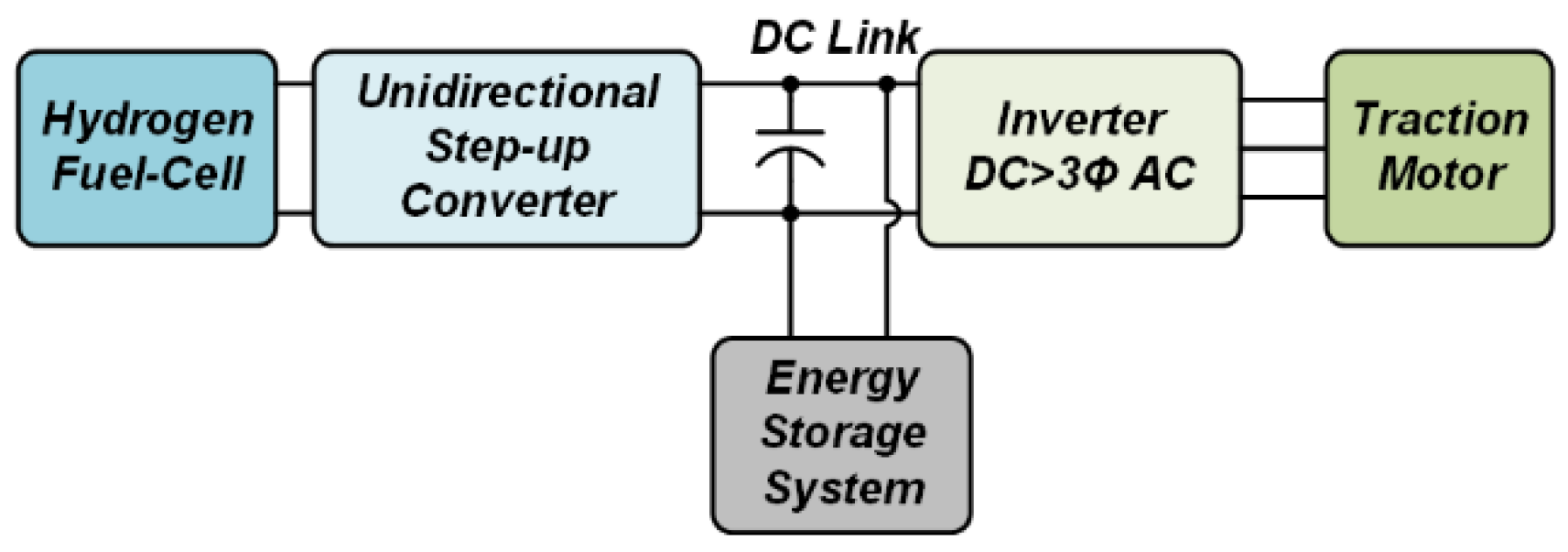
The structure of the propulsion system of the hydrogen fuel-cell hybrid railroad vehicle is shown in
Figure 1. A hydrogen fuel-cell has a unidirectional energy source characteristic and has a relatively low voltage level and high energy density compared to other energy storage devices. Accordingly, the power generated from the hydrogen fuel-cell is supplied to the traction motor through the boost converter. The ESS, which is directly connected to the DC-link of the propulsion inverter, provides the stored energy to the traction motor when powering (or accelerating) and stores the regenerated energy from the motor when braking. The propulsion inverter performs the role of traction motor control through the driving of the switches.
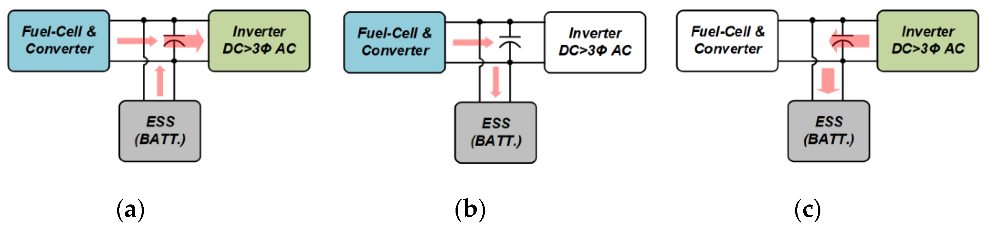
Figure 2 shows the power transmission method according to the railroad vehicle operation pattern. In powering mode, which supplies energy to the traction motor, the hydrogen fuel-cell and the ESS supply the propulsion energy. In coasting mode, where the railroad car is driven by inertial force, the power supply to the traction motor is cut off and the energy generated by the hydrogen fuel-cell is used to charge the ESS. In braking mode, regenerative energy is generated by the traction motor, which is used to charge the ESS directly connected to the inverter. As described above, the ESS constantly repeats charging and discharging operations during the driving of the railroad vehicle.
The design specifications shown in
Table 1 were selected with reference to Alstom’s hydrogen fuel-cell rail vehicle specifications currently under test in Germany [
6,
7] and the propulsion system design specifications for a heavy-rail propulsion system [
8].
Unlike fuel-cell stacks providing unidirectional power, with battery packs, both discharging and charging occur in the driving pattern of railroad vehicles. Therefore, when designing a battery pack, it is necessary to design it to be capable of supplying enough propulsion energy and receiving enough regenerative energy. Moreover, the battery pack should be connected directly to the inverter with a 1500 V level to improve the efficiency of the propulsion system. Therefore, to design the battery packs for fuel-cell hybrid railroad vehicles, it is necessary to apply parts and safety standards that were not adopted in the conventional ESSs, which have average voltage levels below 1000 V.
3. Design Considerations for High-Voltage Battery Packs
3.1. Battery System Configuration
A large capacity battery pack basically consists of a “cell-module-rack-pack”. The modules are configured through the series of parallel connections between cells, and these modules are connected in series to form a battery rack. The voltage of the battery pack is determined according to the number of modules connected in series. The battery pack connects the battery racks in parallel and adjusts the number of battery racks connected in parallel to the total battery pack capacity required by the system.
Figure 3 shows the general configuration of a battery rack and a battery pack. The battery pack consists of a plurality of battery racks with contactors and fuses, a pack battery management system (BMS) for the integrated control of the battery pack and a communication system between the railroad vehicle and the battery pack. In addition, a cooling/heating system and a power interface (power junction box with fuse) for managing and integrating a plurality of battery racks are additionally configured. The battery rack consists of a battery module, a slave BMS (SBMS) for battery module management, a master BMS for integrated management of the battery rack, a sensor for insulation/voltage/current monitoring, fuses and contactors for safety management of battery racks and emergency control for emergency management. In such a battery pack, the overall safety management and monitoring of the system is performed by the BMS. The most basic battery cell management functions—voltage/current/temperature measurement, cell-balancing and voltage/current protection—are performed in the SBMS configured in the battery module.
3.2. High-Voltage Battery System Design
3.2.1. Review of High-Voltage System Standards
Battery packs have different design criteria depending on the design specifications. Designing 1500 V high-voltage battery packs, such as battery packs for fuel-cell hybrid railroad vehicles, requires the application of national and international standards that are different from the conventional ESS. The international technical standard IEC 60479-1 (effects of current on human beings and livestock) [
9] proposes system design criteria according to the voltage level, considering the effects of high voltage on the human body. The IEC 60479-1 standard calls for variation of the hardware ground configuration of the system by dividing the class according to the voltage type (AC or DC) and the voltage level. The battery packs used for railroad propulsion systems belong to class B when the maximum voltage is less than 1500 V and double insulation is required. Above 1500 V, a system design with both double insulation and protective ground is required, as shown in
Table 2. In addition, it should be designed and properly installed according to the railroad vehicle electrical equipment safety standards IEC 61991 (railroad applications—rolling stock—protective provisions against electrical hazards), railroad vehicle electrical equipment requirements IEC 60077 (railroad applications—electric equipment for rolling stock) and IEC 62128 (railroad applications—fixed installations) [
10].
Table 3 shows a breakdown of some of the voltage standards to be considered when designing a battery pack.
3.2.2. The Fuse and Contactor Selection Criteria According to Voltage
As the voltage of the battery pack is increased, it is essential to select components in consideration of the increased voltage rating when selecting the components constituting the rack unit or pack unit system. These components are fuse and contactor parts.
Figure 4 shows the volume of commercial fuse and contactor according to voltage ratings and current ratings. As shown in
Figure 4, both fuses and contactors have a feature that increases volume by more than two times with respect to a 2000 V voltage level that lowers the power density of the system. Therefore, it is necessary to consider these effects when designing the voltage levels of battery packs.
4. Cell-Balancing Methods for Battery Packs for Railroad Vehicles
4.1. Operation Pattern of the Battery Pack
Electric-powered railroad vehicles run in urban areas, normally with a repeating pattern of “powering-coasting-braking-stop (at the station)” and they are operated continuously for more than 10 h per day [
11]. A long-repeated operation pattern is a disadvantage in terms of batteries compared to those used in other industries, such as electric vehicles or industrial ESS. In particular, in the case of the battery packs used for railroad vehicles powered by hydrogen fuel-cells, the charging and discharging operation of the battery packs is constantly represented. The battery packs are discharged during the powering operation of railroad vehicles, and the discharged energy is recharged during coasting, braking and stop operation. The operation characteristic of having no rest time of the battery packs adversely affects the lifetime of the batteries [
12]. Under these conditions, applying the appropriate cell-balancing technology becomes more important to enhance the safety of the battery pack and to secure the life expectancy of the battery pack [
13,
14].
4.2. Cell-Balancing Condition
To compare the cell-balancing method of the battery pack for railroad vehicles, we selected the balancing conditions shown in
Table 4. The initiating and terminating condition of cell-balancing was determined by the manufacturer’s general standard [
15]. The cell-balancing would be started when the State-of-Charge (SOC) difference between cells is over 5% and would be terminated under 3%. The SOC is obtained from the cumulative current by time using the Ampere-hour counting method. The SOC can be calculated as below:
where
is used as a placeholder for the time variable in the integral, and
SOCk and
SOCk−1 are the
SOC at time
k and time
k−1, respectively.
I(
) is the current (positive values correspond to discharging and negative values indicate charging), and
Qn is the nominal capacity of the battery. The maximum cell-balancing time was set to 8 h in consideration of the time when the railroad vehicles are stationed in the depot. It was assumed that the cell-balancing operation does not occur during the charging and discharging operation of the battery in order to reduce the size of the BMS. When the battery performs cell-balancing during charging or discharging, the cell-balancing circuit should be designed with a capacitor that can pass both charge/discharge currents, and if designed according to this criterion, the cell-balancing circuit volume is significantly increased. Additionally, it is difficult to distinguish the cell voltage differences in a situation where the charge/discharge current flows through the cell.
4.3. Analysis of Cell-Balancing Methods—Active Cell-Balancing (ACB) vs. Passive Cell-Balancing (PCB)
The cell-balancing methods applicable to battery packs include an ACB method and a PCB method [
15]. PCB is a method of balancing the voltage of cells in a series by dissipating the energy of a cell with a relatively high SOC with a parallel-connected resistor. This method shows low power efficiency because it balances the charge of the cells by consuming energy [
16]. However, it has the advantage that it can be configured by simply connecting one resistor and one switch to each cell. The ACB method delivers energy from the cell with a high SOC to the cell with a low SOC, and it has the advantage of having theoretically no energy consumption during the balancing process. However, the ACB method has a disadvantage in that bulky converter circuits are required for transferring the energy from the high SOC cell to the low SOC cell; thus, the complexity and price of the system are increased.
Figure 5 shows the circuit diagram of the ACB method and the PCB method. The ACB scheme shown in
Figure 5a is a single-switched capacitor-type ACB circuit that has a relatively simple structure among various ACB circuits [
17]. Cell-balancing is achieved through the balancing capacitor and on/off operations of the switches connected to each cell. The capacitor is connected to the cell with a high SOC to charge energy and then it is connected to the cell with a low SOC to transfer the charged energy [
18]. The PCB circuit shown in
Figure 5b balances the SOC deviation by consuming more energy from over-charged cells compared to the under-charged cells by adjusting the turn-on time of switches connected in parallel to each cell. The abovementioned two different balancing methods are analyzed in this chapter.
4.3.1. Analysis of the ACB Circuit
Many ACB circuits have been studied due to their advantages of high energy efficiency. However, they are not widely used in industry due to the limitation of increasing BMS size and increasing control complexity, which causes the deterioration of the system’s stability [
19].
Figure 5a shows a single-switched capacitor-type ACB circuit that has a relatively simple structure, with high balancing efficiency among the various ACB circuits [
17]. This circuit consists of one balancing capacitor and “n + 5” bidirectional switches, where “n” is the total cell count. Since the bidirectional switch is composed of two unidirectional switches, the ACB circuit of the single-switched capacitor type requires one balancing capacitor and “2n + 10” switches for implementation. The excessive energy from the over-charged cell is transferred to the balancing capacitor during the first half of the switching period and the energy is supplied to the under-charged cell during the last half of the switching period in this circuit. The switching period of the cell-balancing circuit needs to be set by considering the R
esrC
b time constant (tau,
τ) of the single-switched capacitor-type ACB circuit. The minimum required time for the half of switching period is set to 10 times the R
esrC
b time constant in this analysis to measure the time that it takes for the capacitor voltage to equal the battery voltage. Thus, the switching period is set to 20 times the R
esrC
b time constant,
τ, by considering the total energy-transfer operation of the circuit. The energy-transfer efficiency was calculated using Equations (2)–(5).
Table 5 shows a design example of the ACB circuit, with two different balancing capacitors based on the scenario defined in
Table 4. Cell voltages of the batteries upon the balancing capacitors are represented in
Figure 6. For the convenience of analysis, the following assumptions are made:
The cell voltage is maintained during the single energy-transfer operation.
The balancing capacitor voltage, VCb, reaches the battery voltage after the first half of the switching period.
The balancing current changes linearly during the last half of the switching period.
VBatt_H(N) is over-charged cell voltage and VBatt_L(N) is under-charged cell voltage on the Nth switching operation.
The initial balancing capacitor voltage is the same with the under-charged cell voltage, VBatt_L(N0).
Charging/discharging operation is repeated continuously during the balancing time.
The battery voltage changes linearly according to the SOC level.
Switching loss is negligible.
Transferred energy for a N
th switching period:
Cell voltage variation on each transfer operation:
Consumed energy for a single switching period:
Efficiency of each transfer operation:
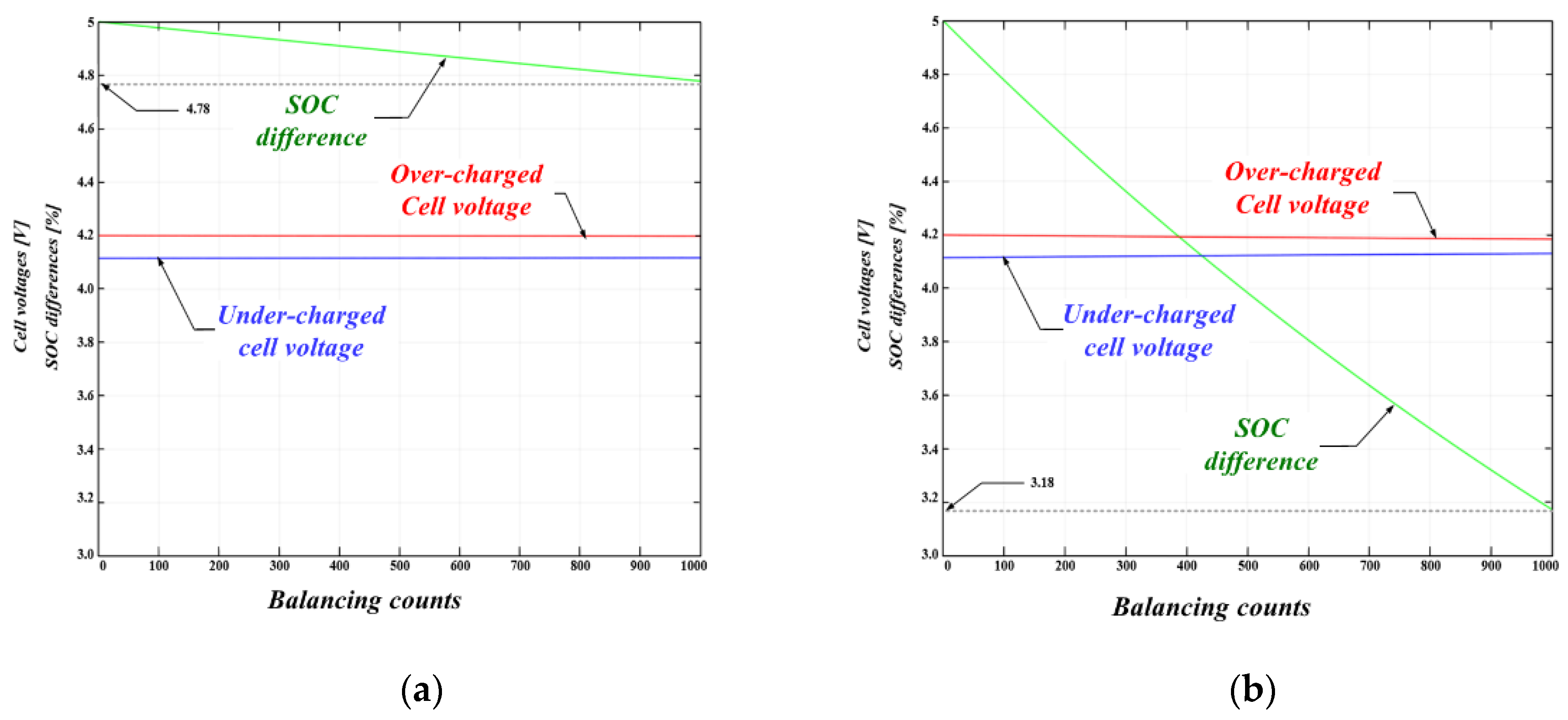
Figure 6 and
Table 5 show that the balancing differences are exponentially decreased and the balancing speed is not affected by the balancing capacitor values in the ACB method, respectively. However, the switching losses, which are not considered in this analysis, are affected by the cycle count, so that the switching frequency needs to be minimized to improve the efficiency.
4.3.2. Analysis of the PCB Circuit
The PCB method balances the SOC differences of the cells by dissipation of over-charged cell energy using the parallel-connected resistor. It shows more loss than the ACB method, but it is more widely used in industry due to its simple structure and excellent overall system stability.
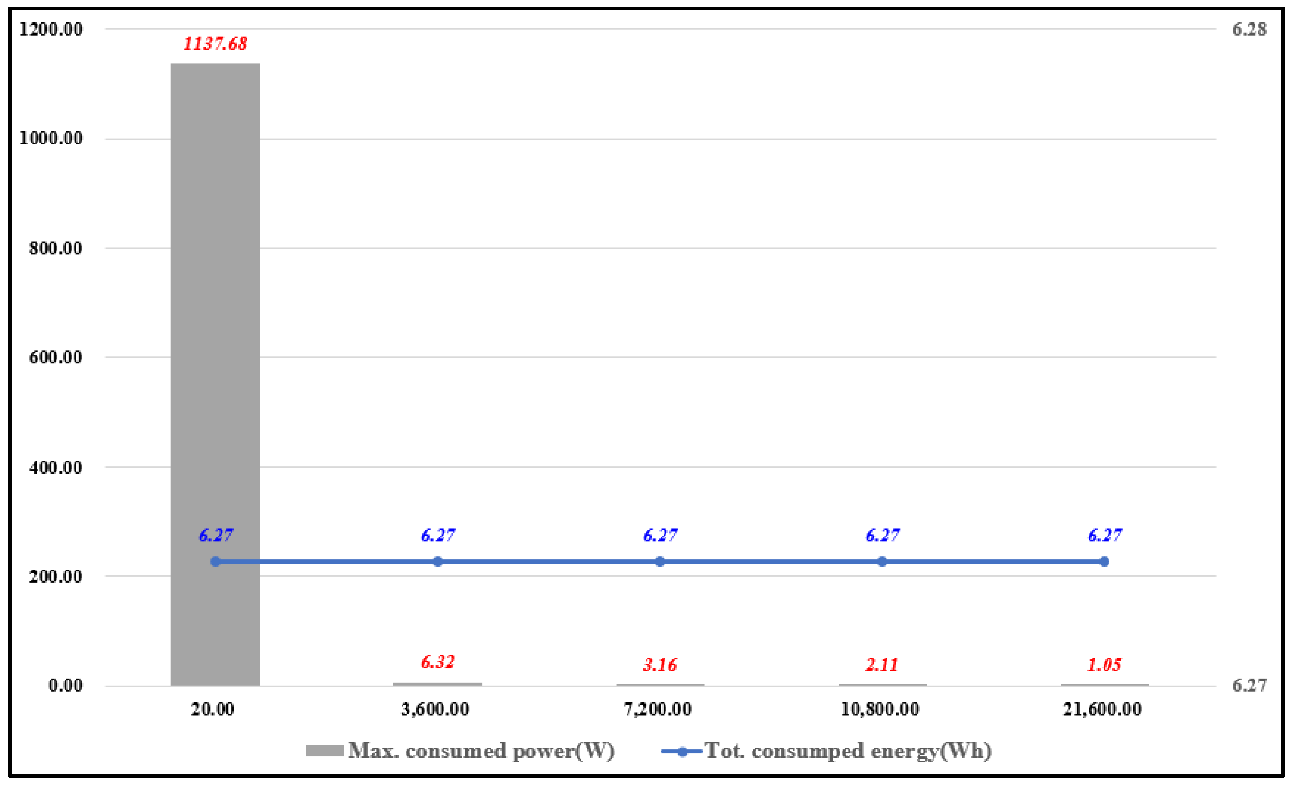
Figure 5b shows a shunting resistor-type PCB circuit that connects a “switch-resistance” configuration in parallel to each series cell. In this circuit, the required number of resistors and switches varies linearly with the configuration of the series cell. When “n” series cells are configured, “n” resistors and “n” unidirectional switches are required. In the case of the PCB circuit, the energy of the over-charged cell is consumed by the resistance until the SOC deviation reaches the normal range. Therefore, the consumed energy is not affected by the balancing time. However, the instantaneous amount of power consumed by the discharge resistor is changed depending on the discharge time. The shorter the discharge time, the greater the maximum power consumed by the discharge resistor. This results in an increase in the size of the discharge resistor.
Table 6 shows the maximum consumed power, total energy loss and balancing current value of each cell according to balancing time when the PCB method is applied. The balancing resistor, the maximum consumed power and the balancing current per cell were calculated using Equations (6) and (7). Samsung SDI 21700-30T lithium-ion rechargeable cells were used in the analysis. The specifications of the cell are shown in
Table 7 and the power and energy loss comparisons with balancing time is shown in
Figure 7.
Average balancing current value:
Balancing resistor value:
4.3.3. Experimental Results and Comparisons
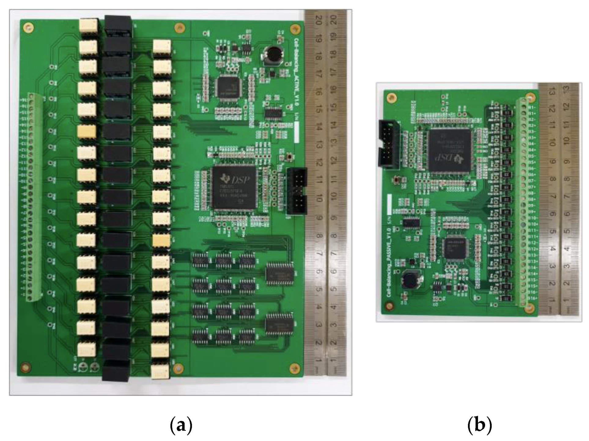
To verify the characteristic differences between the two methods analyzed above, prototypes of the ACB circuit and the PCB circuit were built and tested. The experimental prototypes were designed based on the balancing conditions shown in
Table 4.
Table 8 shows the experimental specifications, and the devices used in the experiments are shown in
Table 9. Each cell-balancing method was designed with reference to the maximum balancing time being less than 7 h, which is the minimum time for which a railroad vehicle is stationed in the depot. The single-switched capacitor circuit in the ACB method and the switched shunting resistor circuit in the PCB method were applied to compare the cell-balancing methods.
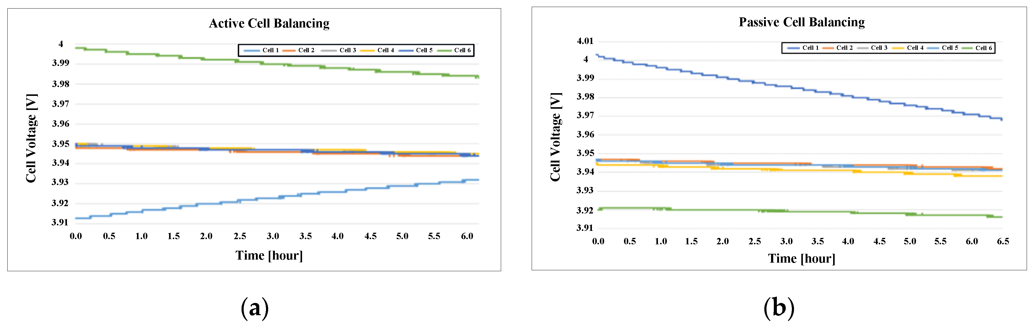
Figure 8 and
Figure 9 show the experimental prototypes and experimental waveforms, respectively. The experimental prototypes were designed considering the module structure described in
Table 4 and flexibility of experimental conditions. The consumed energy in
Table 10 was calculated by Equation (10) from the total voltage difference of battery module described in
Table 11, and the equivalent battery capacitance C
eq was assumed as 7200 F. V
pre and V
post represent the voltage before cell-balancing and the voltage after cell-balancing, respectively.
In the ACB method of charging the under-charged cell using the energy of the over-charged cell, the under-charged cell voltage has been increased, and in the PCB method of performing cell-balancing by dissipating the energy of the over-charged cell, the under-charged cell voltage showed a slight decrease due to self-discharge at almost the same level.
5. Conclusions
The design considerations for ESS in railroad propulsion systems were reviewed in this paper. It has been found that the system size can be significantly reduced if the nominal voltage level of the ESS is designed to be less than 1000 V. However, the voltage of the ESS affects the output power of the railroad vehicle and the composition of the peripheral power converters, so a comprehensive review was necessary. In the case of the cell-balancing method, it is advantageous to perform cell-balancing while the vehicle is stationed at the depot, in consideration of the operating characteristics of railroad vehicles that require continuous charging and discharging of the ESS during operation. In the cell-balancing circuit, we have to consider the trade-off energy efficiency and volume under the operation condition. ACB can be preferred when the SOC difference is large and high balancing efficiency is required in the entire range of the SOC. On the other hand, passive cell-balancing has advantages when space is constrained in the battery system and the depth of discharge (DoD) is small—in other words, SOC difference is small. Therefore, passive cell-balancing can be preferred to active cell-balancing in a hybrid railroad vehicle. Thus, adopting the PCB method in the ESS for railroad vehicles is a better option to enhance the system’s reliability and reduce the size of the ESS.
ESSs applied to railroad vehicles usually have high-voltage and large-capacity specifications, so the initial production and maintenance costs are high. Therefore, further research on the BMS, considering the life cycles of the batteries, is needed in order to reduce the maintenance cost.
Author Contributions
I.-H.C. contributed to the main idea of this article, formal analysis and wrote the paper. B.-H.L. provided the experimental data and validation. S.-Y.P. and J.-H.K. revised the paper critically, J.-H.R. contributed to conceptualization. All authors have read and agreed to the published version of the manuscript.
Funding
This research was supported by a grant (20RTRP-B146008-03) “Development of Optimized Railway Vehicle Propulsion System using Hydrogen Fuel Cell Hybrid Power System (1.2 MW or more) from the Ministry of Land, Infrastructure and Transport, South Korea.
Conflicts of Interest
The authors declare no conflict of interest.
References
- Edenhofer, O.; Pichs-Madruga, R.; Sokona, Y.; Minx, J.C.; Farahani, E.; Susanne, K. Climate Change 2014: Mitigation of Climate Change; Cambridge University Press: Cambridge, UK, 2014. [Google Scholar] [CrossRef]
- Chéron, C.; Walter, M.; Sandor, J.; Wiebe, E. ERRAC—European Railway Energyroadmap: Towards 2030. In Proceedings of the 9th World Congress on Railway Research—WCRR2011, Lille, France, 22–26 May 2011. [Google Scholar]
- Woo, J.H.; Han, J.H.; Lee, J. A Study on Enhancing Regenerative Energy Efficiency for Urban Railway Vehicles by Applying Energy Storage System. Trans. Korean Inst. Electr. Eng. 2014, 63, 1306–1311. [Google Scholar] [CrossRef][Green Version]
- Frilli, A.; Meli, E.; Nocciolini, D.; Pugi, L.; Rindi, A. Energetic optimization of regenerative braking for high speed railway system. Energy Convers. Manag. 2016, 129, 200–215. [Google Scholar] [CrossRef]
- Ceraolo, M.; Lutzemberger, G. Stationary and on-board storage systems to enhance energy and cost efficiency of tramways. J. Power Source 2014, 264, 128–139. [Google Scholar] [CrossRef]
- Zhang, W.; Li, J.; Xu, L.; Ouyang, M. Optimization for a fuel cell/battery/capacity tram with equivalent consumption minimization strategy. Energy Convers. Manag. 2017, 134, 59–69. [Google Scholar] [CrossRef]
- Berger, R. Development of Business Cases for Fuel Cells and Hydrogen Applications for Regions and Cities. In Hydrogen Injection into the Natural Gas Grid; Roland Berger: Munich, Germany, 2017. [Google Scholar]
- MYoussef, Z.; Orabi, M.; Tarbouchi, M. Design of an efficient multilevel inverter for a 1500V railway propulsion system applications. In Proceedings of the IEEE Applied Power Electronics Conference and Exposition, Charlotte, NC, USA, 15–19 March 2015. [Google Scholar]
- International Electrotechnical Commission. Effects of Current on Human Beings and Livestock, CEI/IEC 60479-1: General Aspects, 5th ed.; International Electrotechnical Commission: Geneva, Switzerland, 2016. [Google Scholar]
- Ronanki, D.; Singh, S.A.; Williamson, S.S. Comprehensive Topological Overview of Rolling Stock Architectures and Recent Trends in Electric Railway Traction Systems. IEEE Trans. Transp. Electrif. 2017, 3, 724–738. [Google Scholar] [CrossRef]
- Go, H.S.; Cho, I.H.; Kim, G.D.; Kim, C.H. Reduction of Electricity Prices Using the Train to Grid (T2G) System in Urban Railway. Energies 2018, 11, 501. [Google Scholar] [CrossRef]
- Reichert, M.; Andre, D.; Rosmann, A.; Janssen, P.; Bremes, H.-G.; Sauer, D.U.; Passerini, S.; Winter, M. Influence of relaxation time on the lifetime of commercial lithium-ion cells. J. Power Sources 2013, 239, 45–53. [Google Scholar] [CrossRef]
- Pham, V.L.; Duong, V.T.; Choi, W.J. A Low Cost and Fast Cell-to-Cell Balancing Circuit for Lithium-Ion Battery Strings. Electronics 2020, 9, 248. [Google Scholar] [CrossRef]
- Wu, S.T.; Chang, Y.N.; Chang, C.Y.; Cheng, Y.T. A Fast Charging Balancing Circuit for LiFePO4 Battery. Electronics 2019, 8, 1144. [Google Scholar] [CrossRef]
- Welsh, J.D. A Comparison of Active and Passive Cell Balancing Techniques for Series/Parallel Battery Packs. Master’s Thesis, Ohio State University, Columbus, OH, USA, 2009. [Google Scholar]
- Moghaddam, A.F.; den Bossche, A.V. A Single Transformer for Active Cell Equalization Method of Lithium-Ion Batteries with Two Times Fewer Secondaries than Cells. Electronics 2019, 8, 951. [Google Scholar] [CrossRef]
- Daowd, M.; Antoine, M.; Omar, N.; den Bossche, P.V.; Mierlo, J.V. Single Switched Capacitor Battery Balancing System Enhancements. Energies 2013, 6, 2149–2174. [Google Scholar] [CrossRef]
- Moghaddam, A.F.; den Bossche, A.V. An Efficient Equalizing Method for Lithium-Ion Batteries Based on Coupled Inductor Balancing. Electronics 2019, 8, 136. [Google Scholar] [CrossRef]
- Cho, I.H.; Kim, D.Y.; Lee, B.H. Research on Technical Characteristics of Battery Management System for Railway Systems. J. Korean Soc. Railw. 2018, 21, 882–891. [Google Scholar] [CrossRef]
Figure 1.
System configuration of the fuel-cell hybrid railroad vehicle propulsion system.
Figure 1.
System configuration of the fuel-cell hybrid railroad vehicle propulsion system.
Figure 2.
Power transmission mechanisms according to the driving pattern: (a) powering; (b) coasting; (c) braking.
Figure 2.
Power transmission mechanisms according to the driving pattern: (a) powering; (b) coasting; (c) braking.
Figure 3.
System configuration of a battery pack and a battery rack: (a) battery pack; (b) battery rack.
Figure 3.
System configuration of a battery pack and a battery rack: (a) battery pack; (b) battery rack.
Figure 4.
Comparisons of the battery pack components depending on voltage ratings: (a) fuse list; (b) contactor list.
Figure 4.
Comparisons of the battery pack components depending on voltage ratings: (a) fuse list; (b) contactor list.
Figure 5.
Schematic of the cell-balancing circuits: (a) the ACB circuit; (b) the PCB circuit.
Figure 5.
Schematic of the cell-balancing circuits: (a) the ACB circuit; (b) the PCB circuit.
Figure 6.
Trends of the cell voltages and the SOC differences with 1000 balancing cycles: (a) 100 mF balancing capacitor; (b) 1 F balancing capacitor.
Figure 6.
Trends of the cell voltages and the SOC differences with 1000 balancing cycles: (a) 100 mF balancing capacitor; (b) 1 F balancing capacitor.
Figure 7.
Power and energy loss comparisons with balancing time in the PCB method.
Figure 7.
Power and energy loss comparisons with balancing time in the PCB method.
Figure 8.
Experimental cell-balancing circuit prototype: (a) the ACB circuit; (b) the PCB circuit.
Figure 8.
Experimental cell-balancing circuit prototype: (a) the ACB circuit; (b) the PCB circuit.
Figure 9.
Experimental waveforms according to cell-balancing method: (a) the ACB method; (b) the PCB method.
Figure 9.
Experimental waveforms according to cell-balancing method: (a) the ACB method; (b) the PCB method.
Table 1.
Specifications for the propulsion system of fuel-cell powered railroad vehicle.
Table 1.
Specifications for the propulsion system of fuel-cell powered railroad vehicle.
| Description | Values | Remarks |
|---|
| Maximum output power | 1.3 MW | Total required power for two-car sets |
| Fuel-cell output power | 400 kW | 200 kW, 2 EA |
| Battery output power | 900 kW | 450 kW, 2 EA |
| Range | 600 km | - |
| Maximum speed | 140 km/h | - |
| Battery pack voltage level | 1500 V | DC heavy rail traction system standard |
Table 2.
Specifications for the propulsion system of fuel-cell powered railroad vehicle.
Table 2.
Specifications for the propulsion system of fuel-cell powered railroad vehicle.
| Class | Nominal Voltage (Un) | Electrical Insulation |
|---|
| AC (V) | DC (V) |
|---|
| Class A | Un ≤ 30 | Un ≤ 60 | Not regulated |
| Class B | 30 < Un ≤ 1000 | 60 < Un ≤ 1500 | Double insulation |
| Otherwise | Un > 1000 | Un > 1500 | Double insulation and protective ground |
Table 3.
Voltage insulation test for railroad applications.
Table 3.
Voltage insulation test for railroad applications.
| Definition | Nominal Voltage (Un) |
|---|
| ≤60 | 36~60 | 60~300 | 300~660 | 660~1200 | 1200~10,000 |
|---|
| Test voltage between each circuit and other circuit grounds | 750 | 1000 | 1500 | 2500 | 2 Un + 1500 | 2 Un + 2000 |
Table 4.
Cell-balancing criteria for the battery module.
Table 4.
Cell-balancing criteria for the battery module.
| Item | Definition |
|---|
| Battery cell specifications | 2.5 V~4.2 V, 3.6 V rated, 8 Wh |
| Battery module specifications | 14S36P, 4.2 kWh |
| Cell-balancing initiated condition | Cell SOC difference 5% |
| Cell-balancing terminated condition | Cell SOC difference 3% |
| Maximum cell-balancing time | 8 h |
Table 5.
Design and analysis of the ACB circuit.
Table 5.
Design and analysis of the ACB circuit.
| Definition | 100 mF
Balancing Capacitor | 1 F
Balancing Capacitor |
|---|
| Initial balancing condition | Over-charged cell voltage: 4.2 V
Under-charged cell voltage: 4.12 V
SOC difference: 5% |
| Battery cell capacitance (CBatt) | 4408 F (Samsung SDI, 21700-30T Cell) |
| Equivalent series resistance (ESR) | 0.001 Ohm | 0.001 Ohm |
| Minimum switching frequency | 500 Hz | 50 Hz |
SOC differences after 1000 switching cycles
(total balancing time) | 4.78% (2 s) | 3.18% (20 s) |
| SOC differences after 20 s (cycles) | 4.36% (10,000 cycles) | 3.18% (1000 cycles) |
Table 6.
Design and analysis of the PCB circuit for the 14S36P battery module.
Table 6.
Design and analysis of the PCB circuit for the 14S36P battery module.
| Definition | 20 s
Balancing | 3600 s
Balancing | 7200 s
Balancing | 10800 s
Balancing |
|---|
| Balancing time (TBal) (s) | 20 | 3600 | 7200 | 10,800 |
| Parallel cell count (EA) | 36 | 36 | 36 | 36 |
| Max. consumed power (W) | 1137 | 6.32 | 3.16 | 2.09 |
| Total energy loss (Wh) | 6.27 | 6.27 | 6.27 | 6.27 |
| Peak balancing current for a cell (A) | 7.52 | 0.04 | 0.02 | 0.01 |
Table 7.
Specifications of the battery used in the analysis.
Table 7.
Specifications of the battery used in the analysis.
| Battery Cell | Rated Voltage | Rated Capacity | Over-Charged Cell Voltage | Under-Charged Cell Voltage |
|---|
21700-30T
(Samsung SDI, Korea) | 3.6 V | 3 Ah | 4.2 V | 4.12 V |
Table 8.
Experimental specifications for the PCB method with HY18650.
Table 8.
Experimental specifications for the PCB method with HY18650.
| Definition | Description |
|---|
| Battery model | HY18650 |
| Battery cell specification | 2000 mAh (3.7 V, 7.4 Wh) |
| Battery module specification | 6S1P |
| Cell-balancing initiated condition | ΔCell SOC = 5% |
| Cell-balancing terminated condition | ΔCell SOC = 3% |
Table 9.
Component specifications used in the experiment for the ACB and PCB methods.
Table 9.
Component specifications used in the experiment for the ACB and PCB methods.
| Definition | ACB Method | PCB Method | Note |
|---|
| Switches | (Nexperia) 2N7002BK, 4EA | (Nexperia) 2N7002BK, 1EA | For a cell |
| Resistor (ohm) | - | 195 | For a cell |
| Capacitor (uF) | 10 | - | For a cell |
| System size (mm2) | 387.6 | 9.3 | For a cell |
Table 10.
Comparison between the ACB method and the PCB method by experimental results.
Table 10.
Comparison between the ACB method and the PCB method by experimental results.
| Definition | ACB Method | PCB Method | Note |
|---|
| Balancing time | 6 h (21600 s) | 6 h 30 min (23400 s) | - |
Cell voltage of over charged cell (V)
(Before balancing/after balancing) | 3.998/3.983 | 4.003/3.968 | - |
Cell voltage of under charged cell (V)
(Before balancing/after balancing) | 3.913/3.932 | 3.92/3.916 | - |
| Consumed energy (Wh) | 0.129 | 0.476 | 3.7 times differences |
Table 11.
Battery cells voltage variation under the ACB method and the PCB method.
Table 11.
Battery cells voltage variation under the ACB method and the PCB method.
| Definition | ACB Method | PCB Method |
|---|
| Pre | Post | Pre | Post |
|---|
| Cell 1 | 3.913 | 3.932 | 4.003 | 3.968 |
| Cell 2 | 3.949 | 3.944 | 3.947 | 3.942 |
| Cell 3 | 3.95 | 3.945 | 3.946 | 3.941 |
| Cell 4 | 3.95 | 3.945 | 3.944 | 3.941 |
| Cell 5 | 3.949 | 3.944 | 3.946 | 3.941 |
| Cell 6 | 3.998 | 3.983 | 3.92 | 3.916 |
© 2020 by the authors. Licensee MDPI, Basel, Switzerland. This article is an open access article distributed under the terms and conditions of the Creative Commons Attribution (CC BY) license (http://creativecommons.org/licenses/by/4.0/).


