Abstract
In considering projections that flooding will increase in the future years due to factors such as climate change and urbanization, the need for dependable and accurate water sensors systems is greater than ever. In this study, the performance of four different water level sensors, including ultrasonic, infrared (IR), and pressure sensors, is analyzed based on innovative characterization and comparative analysis, to determine whether or not these sensors have the ability to detect rising water levels and flash floods at an earlier stage under different conditions. During our exhaustive tests, we subjected the device to a variety of conditions, including clean and contaminated water, light and darkness, and an analogue connection to a display. When it came to monitoring water levels, the ultrasonic sensors stood out because of their remarkable precision and consistency. To address this issue, this study provides a novel and comparative examination of four water level sensors to determine which is the most effective and cost-effective in detecting floods and water level fluctuations. The IR sensor delivered accurate findings; however, it demonstrated some degree of variability throughout the course of the experiment. In addition, the results of our research show that the pressure sensor is a legitimate alternative to ultrasonic sensors. This presents a possibility that is more advantageous financially when it comes to the development of effective water level monitoring systems. The findings of this study are extremely helpful in improving the dependability and accuracy of flood detection systems and, eventually, in lessening the devastation caused by natural catastrophes.
1. Introduction
1.1. Background
In recent years, especially in 2019 and 2020, Jordan and Downtown Amman—a low region surrounded by Amman’s mountains that serves as an outlet for water flow through precast boxes from the city—witnessed heavy rainfall and sudden flash floods, which caused losses in merchandise, infrastructure, and human lives. In 2019, two hundred clothing stores were affected, causing losses totaling five million JOD [1,2]. On the 8th and 9th January 2020, rainfall caused floods in Downtown Amman and the 7th Circle that affected one hundred stores, and the Great Amman Municipality stated that there would be no indemnification for traders that year [3]. These and other recent floods were also responsible for losses of life and property destruction. Other cities in Jordan suffered floods, such as Irbid and Al-Mafraq, where, very recently, an eleven-year-old child was found drowned in the Dlail Valley stream close to the Al-Khaldia area, which happened due to a flash flood created by rainfall [4]. There was also the Dead Sea disaster on the 25th of October 2018, in which twenty-one were killed and forty-three were injured, most of whom were young children on a school trip. In addition to Jordan, other countries around the globe witnessed flash floods in recent years, such as China, Brazil, Germany, and the United Kingdom. Disasters such as these motivate officials and professionals to look for solutions to minimize the losses of both human life and material damage. Solutions such as warning systems, which use water level sensors as their main component, are highly effective and widespread. Many of these systems use complicated and somewhat expensive, such as the MB7386 HRXL ultrasonic sensor (USD 137), which was employed in an energy-efficient warning system for real-time monitoring. The project used dual microcontrollers for low-power consumption [5]. Another sensor is the tough sonic remote sensor (USD 500), which was utilized in an early warning system in Colima, Mexico, as part of a network of sensors to predict flash floods and alert locals to take precautions and evacuate in time [6]. Sensors such as these could be replaced with simple and more affordable alternatives, such as the sensors characterized in this paper, and produce the same results, with prices that do not exceed USD 15.
1.2. Literature Review
Except for the pressure sensor, the other sensors investigated in this study were used in many research studies focusing on water level measurements. In this section, a few of these studies are listed, as well as studies regarding other applications. Alasali et al. [7] used an off-the-shelf ultrasonic sensor (HC-SR04) in a real-time early-warning system based on an artificial neural network and golden ratio optimization that was employed to predict flash floods to alert decision-makers and users. The system was intended for installation in the center of Amman. A system that utilized the same water level sensor in real time to monitor and control floods was described by Hajjaj et al. [8] The arrangement consisted of a flood gate that automatically opens and closes in accordance with the water level. The data were collected using Raspberry PI and sent via a developed program to a cloud using internet of things (IoT) technology. The HC-SR04 was also used in a setup that measured the water level and sent a message indicating the level of danger. The sensor was used with the wireless fidelity (Wi-Fi) module ESP8266-12E and a buzzer communication media [9]. The research that used the HC-SR04 amongst other sensors in IoT-controlled water storage tanks was surveyed by Jan et al. [10], where they focused on monitoring the level of water and water leakage in smart water tanks that are used for water storage in rural regions. The sensor was also used for other applications, such as river water level measurements [11].
The JSN-SR04T’s performance was investigated by Andang et al. [12] for the detection of flood elevation in the Tasikmalaya River, Indonesia, under various conditions. The data were processed using a microcontroller and the results were compared to the sensor’s datasheet information. It was concluded that the sensor has a resolution of 0.5 cm, which was considered very high. The same component was paired with a SIM 900A by Dswilan et al. [13] and employed to detect floods and collect data. The sensor was effective for distances in the range of 20–600 cm producing a sensitivity of 5.03 mV/cm. A device was introduced that was constructed out of the JSN-SR04T, a pipe, and a microcontroller to read the water levels in open channels [14]. The proposed system was designed to overcome the difficulties that are present in these channels, such as the formation of waves, floating objects, and rough structures. Another instrument that was placed underwater to detect approaching floating objects was presented by Bakar et al. [15], where a waterproof ultrasonic sensor combined with an Arduino UNO and light emitting diodes (LEDs) were used to determine the location of an object.
The infrared (IR) sensor was used little in water level measurements or flash flood warning systems. However, reports of the application of this component are very common in the literature, and the following describes several related articles. The GP2Y0A02YK0F sensor was exploited by Mustapha et al. [16] to develop a system that helps the elderly and people with vision defects to detect nearby objects. Different tests were performed for the sensor, such as voltage versus distance, accuracy, and voltage versus angle. Since the IR sensor has a nonlinear voltage–distance relation, a fitting curve was used to linearize the results. The system is suitable for different materials and colors. The same sensor was characterized by Sobres et al. [17], where the distance between the sensor and a white-colored object was measured for ten seconds. The distance was accurate with an acceptable mean value and standard deviation, except for 10% of the readings, in which the measured distance was inaccurate. This was found to be a periodic occurrence and was filtered out by using the median technique, which improved both the median value and the deviation. The voltage at different distances was measured versus time, where the voltage–distance relationship showed nonlinearity, while the voltage–inverse distance showed linearity in some regions. In another work, the GP2Y0A02YK0F was modelled by using the piecewise Newton polynomials with the vertex determination method to generate a nonlinear model, which was successful in minimizing the Ruge’s effect that appears in polynomial-based modelling [18]. The mean square error was as low as 0.001 and the percentage error was 2.38%. The same sensor was also used as part of a smart data-gathering system that functioned as a wireless sensor network, in which several parameters, including water level, were monitored in aquaculture tanks [19,20].
The use of the MS5540C has been described little in the literature; however, it is worth mentioning a few articles in which it was utilized for pressure, temperature, and humidity measurements, among other applications. For instance, a system was introduced in which a cell phone was located horizontally as well as vertically [21]. Using this system, the floor’s position in a building can be determined depending on barometric measurements. The same sensor was used amongst other environmental sensors in a project that described the assessment and enhancement of a gas-phase sensor system, which was used to collect data for ambient environmental conditions [22]. The sensor also has medical applications. For example, it was used for measuring human blood pressure in the attempt to monitor wounds and their conditions in the human body. However, it is invasive to the human body and cannot be used remotely [23]. Chan et al. [24] utilized the ms5540c in a context engine system for barometric, temperature, and humidity measurements. A simultaneous localization and mapping system used this pressure sensor for barometric measurements to determine the altitude of a drone sent to locations that are difficult to reach via the global positioning system [25]. The barometer was also employed in a wireless network-based indoor tracking system for altitude and environmental readings [26].
In addition to the sensors tested in this paper, there are many other water and liquid level measurement techniques, some of which are mentioned next. The polymer optical fiber sensors, which are compact, have high flexibility, and are resistant to electromagnetic interference [27]. The working principle is that the temperature of the sensing fiber differs with respect to the environment surrounding the fiber. Thus, the part of the fiber that is placed under the liquid has a different temperature than the part placed above the liquid, which indicates the water level [28]. Another type is the capacitive sensor, where the capacitance changes between an electrode and a metal tank with the change in water level. The data are provided by a circuit in the form of voltage or current [29]. An example of capacitive-based sensors is presented in [30], in which Paczesny et al. introduced an inkjet-printed liquid level capacitive sensor. Radar sensors are also used in measuring liquid levels and have a working principle similar to that of ultrasonic sensors, where a radio frequency signal is sent through air until it hits a surface and bounces back to the radar. The time of flight is measured and the distance is calculated. This sensor was employed in projects such as the River Information Services system presented in [31].
1.3. Contributions
In terms of reliability, this article investigates the efficiency of a low-cost sensor for water level detection to overcome significant technological limitations for developing water level and flash flood monitoring systems. As a result, the following are the article’s main contributions:
- Since the frequency and severity of floods continue to rise, the need for early detection and rapid warning systems is more pressing than ever. In response, this study offers a novel comparative analysis of four water level sensors in order to determine the most effective and cost-effective method for monitoring floods and water level fluctuations. The four sensors under consideration were not previously referred to in the same study at once due to the differences in their natures and working principles (except for the two ultrasonic sensors). The HC-SR04 and JSN-SR04T ultrasonic sensors, the GP2Y0A02YK0F infrared sensor, and the MS5540C pressure sensor were tested under a variety of experimental settings, including different types of water, illumination, and analogue testing;
- The measurements were obtained electronically (using a microprocessor) and directly (analogue measurements) and compared to the information provided by their respective datasheets. Furthermore, the effective angle for the ultrasonic sensors was tested, and it was observed how far from the zero angle an object can be placed while obtaining accurate distance readings. The pressure sensor was not used frequently in water level measurements; in this study, it was tested under different water conditions. This work therefore offers an addition to the limited existing literature on the subject. Moreover, as far as our team knows, water level measurements considering water purity using the sensors described in this paper were not undertaken previously. Regarding the IR sensor’s results, they might indicate that the sensor is not the best choice for water level measurements, or that they need further processing, since the voltage–distance relationship for the device is not linear and because of the nature of light and water. A typical process was followed to obtain the readings from the sensors by using a microprocessor and a computer to control the sensors and display the results. Another approach used was to acquire the data directly from the output pin of the sensor by a monitor or a multimeter. In both cases, the outcome was compared to the information provided by their respective datasheets. This study also serves as an easy source of information regarding the reported sensors, their theoretical basis, and the setup needed to run them.
2. Materials and Methods
To reduce the risks of flash floods and the losses they cause, several early warning systems were designed for use nationally and internationally. The main building block of these systems is a water level sensor. There are various types of water level sensors that use different technologies, and their prices vary from very high to very low. Some of these sensors are characterized and evaluated in this project. These sensors include two ultrasonic sensors: the HC-SR04, which is referred to as the ultrasonic sensor 1 (USS1), and the JSN-SR04T, which is referred to as the ultrasonic sensor 2 (USS2). They also include an IR sensor, GP2Y0A02YK0F, and a pressure sensor, MS5540C. The sensors were selected because they are widely available and low-priced. Some of them have fairly accurate readings, and their experimental setup is quite simple. The following is a description of the sensors, their theoretical basis and function, and their datasheet information.
2.1. Components
2.1.1. HC-SR04 (Ultrasonic Sensor 1, USS1)
Ultrasonic sensors are commonly used for water level measurement. The HC-SR04, which costs around USD 3 and is manufactured by OSEPP Electronics LTD (Tempe, AZ, USA), consists of a transmitter that sends the ultrasonic soundwave and a receiver that catches the signal after it bounces back from a surface. The sensor needs an input voltage of 5 V for at least 10 µs to create a pulse of 8 cycles with a frequency of 40 KHz; when the returned signal is received, it sets an ECHO pin to HIGH at 5 V with a pulse width proportional to the distance. The width of the pulse is the time needed for the sound wave to travel. The distance x is calculated by applying the measured travel time and the speed of sound (340 m/s) to Equation (1) [32].
where x is the distance in cm, v is the speed of sound in m/s, and Δt is the pulse width in seconds. The 100 in the right side of Equation (1) is to transform the unit directly from meters to centimeters. An alternative expression to find the distance x is presented in Equation (2) [32]. Here, the pulse width must be the factor of microseconds to calculate the distance directly in centimeters. More specifications are shown in Table 1.

Table 1.
Datasheet information for the sensors under consideration.
2.1.2. JSN-SR04T (Ultrasonic Sensor 2, USS2)
The JSN-SR04T is made by James Electronics (Belmont, CA, USA) and costs around USD 1.5. Unlike the HC-SR04, this device utilizes only one transducer, which both sends and receives the ultrasonic wave. Its main parts are a waterproof transducer, a long probe, and an electronic circuit. This sensor is waterproof, small, and accurate, has high resolution, consumes a minimal amount of power, and has a variety of output modes. The JSN-SR04T’s specifications are shown in Table 1 [33]. Its working principle is similar to that of the HC-SR04, and the distance can be obtained using Equation (1) or Equation (2).
2.1.3. GP2Y0A02YK0F (IR Sensor)
The IR sensor used in this study is Sharp’s GP2Y0A02YK0F (Sakai, Japan), which costs about USD 12 and consists of an infrared light-emitting diode as a transmitter, a photosensitive detector as a receiver, and a signal processing circuit. This component produces an analogue output voltage that is proportional to the distance between the device and the detected object. If an optical filter is used, the recommended wavelength should be 850 ± 70 nm [34]. More specifications are shown in Table 1. This sensor uses the triangulation method, and therefore, it is not affected easily by the surrounding temperature or change in reflectivity, and thus provides accurate readings. The distance is measured in centimeters using Equation (3), where the output is read by a microcontroller ADC [34].
where is the output voltage in mV. This sensor is intended for measuring the distance between a solid object and the sensor’s receiver. This project also tested the distance for measuring water levels.
2.1.4. MS5540C The Pressure Sensor
The pressure sensor under consideration in this article is the vented gauge pressure sensor, MS5540C, which is manufactured by TE Connectivity (Schaffhausen, Switzerland) and costs around USD 10. It utilizes a piezoresistive pressure sensor and provides pressure- and temperature-related analogue output voltage. The voltage is converted to a 16-bit data word via an analogue-to-digital converter. This device has low power and voltage requirements, and some of its characteristics are listed in Table 1. Other technical data that are not mentioned in the table are as follows: the range of pressure measurements is from 10 mbar to 1100 mbar, the resolution is 0.1 mbar, and the pressure accuracy is temperature-dependent, namely ±1 mbar for 0 °C to 50 °C. Furthermore, the response time is 35 ms, and finally, the stability is −1 mbar/year [35]. The sensor measures the pressure between a reference point (1 cm below the surface) at a certain level and takes the difference between the two values to convert the result to water level. A piezoresistive pressure sensor consists of a strain gauge made of either metal or a semiconductor, which changes its resistance when stretched, in this case due to pressure. By increasing the applied force, the gauge stretches and the cross-sectional area decreases, causing the resistance to increase. Another factor is the resistivity of the material, which increases when the material is stretched. Equation (4) shows the relation between the resistance, cross-sectional area, resistivity, and length.
where R is the resistance (Ω), ρ is the resistivity (Ω/m), L is length (m), and A is the cross-sectional area (m2). The strain gauge can be connected to a Wheatstone bridge as one of the resistors. When there is no change in the resistance of the strain gauge, the bridge is balanced and the output voltage is 0 V. As the resistance of the strain gauge increases, the output voltage increases. In this work, the sensor is used for water level measurements. The height–pressure–density relation is given in Equation (5).
where P is the pressure, ρ is the density of water and equals 1000 Kg/m3, h is the height of water (m), and g is the acceleration of gravity and equals 9.8 m/s2.
2.2. Methodology
The environment in which the sensor is placed can affect its reliability and efficiency. Thus, different sensors with different natures and working principles should be tested and compared to determine which is more suitable for a given condition. The following is a description of the experiments that were performed on the four sensors, with the consideration that not all tests can be applied to all sensors due to their category and structure:
- The sensors were tested for water level measurements during day and night for pure and impure water. The pure water (conductivity ~ 300 µs/cm) was clean and fresh without any impurities, while the impure water was prepared in this study by adding 500 g of mud to 3 litters of water. The sensors were fixed on top of a water tank to measure the water level and were controlled by an Arduino, which also interfaced the sensor with a computer, where the collected data were saved. These results were taken for different water heights. USS1, USS2, and the IR sensor were considered for this test, while the pressure sensor needed a slightly different setup, since it needed to be placed under the surface of the water, because the pressure on the gauge of the sensor varied with the depth of the water. Figure 1a shows the setup, and Figure 1b shows the actual setup. The setup in Figure 1b shows an Arduino that instructed the sensor to send a signal (sound or light) towards the water surface and receive it after it bounced back. The computer ran the Arduino and collected the data;
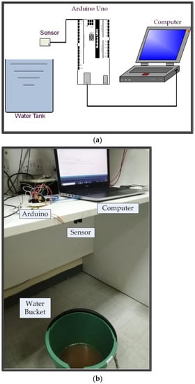 Figure 1. (a) A general setup for the water level measurements. (b) Actual setup for the water level measurements.
- The same arrangement used in the first step was used to measure the distance versus time for USS1, USS2, and IR sensors to verify the stability of the readings during a time interval. The readings were obtained for both water and hard surface as an object;
- The performance and accuracy of the USS1 and USS2 were tested by measuring the pulse width of the echo signal that bounced back from a hard surface and returned to the sensors’ receiver. The echo pin of the sensors was connected directly to an oscilloscope to monitor the signal. By applying the pulse width Δt to Equation (1) or Equation (2), the distance was obtained and compared to the actual value. A picture of the setup is shown in Figure 2;
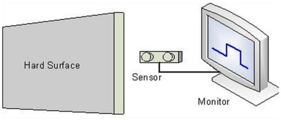
Figure 2.
Configuration of the setup used to measure the distance manually.
- The measuring angle was obtained for the ultrasonic sensors and compared to the data provided by their respective manuals. The setup was the same as in Figure 1, but the signal bounced off a hard object instead of the water level. Furthermore, a protractor with an extension that pointed in the direction of the object was used, while the sensor sat exactly at zero angles at the center of the protractor. A photograph of the setup using the USS2 sensor is shown in Figure 3;
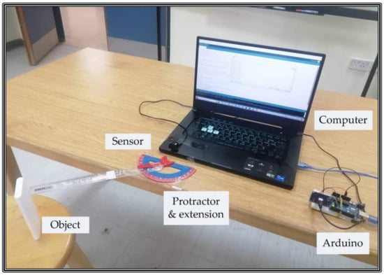
Figure 3.
Measuring the effective angle for the ultrasonic sensor.
- An experiment to realize the working principle of the IR sensor as well as to investigate its accuracy was performed by measuring the distance manually. The voltage at the output pin was obtained by a voltage multimeter and applied to Equation (3) to find the distance between a solid object and the sensor;
- The pressure sensor was tested for water level measurements. The arrangement was similar to that in Figure 1, but instead of the sensor being above the water tank, the sensor was placed beneath the water surface. Figure 4 shows the experimental setup.
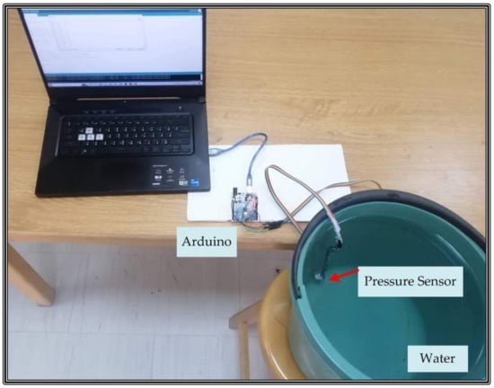 Figure 4. Water level measurement using the pressure sensor.
3. Results and Discussion
In this part, the results for the following experiments were summarized: single distance readings from water at different conditions, fixed distance measurements throughout a range of time, distance measurements from a hard surface, manual evaluation of the sensors, effective angle measurements, and water level measurements using the pressure sensor. The results clarify whether all the selected sensors were suitable for different environments. They show whether the IR sensor is suitable for water level measurements and whether the pressure sensor is a valid alternative for the same application. They also confirm some of the data provided by their datasheets and prove that the equations used to measure the distance, or the water level, were correct. Furthermore, they show whether changing the angle of the sensor affects the accuracy of the reading and by how much.
3.1. Fixed Distance from Water Readings at Different Conditions
The behavior of three sensors was examined by measuring the distance under different conditions considering pure water (clear fresh) and impure water during daylight and night. The sensors were tested at many distances that ranged between 50 cm and 90 cm. For pure water and at daylight, at shorter distances, the performances of the three sensors were fairly similar, with the USS1 having the highest error of 3%. At mid-range distance, all sensors performed well, while at longer distances, the IR sensor was far from accurate, with an error of 7%. The USS2 showed the most accurate results, with a maximum error of 1.5%. In the dark using pure water, the USS2 showed the best results again, with an error that did not exceed 0.7%, while the USS1 provided good results as well, with an error that was equal to or less than 1.8%. The IR sensor displayed inaccurate results, with an error that ranges between 1.9% and 6.4%. Flash flood water or water in the streets may include sediment or oil in urban areas. Therefore, to resemble real live conditions, the sensors were also tested for impure water, which, in this case, was prepared by adding 500 g of mud to 3 L of water. Directing the light to the mudded water enhanced the readings for the IR sensor, since the maximum recorded error was 5.9%, compared to around 7% for pure water. This is probably because light does not penetrate impure water as much as it penetrates pure water. The ultrasonic sensors’ readings were affected little by the impurity of the water and provided accurate results with the USS2 being slightly better. The IR sensor had the least accurate results because of the nature of light and water. Light can penetrate water, potentially affecting the distance readings. Furthermore, light refracts in water, which changes its direction and the angle at which it hits the surface of the detector, thus affecting the measured distance. However, in general, the sensor achieved higher accuracy in the case of impure water since the solid parts prevented the light from travelling deep under the water surface.
3.2. Fixed Distance-Versus-Time Tests
The sensor was placed above pure water at a fixed distance during daylight, and the readings were obtained every 1 s for half a minute. This was performed at different heights from the water surface. Figure 5 shows a plot of measured water level versus time at 78 cm for the ultrasonic sensors, which showed steady results, with the USS2 being slightly more accurate. The average of thirty readings (a reading every second) was found and the accuracy of the average was obtained using Equation (6). The USS1 readings during that time were 1 to 2 cm off, and an average of 76.9 cm with the accuracy of 98.5% was recorded. The USS2 readings were steady at 77 cm (1 cm off) with an average of 77 cm and an accuracy of 98.7%. The outcomes for other heights were quite similar for both sensors, with an accuracy as high as 99.2%. For impure water, the results are close to the ones in Figure 5.
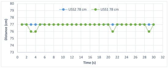
Figure 5.
Distance-versus-time measurements for ultrasonic sensor 1 (USS1) and ultrasonic sensor 2 (USS2) at 78 cm during daylight for pure water.
The same test was repeated for the IR sensor, but at different distances because the IR sensor is efficient at a different range and because the experiment was performed at a different time. At higher and shorter heights, the results are not quite accurate where an average of 62.8 cm was recorded at an actual height of 65 cm with an accuracy of 96.6%, and an average of 84 cm was obtained at an actual height of 91 cm with an accuracy of 92.4%. According to its datasheet, the IR sensor is effective between 20 cm and 150 cm; so, the closer the distance to the center of that range, the more accurate the results are. For example, at mid-range (around 75 cm), the IR sensor showed good results, as shown in Figure 6. The average of 30 readings was 75.8 cm with an accuracy of 98.9%. The Figure shows that the IR sensor needed fourteen seconds to provide steady and accurate results.
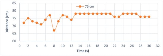
Figure 6.
Water level-versus-time measurements for the infrared (IR) sensor at 75 cm during daylight for pure water.
This procedure was repeated for impure water at shorter heights, such as 60 cm. The results are shown in Figure 7, where the average was 59.6 cm, with an accuracy of 99.3%. At higher and lower heights, the sensor showed similar results. Comparing the readings of the pure and impure water, the data were more accurate for the impure water, as was expected due to the reasons mentioned in Section 3.1
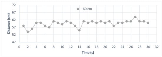
Figure 7.
Distance-versus-time measurements for the IR sensor at 60 cm during daylight and for impure water.
3.3. Distance from a Hard Surface
The fixed distance versus time experiment was repeated for a hard surface. The performances of the two ultrasonic sensors were checked by testing them at different distances where they provided very good results with an accuracy of more than 99.5%. An example is shown in Figure 8 at 105 cm with an average of 105.1 cm for thirty readings.
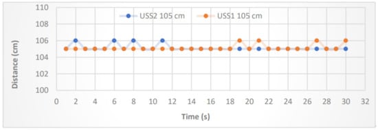
Figure 8.
Distance from a hard surface-versus-time measurements for USS1 and USS2 at 105 cm.
The same test was repeated for the IR sensor, in which thirty readings were obtained during half a minute, one reading every second. Again, the experiment was performed at different heights. For example, at 60 cm, all thirty readings were steady with a measured value of 61 cm, and the sensor achieved a very high accuracy of 98.3%, while at distances closer to the edges of the sensor’s effectiveness range, the readings were slightly less accurate and more fluctuating, with an accuracy of 97.9 at 40 cm and 95.5% at 80 cm. Figure 9 shows the results at 60 cm. Compared to the results in Figure 6 (water level results in daylight), it is obvious that the IR sensor was more effective in measuring the distance between the sensor and the hard object than measuring the distance between the sensor and the water surface. This was mainly due to the nature of light.
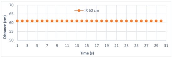
Figure 9.
Distance-versus-time measurement for the IR sensor at 60 cm from a hard surface.
3.4. Manual Distance Measurement for the Ultrasonic Sensors
To comprehend the working principle of the ultrasonic sensors and their theoretical basis, the distance was measured manually by monitoring the sonic signal after a round trip. The time the signal needed to travel from the sensor to a solid object and back after bouncing from the object was measured and applied to either Equation (1) or Equation (2) to calculate the distance. The image in Figure 10 shows a screen capture of an oscilloscope’s monitor obtained when the solid object was placed 132 cm away from the USS1. The yellow-colored signal is the trigger and the blue-colored signal is the retrieved sonic signal after a round trip. The pulse width of the captured signal Δt = 7.578 ms was applied to either Equation (1), with x = 129 cm, or Equation (2), with x = 130 cm. This example confirms the data provided by the sensor’s manual. The slight difference in the results was due to an error in the measurements and the equipment used. The process was repeated for several distances and provided similar results.
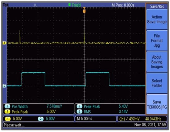
Figure 10.
Screen capture of a monitor showing the pulse that represents the sonic signal after a round trip at 132 cm.
The experiment was also performed using the USS2. An example at 94 cm is shown in Figure 11. For our example, Δt = 5.341 ms was applied to Equations (1) and (2) to calculate the distance x = 90.8 cm from Equation (1) and x = 92.09 cm from Equation (2). Both sensors displayed accurate results in this experiment.
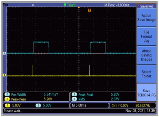
Figure 11.
Screen capture of a monitor displaying a sonic signal after a round trip at 94 cm using USS2.
3.5. Manual Distance Testing of the IR Sensor
To clarify how the output voltage of the IR sensor was transformed into the distance, the distance was calculated manually. A solid object was used in this experiment since the IR sensor proved to be more accurate in this case. The output voltage was measured directly from pin 1 of the sensor using a multimeter and applied to Equation (3). For example, at 40 cm, the measured output voltage was VO = 1460 mV and the distance was x = 41.11 cm with an accuracy of 97.2%. The readings for different distances were obtained and recorded fairly good results, except at 20 cm, where the accuracy was only 83.95% because this distance was at the edge of the measuring range of the IR sensor. Table 2 shows a few examples.

Table 2.
Calculated distance using the measured output voltage for the IR sensor.
3.6. Effective Angle Measurements
The effective angle of the ultrasonic sensor was measured by placing a solid object in front of the sensors with an angle. The distance was obtained at different angles from zero upwards. At less than 31°, the USS1 provided accurate readings, but at higher values, the obtained readings were inaccurate. This agrees with the datasheet’s information in [32]. The USS2 recorded an effective angle of 45°, which was much less than the value provided in Table 1. The angle measurement experiment could not be performed for the IR sensor, because light travels in straight lines, nor for the pressure sensor, because it needed to be placed below the water surface.
3.7. Water Level Measurements Using the Pressure-Sensor MS5540C
Our pressure sensor was not reported frequently in the literature, especially for water level measurements. This experiment shows the results for some of the water level readings using the MS5540C for different water conditions (pure water, impure water, and impure oily water). Impure water was considered because water in the streets can be muddy, oily, or both. The following content describes how the data were obtained: First, the sensor was placed 1 cm below the surface, which was the reference point. Next, to measure a certain water level, the sensor was positioned deeper in the water and the data were obtained at that level as well. Each 10 measured raw data represented 1 cm. Thus, the reading provided by the computer was the actual reading plus 1 cm, or in other words, to find the real distance, subtract 1 cm from the computer’s readings. The results are shown in Table 3.

Table 3.
Real and measured water levels using the pressure sensor MS5540C for pure, impure, and oily impure water.
The data were taken for small levels because the water container used in this experiment was relatively small. For all conditions, the readings were very close to the real value. This was an indication that the sensor was suitable for any kind of water and provided accurate readings. In addition to this experiment, the test from part 2 of this section (fixed distance vs. time) was performed on this sensor. That is, the readings were taken each second for half a minute. All the readings matched the real value with a 100% accuracy. The pressure sensor proved to be a good candidate for water level measurements, especially since it can also function as a pressure, temperature, and humidity sensor at the same time.
4. Conclusions
Four different off-the-shelf sensors with very low prices were tested in this study: two ultrasonic sensors (HC-SR04 and JSN-SR04T), one IR sensor (Sharp GP2Y0A02YK0F), and a pressure sensor (MS5540C). The experiments included water level measurements and distance measurements between the sensor and a hard-surfaced object. The pressure sensor and both ultrasonic sensors produced accurate results for the water level measurements. However, the JSN-SR04T had an advantage over the HC-SR04, which suggests that it can replace the latter sensor, since it is waterproof and is not significantly more expensive. The accuracy readings for the IR sensor were very good for some heights, as shown in Figure 6 and Figure 7, but it cannot be concluded that the sensor is efficient enough since the readings were not consistent through time and because at the edges of its measuring range, the IR sensor did not perform well. The ultrasonic sensors and the IR sensor displayed excellent results for the hard-surfaced objects. The pressure sensor could not be used for the same experiment, since its working principle depends on measuring the pressure of water, unless both the object and the pressure sensor were placed beneath the water surface. An analog test was conducted to confirm the theoretical equations for the sensors and produced precise readings with small errors. Finally, the IR sensor might not be the best choice for water level measurements because of the nature of light and because the additional processing of data is needed to achieve accurate results. On the other hand, the pressure sensor should be utilized more in this area, especially since it can be used for multiple types of data.
Author Contributions
All authors contributed to the editing and improvement of the manuscript. R.T. and F.A. developed and implanted the methodology in this paper. Conceptualization, F.A., R.T., A.A.-R. and Z.G.; software, R.T., F.A., A.A.-R. and W.H.; validation, F.A., A.A.-R., R.T. and Z.G.; investigation, R.T., F.A., W.H. and M.A.; resources, all authors; data curation, all authors. All the authors analyzed the results and conducted the literature review. All the authors contributed to the design and development of the experiments. All authors have read and agreed to the published version of the manuscript.
Funding
UNICEF WASH Innovation through the UNICEF WASH Innovation Hub @ HU for funding our project, titled “Flood Forecasting and Early Warning System in Jordan”.
Institutional Review Board Statement
Not applicable.
Informed Consent Statement
Not applicable.
Data Availability Statement
Not available.
Conflicts of Interest
The authors declare no conflict of interest.
References
- Prime Ministry of Jordan. Amman Downtown Flood Report on 28/2/2019, an Initial Technical Study. HHE DJD. Available online: https://petra.gov.jo/upload/Files/تقرير%20فيضان%20وسط%20عمان%20(1).pdf (accessed on 17 June 2021).
- Alghadnews. Available online: https://alghad.com/الشدة-المطرية-لا-تبرر-غرق-عمان-النص-ال (accessed on 17 June 2022).
- Albalad News. Available online: https://www.albaladnews.net/more-263538-22 (accessed on 17 June 2022).
- Al-Mamlaka. Available online: www.almamlakatv.com/news/35605-وفاة-طفل-غرقا-في-سيل-وادي-الضليل-في-المفرق (accessed on 17 June 2022).
- Kang, S.; David, D.S.K.; Yang, M.; Yu, Y.C.; Ham, S. Energy-Efficient Ultrasonic Water Level Detection System with Dual Target Monitoring. Sensors 2021, 21, 2241. [Google Scholar] [CrossRef] [PubMed]
- Ibarreche, J.; Aquino, R.; Edwards, R.M.; Rangel, V.; Perez, I.; Martinez, M.; Castellanos, E.; Alvarez, E.; Jimenez, S.; Renteria, R.; et al. Flash Flood Warning System in Colima, Mexico. Sensors 2020, 20, 5231. [Google Scholar] [CrossRef] [PubMed]
- Alasali, F.; Tawalbeh, R.; Ghanem, Z.; Mohammad, F.; Alghazzawi, M.A. Sustainable Early Warning System Using Rolling Forecasts Based on ANN and Golden Ratio Optimization Methods to Accurately Predict Real-Time Water Levels and Flash Flood. Sensors 2021, 21, 4598. [Google Scholar] [CrossRef] [PubMed]
- Hajjaj, S.; Sultan, M.; Moktar, M.; Lee, M. Utilizing the Internet of Things (IoT) to Develop a Remotely Monitored Autonomous Floodgate for Water Management and Control. Water 2021, 12, 502. [Google Scholar] [CrossRef]
- Hanan; Gunawan, A.; Sumadiyasa, M. Water Level Detection System Based on Ultrasonic Sensors HC-SR04 and ESP8266-12 Modules with Telegram and Buzzer Communication Media. Instrum. Mes. Métrologie 2019, 18, 305–309. [Google Scholar] [CrossRef]
- Jan, F.; Min-Allah, N.; Saeed, S.; Iqbal, S.; Ahmed, R. IoT-Based Solutions to Monitor Water Level, Leakage, and Motor Control for Smart Water Tanks. Water 2022, 14, 309. [Google Scholar] [CrossRef]
- Nasution, T.; Siagian, E.; Tanjung, K.; Soeharwinto. Design of river height and speed monitoring system by using Ar-duino. In Proceedings of the IOP Conference Series: Materials Science and Engineering, Banda Aceh, Indonesia, 24–25 August 2017; p. 308. [Google Scholar]
- Andang, A.; Hiron, N.; Chobir, A.; Busaeri, N. Investigation of ultrasonic sensor type JSN-SRT04 performance as flood elevation detection. In Proceedings of the IOP Conference Series: Materials Science and Engineering, Bandung, Indonesia, 14 August 2018; p. 550. [Google Scholar]
- Dswilan, S.; Harmadi; Marzuki. Flood monitoring system using ultrasonic sensor SN-SR04T and SIM 900A. In Proceedings of the Journal of Physics: Conference Series, Padang, Indonesia, 3–4 September 2020; p. 1876. [Google Scholar]
- Fathur Rahman, N.; Manjang, S.; Zainuddin, Z. Water level monitoring using ultrasonic-pipe in open channel. In Proceedings of the 5th International Conference on Quality in Research (QiR): International Symposium on Electrical and Computer Engineering, Nusa Dua, Bali, Indonesia, 24–27 July 2017; pp. 262–266. [Google Scholar]
- Bakar, S.; Ong, N.; Aziz, M.; Alcain, J.; Haimi, W.; Sauli, Z. Underwater detection by using ultrasonic sensor. In Proceedings of the AIP Conference, Krabi, Thailand, 26 September 2017; p. 1885. [Google Scholar]
- Mustapha, B.; Zayegh, A.; Begg, R. Ultrasonic and Infrared Sensors Performance in a Wireless Obstacle Detection System. In Proceedings of the 1st International Conference on Artificial Intelligence, Modelling & Simulation, Kota Kinabalu, Malaysia, 3–5 December 2013; pp. 487–492. [Google Scholar]
- Sobres, D.; Chowdhary, G.; Johnson, E. Indoor Navigation for Unmanned Aerial Vehicles. In Proceedings of the AIAA Guidance, Navigation and Control Conference, Chicago, IL, USA, 10–13 August 2009. [Google Scholar]
- Gandha, G. The Modelling of Nonlinear Distance Sensor Using Piecewise Newton Polynomial with Vertex Algorithm. INFOTEL 2021, 13, 160–166. [Google Scholar] [CrossRef]
- Parra, L.; Sendra, S.; Lloret, J.; Rodrigues, J. Design and Deployment of smart system for data gathering aquaculture tanks using wireless sensor Networks. Int. J. Commun. Syst. 2017, 30, e3335. [Google Scholar] [CrossRef]
- Parra, L.; Sendra, S.; Garcia, L.; Lloret, J. Design and Deployment of Low-Cost Sensors for Monitoring Water Quality and Fish Behavior in Aquaculture Tanks during the Feeding Process. Sensors 2018, 18, 750. [Google Scholar] [CrossRef]
- Xia, H.; Wang, X.; Qiao, Y.; Jian, J.; Chang, Y. Using Multiple Barometers to Detect the Floor Location of Smart Phones with Built-in Barometric Sensors for Indoor Positioning. Sensors 2015, 15, 7857–7877. [Google Scholar] [CrossRef]
- Vikram, S.; Collier-Oxandale, A.; Ostertag, M.; Menarini, M.; Chermak, C.; Dasgupta, S.; Rosing, T.; Hannigan, M.; Griswold, W. Evaluating and improving the reliability of gas-phase sensor system calibrations across new locations for ambient measurements and personal exposure monitoring. Atmos. Meas. Tech. 2019, 12, 4211–4239. [Google Scholar] [CrossRef]
- Mehmood, N.; Hariz, A.; Templeton, S.; Voelcker, N. A flexible and low power telemetric sensing and monitoring system for chronic wound diagnostics. Biomed. Eng. Online 2015, 14, 1–17. [Google Scholar] [CrossRef] [PubMed]
- Chan, C.; Ostertag, M.; Akyürek, A.; Rosing, T. Context-aware system design. In Proceedings of the SPIE 10194, Micro- and Nanotechnology Sensors, Systems, and Applications IX, Anaheim, CA, USA, 18 May 2017; p. 101940B. [Google Scholar]
- Wang, C.; Wang, T.; Liang, J.; Zhang, Y.; Zhou, Y. Bearing-only Visual SLAM for Small Unmanned Aerial Vehicles in GPS Denied Environments. Int. J. Autom. Comput. 2014, 10, 387–396. [Google Scholar] [CrossRef]
- Köppe, E.; Will, H.; Liers, A.; Schiller, J. Tracking Persons with an Autarkic Radio-Based Multi-Sensor System. In Proceedings of the International Conference on Indoor Positioning and Indoor Navigation, Zurich, Switzerland, 15–17 September 2010; pp. 147–148. [Google Scholar]
- He, R.; Teng, C.; Kumar, S.; Marques, C.; Min, R. Polymer Optical Fiber Liquid Level Sensor: A Review. IEEE Sens. J. 2022, 22, 1081–1091. [Google Scholar] [CrossRef]
- Chi, X.; Wang, X.; Ke, X. Optical Fiber–Based Continuous Liquid Level Sensor Based on Rayleigh Backscattering. Micromachines 2022, 13, 633. [Google Scholar] [CrossRef] [PubMed]
- Kumar, B.; Rajita, G.; Mandal, N. A Review on Capacitive-Type Sensor for Measurement of Height of Liquid Level. Sage J. 2014, 14, 219–224. [Google Scholar] [CrossRef]
- Paczesny, D.; Tarapata, G.; Michal, M.; Jachowicz, R. The Capacitive Sensor for Liquid Level Measurement made with Ink-jet Printing Technology. Procedia Eng. 2015, 120, 731–735. [Google Scholar] [CrossRef]
- Stateczny, A. Radar Water Level Sensors for Full Implementation of the River Information Services of Border and Lower Section of the Oder in Poland. In Proceedings of the 17th International Radar Symposium (IRS), Krakow, Poland, 10–12 May 2016; pp. 1–5. [Google Scholar]
- Cytron Technologies. Product User’s Manual-HC-SR04 Ultrasonic Sensor, HC-SR04 Datasheet; Cytron Technologies: Pulau Pinang, Malaysia, 2013. [Google Scholar]
- Jameco Valuepro. Available online: https://www.jameco.com/z/JSN-SR04T-Jameco-Valuepro-Waterproof-Ultrasonic-Module-JSN-SR04T-Integrated-Distance-Measuring-Transducer-Sensor-for-Arduino_2279255.html (accessed on 17 June 2022).
- Phi Education. Available online: https://phi-education.com/store/sharp-IR-sensor-GP2Y0A02YK0F (accessed on 2 October 2021).
- Measurement Specialties, Inc. MS5540C Datasheet; TE Connectivity: Schaffhausen, Switzerland, 2015. [Google Scholar]
Disclaimer/Publisher’s Note: The statements, opinions and data contained in all publications are solely those of the individual author(s) and contributor(s) and not of MDPI and/or the editor(s). MDPI and/or the editor(s) disclaim responsibility for any injury to people or property resulting from any ideas, methods, instructions or products referred to in the content. |
© 2023 by the authors. Licensee MDPI, Basel, Switzerland. This article is an open access article distributed under the terms and conditions of the Creative Commons Attribution (CC BY) license (https://creativecommons.org/licenses/by/4.0/).