Abstract
This is the first review of conductive electrets (unpoled carbons and metals), which provide a new avenue for low-power electronics. The electret provides low DC voltage (μV) while allowing low DC current (μA) to pass through. Ohm’s Law is obeyed. The voltage scales with the inter-electrode distance. Series connection of multiple electret components provides a series voltage that equals the sum of the voltages of the components if there is no bending at the connection between the components. Otherwise, the series voltage is below the sum. Bending within the component also diminishes the voltage because of the polarization continuity decrease. The electret originates from the interaction of a tiny fraction of the carriers with the atoms. This interaction results in the charge in the electret. Dividing the electret charge by the electret voltage V’ provides the electret-based capacitance C’, which is higher than the permittivity-based capacitance (conventional) by a large number of orders of magnitude. The C’ governs the electret energy (1/2 C’V’2) and electret discharge time constant (RC’, where R = resistance), as shown for metals. The discharge time is promoted by a larger inter-electrode distance. The electret discharges occur upon short-circuiting and charge back upon subsequent opencircuiting. The discharge or charge of the electret amounts to the discharge or charge of C’.
Keywords:
electret; power source; low-power electronics; conductor; discharge; charge; graphite; metal; capacitance; permittivity 1. Low-Power Electronics
Low-power electronics for low-power-consumption analog and digital circuits and low-power data storage and processing are receiving increasing attention. There are numerous electronic functionalities, including swing field effect transistor devices, non-volatile memory, memristors, logic device, electronic skin, sensors, medical monitoring systems, electronic displays, and neuromorphic computing. The growth of low-power electronics is partly fueled by the reduction in power requirements for working electronic and energy systems (including portable and wearable electronics), as enabled by improved efficiency and component size reduction. It is also fueled by the growing demand for the “Internet-of-Things” (IoT).
Materials or devices that are exploited for low-power electronics include two-dimensional spintronics [1], graphene [2,3], soft microbial fuel cells [4], thermoelectrics [5], semiconductors [6], transition metal dichalcogenides [7], antiferroelectric-like materials in HfZrO2 [8], piezoelectric nanogenerators [9], transition metal carbide/nitride (MXenes) [10], organic electronics [11], micro-supercapacitors [12], gallium selenide nanosheets [13], monolayer MoS2 [14], negative-capacitance field effect transistors [15], TiO2 nanofiber electrodes [16], ultrathin polymer insulating layers [17], organic conductor–elastomer-metal nanoparticles [18], organic solar cells [19], HfN2 monolayers [20], triboelectric energy harvesters [21], RF energy harvesting systems [22], iontronic cellulose nanopaper [23], amorphous indium oxide with tantalum pentoxide [24], and dielectric tantalum pentoxide [25]. In particular, graphene in the form of heterostructures (with graphene used in combination with semiconductors or other layered two-dimensional materials) [2] or electrodes [3] has been used. An electrode is not a power-providing component but is part of a material system for providing power.
2. Electret
An electret signifies a material that exhibits a permanent electric dipole. The electret behavior is a part of the dielectric behavior. It has historically been reported for nonconductors, particularly polymers and ceramics that have been poled [26,27,28,29,30,31], and has been exploited for microphones and other devices [32,33,34,35,36,37,38,39,40,41,42,43,44,45,46]. The poling process entails the application of a strong electric field [47,48,49,50,51,52,53,54,55,56]. It is disadvantageous in the tendency to depole after the poling and the consequent need to repole. Electrets in the form of conductors (particularly those without poling) are emerging (since 2019), as reported for flexible graphite [57], polycrystalline graphite [58], carbon fibers [59], carbon fiber composites [60], steel [61] and Sn-4Ag [62], all without poling.
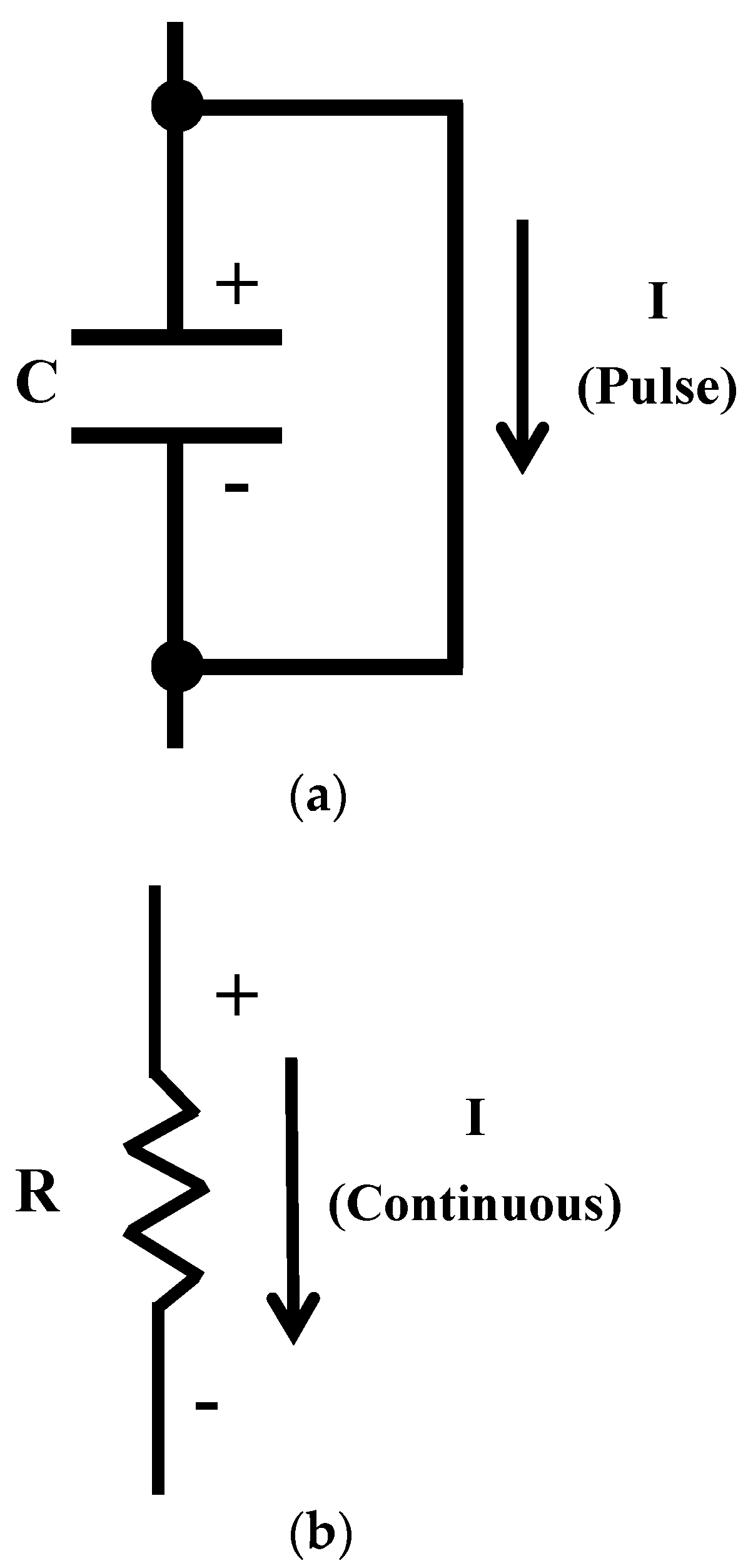
Because of the lack of conductivity, the electrets involving nonconductors functioning as capacitors, with DC electric current being not able to flow through them continuously, though a DC pulse can flow in the direction from the positive electrode to the negative electrode (Figure 1a). On the other hand, electrets that are conductors function as resistors (Figure 1b), with continuous DC flow being feasible. With the provision of both DC voltage and DC, the conductive electret serves as a power source, which is enabled by the electret and conductive behavior of a conductor. This concept is new in the field of low-power electronics. This work is directed at providing the first review of the emerging subject of conductive electrets for low-power electronics.
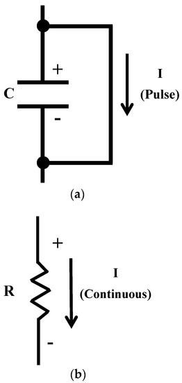
Figure 1.
Models for describing the electrical behavior of electrets. C indicates the capacitor. R indicates the resistor. I indicates the current. (a) An electret that is a nonconductor. (b) An electret that is a conductor.
Graphite differs from the abovementioned graphene [2,3] in terms of its large number of carbon layers and its wide availability in various bulk forms. Graphite is widely used for heating elements and electrochemical electrodes [63,64,65,66,67,68,69,70,71,72,73,74,75,76,77,78,79], but its electret behavior is only emerging [57,58]. Because of the electret behavior, graphite is a power-providing material in the absence of semiconductors or other two-dimensional materials, which are used in prior work on graphene [2]. Comparison of graphite with various grain sizes indicates that both the electric field in the electret and the electrical resistivity increase slightly as the grain size decreases [58].
3. Scientific Origin
The basic science is different from that of all previously reported power sources. Vibrations are not a mechanism for the energy generation of conductive electrets, although they are a mechanism in the case of nonconductive electrets. The nonconductive electrets behave as capacitors, whereas the conductive electrets behave as polarizable conductors (Figure 1). The mechanism for energy generation is described below for conductive electrets.
The permittivity is the key material property that describes the dielectric behavior. For a conductor, the permittivity originates from the interaction of a tiny fraction of the carriers with the atoms. As shown for graphite, the permittivity increases with the inverse of the grain size linearly [58]. This implies that the carrier-atom interaction occurs at the grain boundaries. The relative permittivity reaches 106 [80,81]. This is consistent with the “Giant polarizability” predicted theoretically for conductors by Jonscher (1922–2005) in 1999 [82].
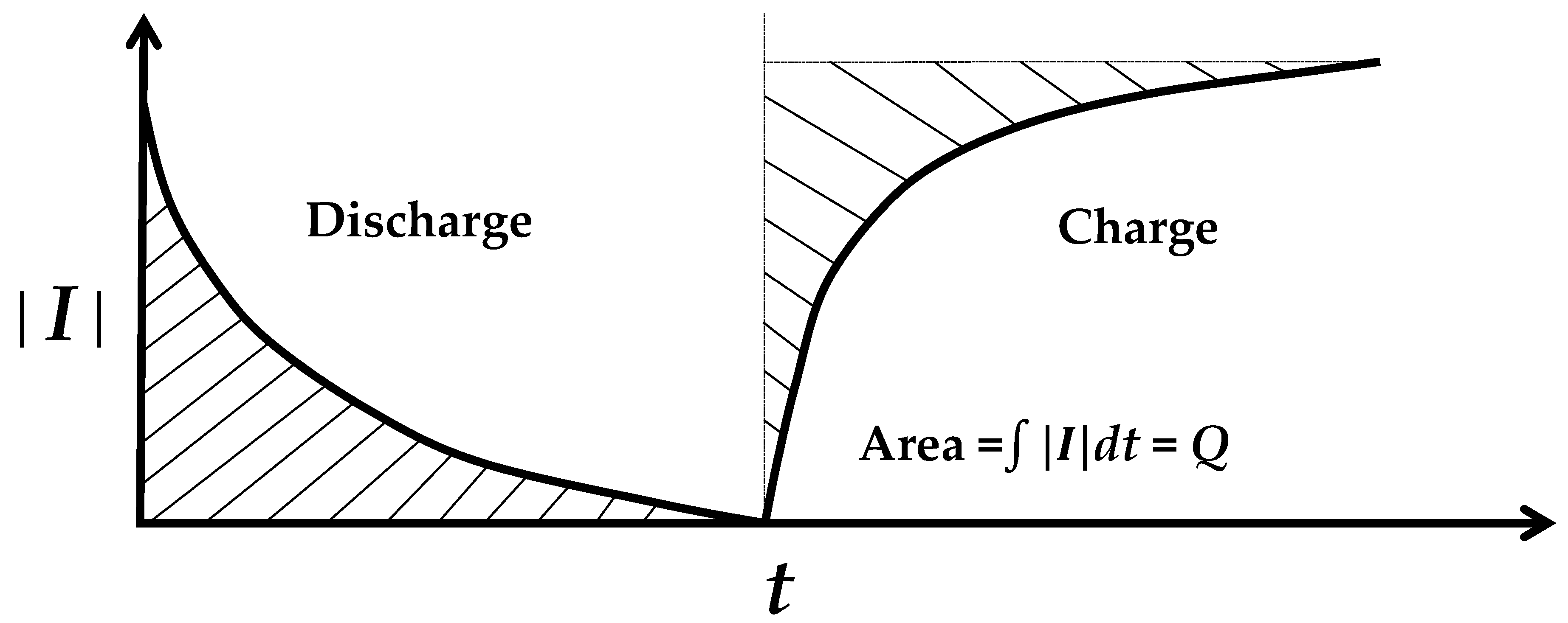
An electret discharges by short-circuiting, and charges back upon subsequent open circuiting (Figure 2). The fact that discharge occurs without the need for a prior charge is expected from the fact that the electret does not require poling. In fact, poling enhances the electret negligibly [83]. In other words, the dipole in the electret is inherent (thermodynamically stable). The greater the inter-electrode distance, the longer the discharge time [58]. The discharge/charge of an electret involves that of capacitance. This capacitance is not the well-known capacitance that relates to permittivity but is a novel type of capacitance known as the electret-based capacitance [84]. In contrast to the permittivity-based capacitance, the electret-based capacitance is defined as the magnitude of the electret charge (determined by integrating the curve of discharge current concerning the time for the entire discharge period (Figure 2) divided by the electret voltage V’. The electret-based capacitance C’ is higher than the permittivity-based capacitance C by numerous orders of magnitude [84]. For example, for Sn-4Ag lead-free solder, C’ is 620 F, whereas C is only 175 pF [84]. The time constant of the discharge/charge approximately equals RC’ (R = resistance) and the energy of the discharge/charge approximately equals ½ C’V’2, as shown for metals [84].
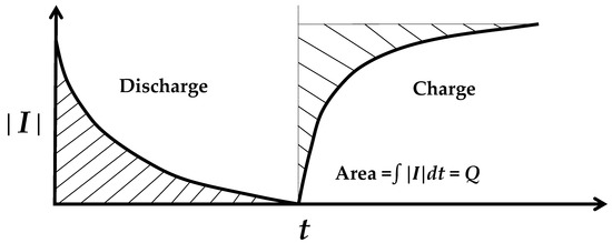
Figure 2.
The discharge–charge behavior, as illustrated by the curve of the current magnitude (│I│) as a function of time (t) during discharge (short-circuited) and the subsequent charge (open-circuited). The shaded area gives the magnitude of charge Q associated with the discharge/charge.
The fraction of carriers that interact with the atoms is much greater for the electret (DC) than the permittivity (AC polarization) [58]. For graphite (grain size 1 μm), the fraction of carriers that take part in the permittivity reaches 1.2 × 10⁻⁹, while the fraction of carriers that take part in the electret discharge reaches 6.4 × 10⁻³ [58].
A conductor functions as a resistor with low-resistance (mΩ) (usual function), a capacitor with low-capacitance (pF, permittivity-based), and a power source that provides low voltage (μV, electret-based) [85]. The extent of a function compared to the other functions depends on the dimensions. For a given value of the cross-sectional area A, increasing the length (the inter-electrode distance l) increases the voltage V’ while reducing the capacitance C (such that the capacitors are in series). For a given value of l, increasing A promotes C while reducing the resistance [85].
4. Electret Power Source Behavior
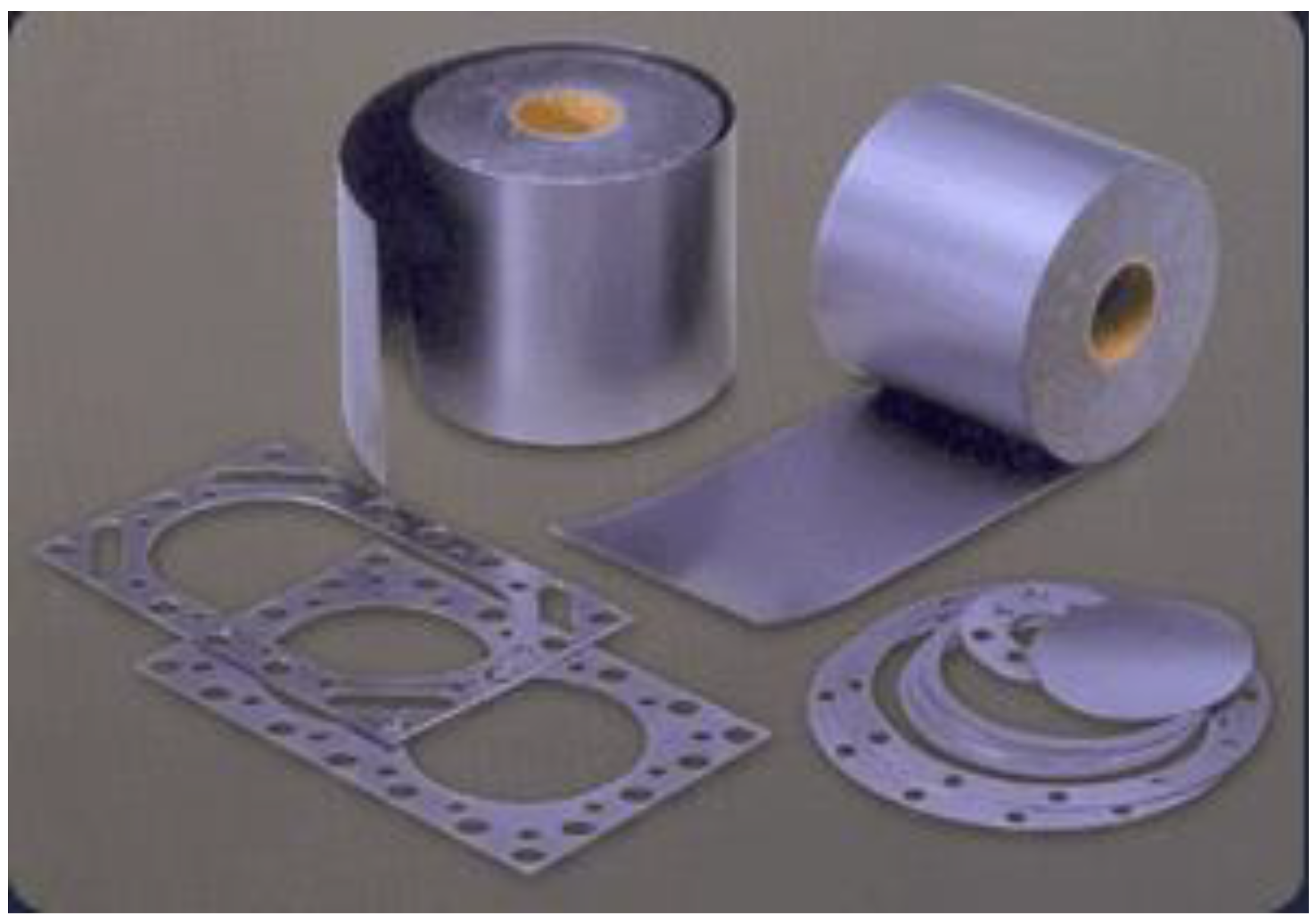
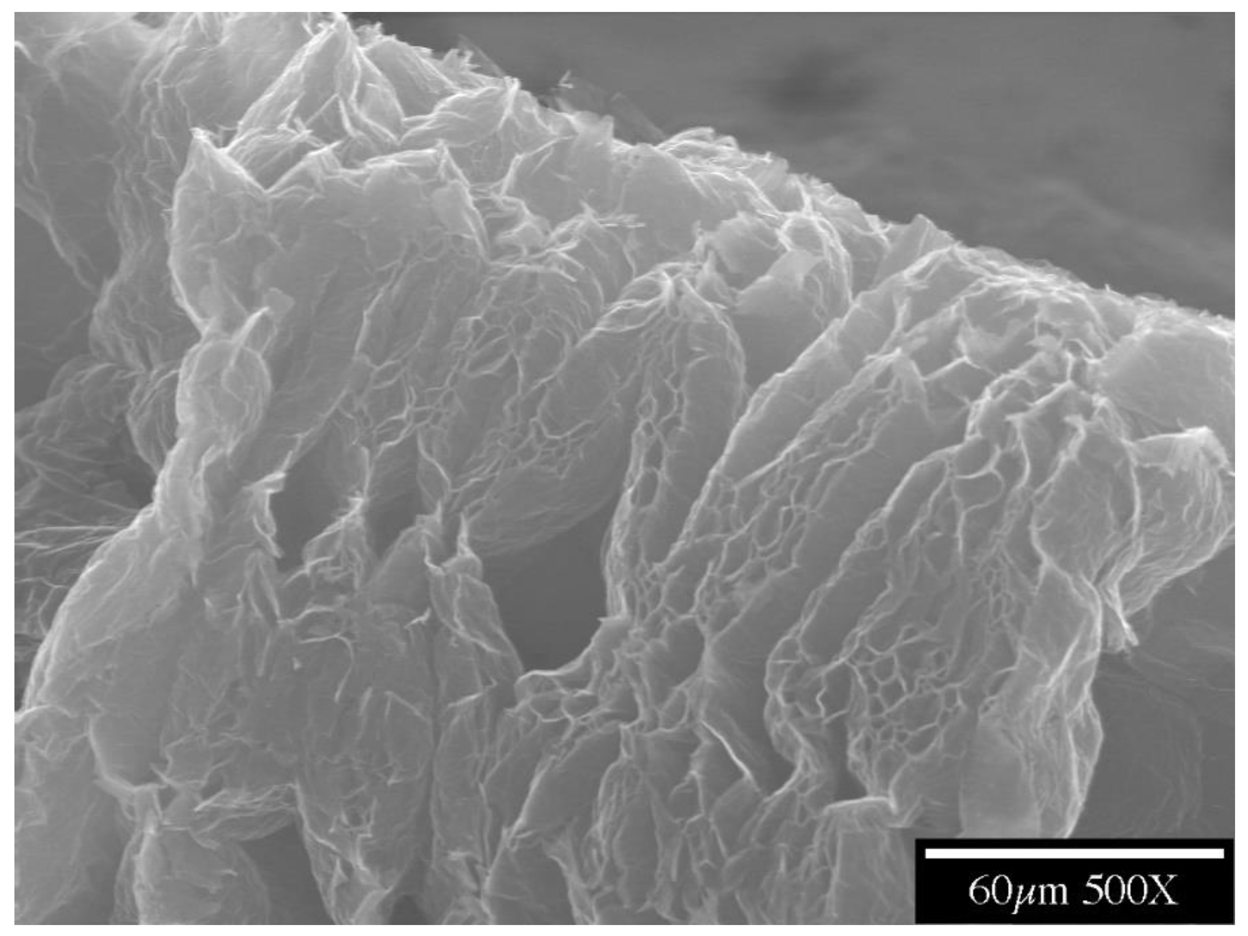
Flexible graphite is made by compacting graphite particles in the form of exfoliated graphite without a binder and is commercially available in the form of large sheets (Figure 3) [86,87,88,89,90,91,92,93,94]. Exfoliated graphite is expanded intercalated graphite, such that it has a cellular structure (Figure 4). The expansion is typically conducted by rapid heating of the intercalated graphite. Because of the cellular structure, multiple pieces of exfoliated graphite, with each piece made from a graphite flake, join by mechanical interlocking without the need for a binder.
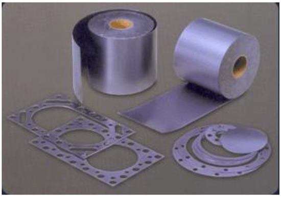
Figure 3.
Flexible graphite commercially made by compacting particles of exfoliated graphite. http://www.mvivek.com/flexible.htm (public domain) (accessed on 5 April 2023).
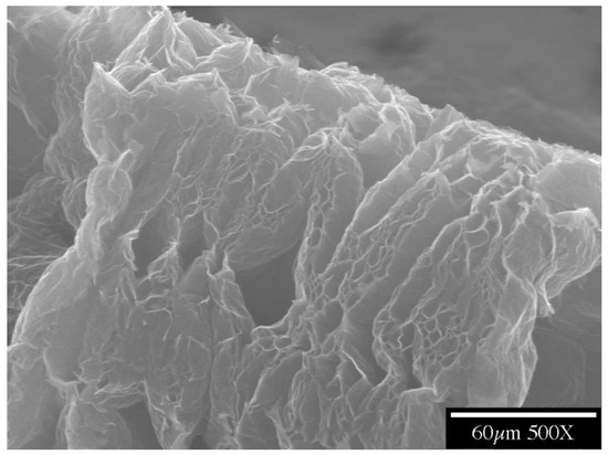
Figure 4.
A part of a piece of exfoliated graphite, as made by the expansion of intercalated graphite. The cellular structure is shown.
The greater the inter-electrode distance, the longer the discharge time [58], as mentioned in Section 3. Presumably due to the microstructure, flexible graphite in the form of large sheets (hence making large inter-electrode distances feasible) exhibits a discharge time that is so long that the electret essentially does not discharge upon short-circuiting. Thus, this material is particularly suitable for use as a power source and its electret characteristics [95] are described below.
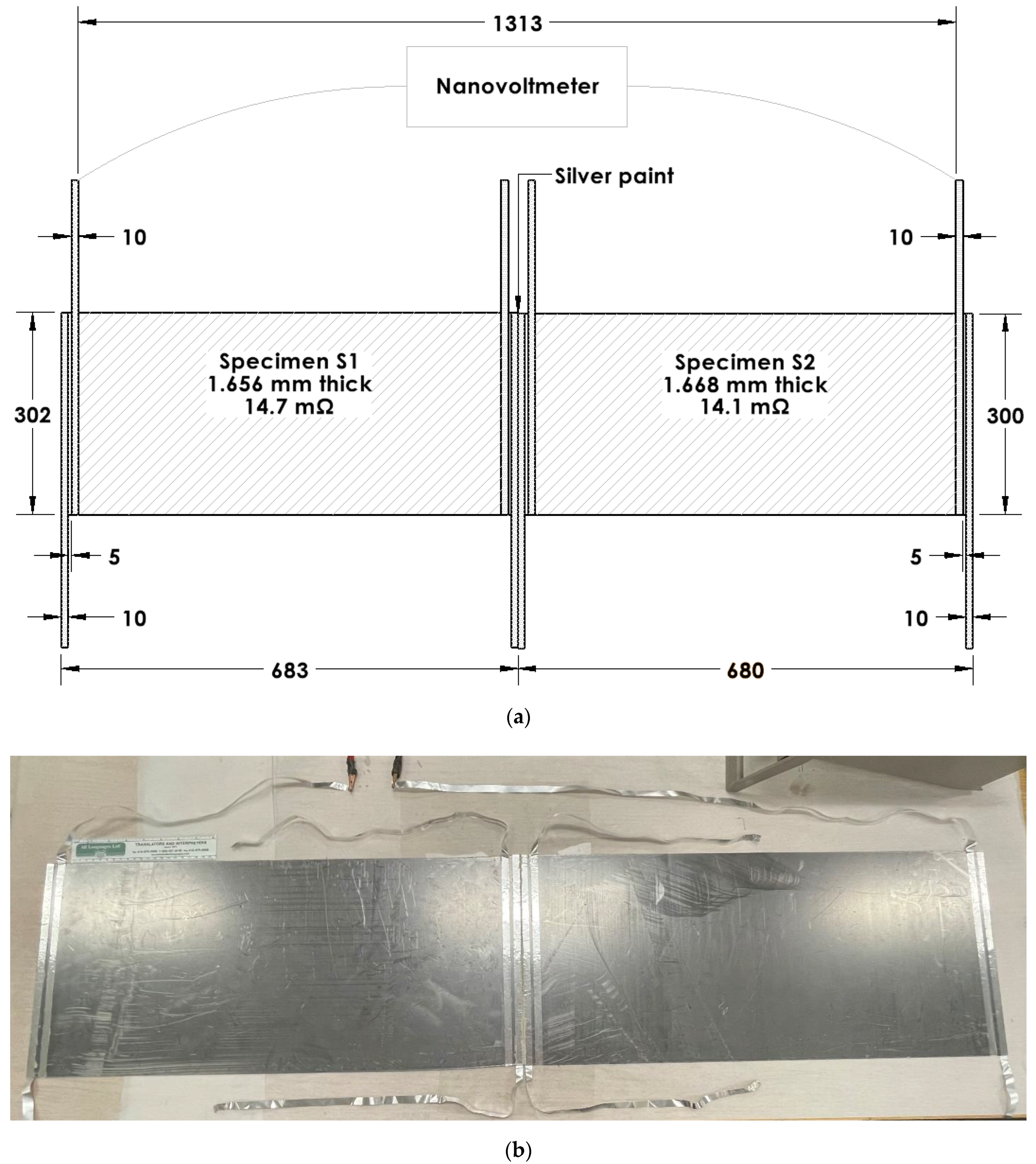
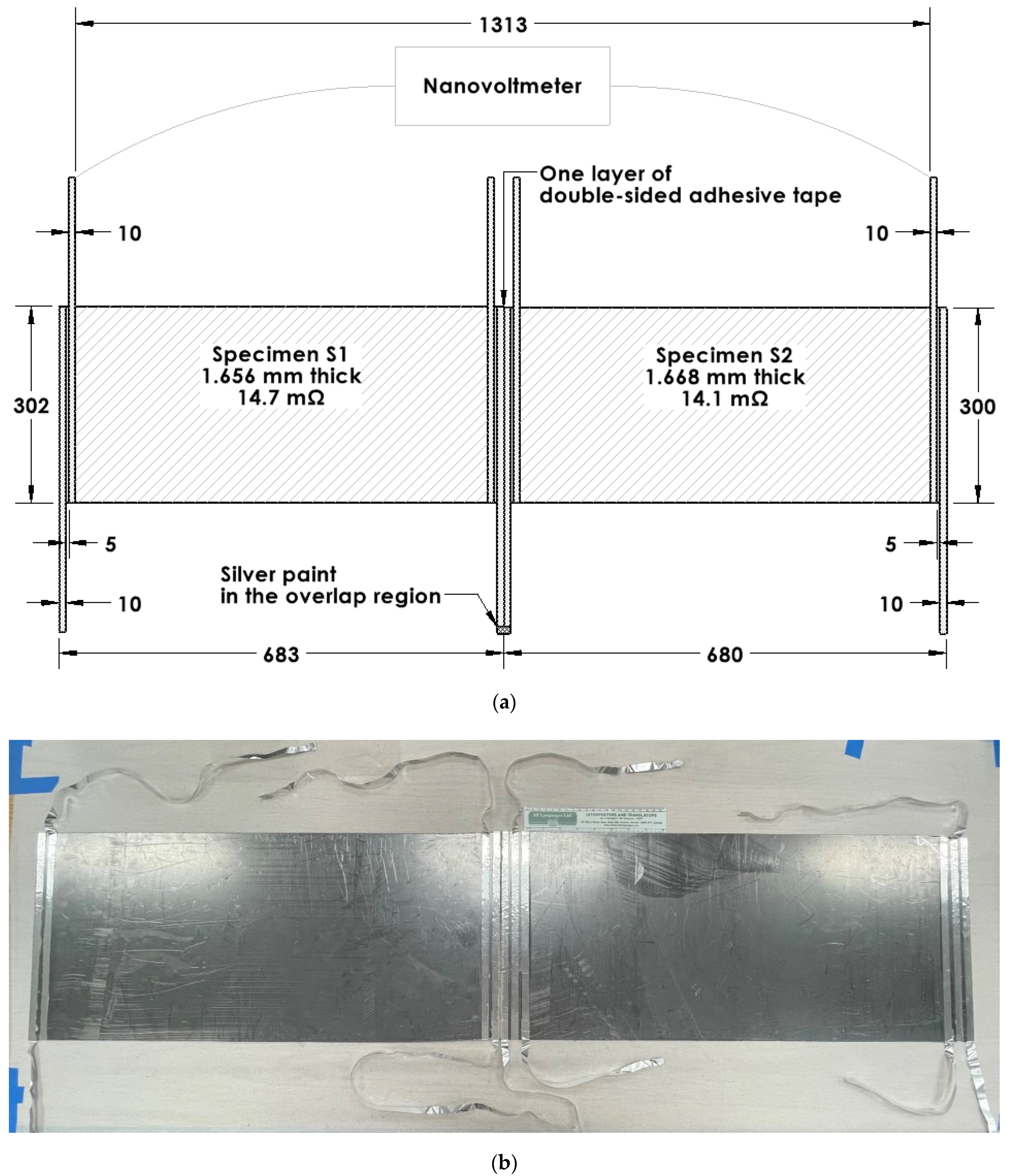
The electret voltage (Table 1) can be increased by a series connection of multiple pieces of the electret. The voltage is doubled when two essentially identical specimens are connected in series without bending the electrical connection between the two specimens, but the series voltage is roughly reduced by 50% when the electrical connection is bent [95]. This is indicated by comparing the case of an unbent connection (a silver-paint butt joint) (Figure 5) and the case of a bent connection (in the form of aluminum foil attached to the specimen by using silver paint) (Figure 6). The former gives a voltage that corresponds to the sum of the voltages of the two specimens that are disconnected from one another, but the latter gives a voltage that is less than the sum (Table 2).

Table 1.
Electrical characteristics of electret in the form of flexible graphite (specimens labeled S1 and S2). The S1 + S2 column gives the sum of the values for S1 and S2 when these two specimens are not connected electrically. The electric field is obtained by dividing the voltage by the inter-electrode distance [95].
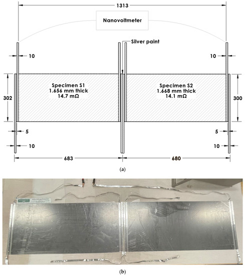
Figure 5.
Configurations for the testing of electrets in the form of flexible graphite. Two specimens (labeled S1 and S2, Table 1) are electrically connected in series. The connection involves silver paint applied to the proximate edges of the two specimens so that the connection between the two specimens is not bent. (a) Schematic illustration (dimensions in mm). (b) Photograph with the 8-inch ruler (with divisions in inches and centimeters) having main divisions in cm in its lower scale [95].

Figure 6.
Configurations for the testing of electrets in the form of flexible graphite. Two specimens (labeled S1 and S2, Table 1) are electrically connected in series, such that they are in contact along the full length of their proximate edges, except for double-sided adhesive tape between the proximate edges. The electrical connection is achieved by using two aluminum foil electrodes that have been applied to the specimens using silver paint, which is applied near the proximate edges of the two specimens. The foils protrude from the specimens and are connected by using silver paint. As a result of the protruded part of the foil, there is much bending (curling) in the connection. (a) Schematic illustration (dimensions in mm). (b) Photograph with the 8-inch ruler (with divisions in inches and centimeters) having main divisions in cm in its lower scale [95].

Table 2.
Effect of the bending of the series connection of two electrets (S1 + S2) in the form of flexible graphite. The electret voltage is compared for two cases, i.e., the case of no bending of the electrical connection and the case of bending of the connection. The two specimens (S1 + S2) positioned side by side are joined in a butt fashion at their edges. The inter-electrode distance corresponds to the distance between the proximate edges of the two voltage electrodes, with one electrode positioned close to the left end of the left specimen (S1) and the other electrode positioned close to the right end of the right specimen (S2) [95].
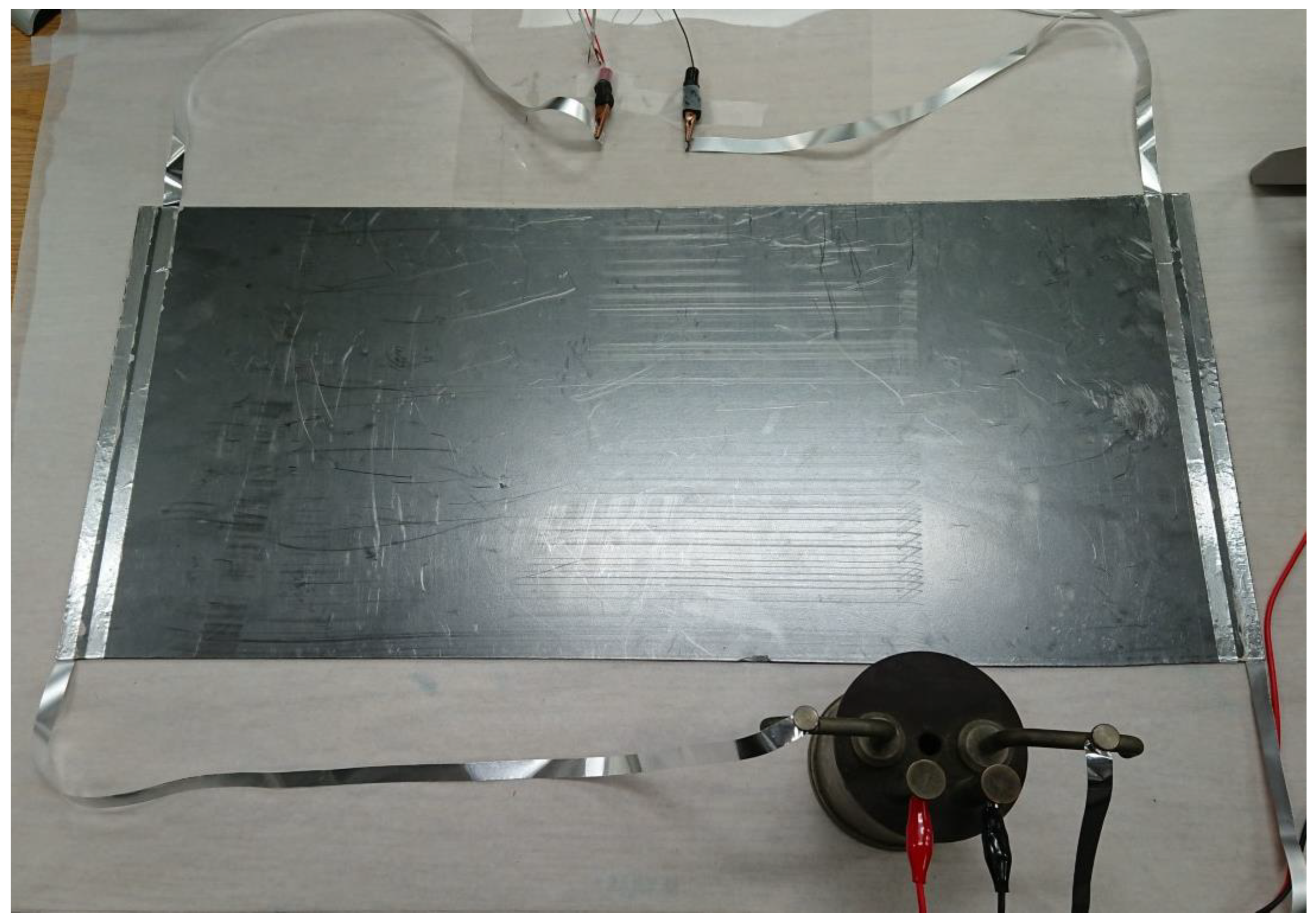
Due to the electret voltage, current passes through a series of load resistances in accordance with Ohm’s Law (Table 3, Figure 7) This supports the possibility of using the electret as a power source [95].

Table 3.
Comparison of the measured and calculated values of the voltage across a load resistor. A flexible graphite specimen (a single piece, S1, Table 1) is in series with the load resistor [95].

Figure 7.
Testing an electret in the form of flexible graphite electrically connected to a load resistor (0.1000 Ω, shown in the bottom region of the image). The specimen is the one labeled S1 (Table 1) [95].
The electret material is preferably not bent, as the bending would decrease the voltage because of the reduction in the degree of polarization continuity [95]. Polarization continuity is an emerging concept in the field of the dielectric properties of materials. This is because nonconductive materials that dominate the study of dielectric behavior are investigated in thin dimensions along the capacitance direction and the thin dimensions do not allow variations along the thickness direction for the purpose of studying the polarization continuity [96,97,98,99].
5. Conclusions
This is the first review of the emerging subject of conductive electrets (metals and carbons without poling), which provide a new avenue for low-power electronics. Electrets provide multiple electrical functions, namely, serving as power sources and providing capacitance and resistance, with the functions being tunable via the dimensions (both length and cross-sectional area) of the electret material.
Electrets provide a low-DC current voltage (μV) while allowing a low DC (μA) to pass through. Ohm’s Law is obeyed. The voltage scales with the inter-electrode distance. Series connection of multiple electret components is effective if there is no bending at the electrical connection between the components, giving a series voltage equal to the sum of the voltages of the components. In the case of bending at the electrical connection, the series voltage is below the sum. Bending within a component also diminishes the voltage because of the decrease in the degree of polarization continuity.
The science is fundamentally different from that of all previously reported power sources. The electret originates from the interaction of a tiny fraction of the carriers with the atoms. This interaction results in the charge in the electret. Dividing the electret charge by the electret voltage V’ gives the electret-based capacitance C’, which is higher than the permittivity-based capacitance (conventional) by orders of magnitude. Both V’ and permittivity depend on the microstructure, with the values increasing with decreasing grain size. The C’ governs the electret energy (1/2 C’V’2) and electret discharge time constant (RC’, where R = resistance), as shown for metals. The discharge time increases with increasing inter-electrode distance. Electret discharge occurs upon short-circuiting and charges back upon subsequent open-circuiting. The discharge/charge of the electret involves that of C’.
Low-power power sources in the form of conductive electrets constitute a new field of science. This review focuses on emerging new science. The attraction of this new technology is that poling is not required and the electret materials (whether carbons or metals) are widely available. Moreover, because of the absence of any chemical reaction and the established wide utilization of the materials in structures (e.g., steel structures), there is no environmental issue. In fact, existing structures (as opposed to new structures) may be used as power sources. The electret voltage scales with the dimensions, so large structures are preferred. Because existing large structures are abundant in almost any city, large structures such as the steel rebars in a building may be used as power sources. This would involve applying electrodes to each piece (e.g., each rebar) of the structure. By staggering the discharge start time for different pieces of electret material in the same structure, continuous energy generation by the structure may be feasible. Thus, no energy storage is needed, in contrast to this need for wind and solar forms of energy. Both the common availability of electret materials and the absence of the need for energy storage are advantageous from the cost viewpoint. However, the very low power is a disadvantage, though it is expected to increase with the dimensions and with microstructural refinement, which enhances the abundance of sites for the carrier–atom interaction that is required for the polarization. As the emerging field progresses, the power is expected to increase.
Funding
This research received no funding.
Institutional Review Board Statement
Not applicable.
Informed Consent Statement
Not applicable.
Data Availability Statement
Please refer to the original cited papers for the data availability, since this is a review paper.
Conflicts of Interest
The authors declare no conflict of interest.
References
- Lin, X.; Yang, W.; Wang, K.L.; Zhao, W. Two-dimensional spintronics for low-power electronics. Nat. Electron. 2019, 2, 274–283. [Google Scholar] [CrossRef]
- Heo, J.; Byun, K.-E.; Lee, J.; Chung, H.-J.; Jeon, S.; Park, S.; Hwang, S. Graphene and Thin-Film Semiconductor Heterojunction Transistors Integrated on Wafer Scale for Low-Power Electronics. Nano Lett. 2013, 13, 5967–5971. [Google Scholar] [CrossRef] [PubMed]
- Yan, X.; Cao, G.; Wang, J.; Man, M.; Zhao, J.; Zhou, Z.; Wang, H.; Pei, Y.; Wang, K.; Gao, C.; et al. Memristors based on multilayer graphene electrodes for implementing a low-power neuromorphic electronic synapse. J. Mater. Chem. C Mater. Opt. Electron. Devices 2020, 8, 4926–4933. [Google Scholar] [CrossRef]
- Winfield, J.; Chambers, L.D.; Stinchcombe, A.; Rossiter, J.; Ieropoulos, I. The power of glove: Soft microbial fuel cell for low-power electronics. J. Power Sources 2014, 249, 327–332. [Google Scholar] [CrossRef]
- Fanciulli, C.; Abedi, H.; Merotto, L.; Dondè, R.; De Iuliis, S.; Passaretti, F. Portable thermoelectric power generation based on catalytic combustor for low power electronic equipment. Appl. Energy 2018, 215, 300–308. [Google Scholar] [CrossRef]
- Yeh, N.; Chiu, P.; Chyi, J.; Ren, F.; Pearton, S.J. Sb-based semiconductors for low power electronics. J. Mater. Chem. C Mater. Opt. Electron. Devices 2013, 1, 4616–4627. [Google Scholar] [CrossRef]
- Das, S.; Prakash, A.; Salazar, R.; Appenzeller, J. Toward Low-Power Electronics: Tunneling Phenomena in Transition Metal Dichalcogenides. ACS Nano 2014, 8, 1681–1689. [Google Scholar] [CrossRef]
- Lee, M.H.; Wei, Y.-T.; Chu, K.-Y.; Huang, J.-J.; Chen, C.-W.; Cheng, C.-C.; Chen, M.-J.; Lee, H.-Y.; Chen, Y.-S.; Lee, L.-H.; et al. Steep Slope and Near Non-Hysteresis of FETs With Antiferroelectric-Like HfZrO for Low-Power Electronics. IEEE Electron Device Lett. 2015, 36, 294–296. [Google Scholar] [CrossRef]
- Sahu, M.; Hajra, S.; Lee, K.; Deepti, P.; Mistewicz, K.; Kim, H. Piezoelectric Nanogenerator Based on Lead-Free Flexible PVDF-Barium Titanate Composite Films for Driving Low Power Electronics. Crystals 2021, 11, 85. [Google Scholar] [CrossRef]
- He, N.; Zhang, Q.; Tao, L.; Chen, X.; Qin, Q.; Liu, X.; Lian, X.; Wan, X.; Hu, E.; Xu, J.; et al. V2C-Based Memristor for Applications of Low Power Electronic Synapse. IEEE Electron Device Lett. 2021, 42, 319–322. [Google Scholar] [CrossRef]
- Torricelli, F.; Ghittorelli, M.; Smits, E.C.P.; Roelofs, C.W.S.; Janssen, R.A.J.; Gelinck, G.H.; Kovács-Vajna, Z.M.; Cantatore, E. Ambipolar Organic Tri-Gate Transistor for Low-Power Complementary Electronics. Adv. Mater. 2015, 28, 284–290. [Google Scholar] [CrossRef] [PubMed]
- Song, Y.; Chen, X.-X.; Zhang, J.-X.; Cheng, X.-L.; Zhang, H.-X. Freestanding Micro-Supercapacitor with Interdigital Electrodes for Low-Power Electronic Systems. J. Microelectromech. Syst. 2017, 26, 1055–1062. [Google Scholar] [CrossRef]
- Yang, Y.; Du, H.; Xue, Q.; Wei, X.; Yang, Z.; Xu, C.; Lin, D.; Jie, W.; Hao, J. Three-terminal memtransistors based on two-dimensional layered gallium selenide nanosheets for potential low-power electronics applications. Nano Energy 2018, 57, 566–573. [Google Scholar] [CrossRef]
- Bergeron, H.; Sangwan, V.K.; McMorrow, J.J.; Campbell, G.P.; Balla, I.; Liu, X.; Bedzyk, M.J.; Marks, T.J.; Hersam, M.C. Chemical vapor deposition of monolayer MoS2 directly on ultrathin Al2O3 for low-power electronics. Appl. Phys. Lett. 2017, 110, 053101. [Google Scholar] [CrossRef]
- Rahi, S.B.; Tayal, S.; Upadhyay, A.K. A review on emerging negative capacitance field effect transistor for low power electronics. Microelectron. J. 2021, 116, 105242. [Google Scholar] [CrossRef]
- Rani, S.; Kumar, N.; Tandon, A.; Sharma, Y. Fabrication of Binder-Free TiO2 Nanofiber Electrodes via Electrophoretic Deposition for Low-Power Electronic Applications. IEEE Trans. Electron Devices 2020, 68, 251–256. [Google Scholar] [CrossRef]
- Moon, H.; Seong, H.; Shin, W.C.; Park, W.-T.; Kim, M.; Lee, S.; Bong, J.H.; Noh, Y.-Y.; Cho, B.J.; Yoo, S.; et al. Synthesis of ultrathin polymer insulating layers by initiated chemical vapour deposition for low-power soft electronics. Nat. Mater. 2015, 14, 628–635. [Google Scholar] [CrossRef]
- Kim, K.; Jung, M.; Kim, B.; Kim, J.; Shin, K.; Kwon, O.-S.; Jeon, S. Low-voltage, high-sensitivity and high-reliability bimodal sensor array with fully inkjet-printed flexible conducting electrode for low power consumption electronic skin. Nano Energy 2017, 41, 301–307. [Google Scholar] [CrossRef]
- Sullivan, P.; Schumann, S.; Da Campo, R.; Howells, T.; Duraud, A.; Shipman, M.; Hatton, R.A.; Jones, T.S. Ultra-high voltage multijunction organic solar cells for low-power electronic applications. Adv. Energy Mater. 2013, 3, 239–244. [Google Scholar] [CrossRef]
- Mohanta, M.K.; Fathima, I.S.; De Sarkar, A. Exceptional mechano-electronic properties in the HfN2 monolayer: A promising candidate in low-power flexible electronics, memory devices and photocatalysis. Phys. Chem. Chem. Phys. 2020, 22, 21275–21287. [Google Scholar] [CrossRef]
- Khushboo; Azad, P. A triboelectric energy harvester using human biomechanical motion for low power electronics. Bull. Mater. Sci. 2019, 42, 121. [Google Scholar] [CrossRef]
- Uzun, Y. Design and Implementation of RF Energy Harvesting System for Low-Power Electronic Devices. J. Electron. Mater. 2016, 45, 3842–3847. [Google Scholar] [CrossRef]
- Cunha, I.; Ferreira, S.H.; Martins, J.; Fortunato, E.; Gaspar, D.; Martins, R.; Pereira, L. Foldable and Recyclable Iontronic Cellulose Nanopaper for Low-Power Paper Electronics. Adv. Sustain. Syst. 2022, 6, 2200177. [Google Scholar] [CrossRef]
- Park, S.Y.; Heo, J.; Yoon, Y.J.; Kim, J.W.; Jang, H.; Walker, B.; Kim, J.Y. Synergistic combination of amorphous indium oxide with tantalum pentoxide for efficient electron transport in low-power electronics. J. Mater. Chem. C 2019, 7, 4559–4566. [Google Scholar] [CrossRef]
- Heo, J.; Park, S.Y.; Kim, J.W.; Song, S.; Yoon, Y.J.; Jeong, J.; Jang, H.; Lee, K.T.; Seo, J.H.; Walker, B.; et al. Implementation of Low-Power Electronic Devices Using Solution-Processed Tantalum Pentoxide Dielectric. Adv. Funct. Mater. 2018, 28, 1704215. [Google Scholar] [CrossRef]
- Erhard, D.P.; Lovera, D.; von Salis-Soglio, C.; Giesa, R.; Altstädt, V.; Schmidt, H.-W. Recent Advances in the Improvement of Polymer Electret Films. Adv. Polym. Sci. 2010, 228, 155–207. [Google Scholar] [CrossRef]
- Pillai, P.K.C. Polymeric electrets. Plast. Eng. 1995, 28, 1–61. [Google Scholar]
- Sessler, G.M. Electrets: Recent developments. J. Electrost. 2001, 51–52, 137–145. [Google Scholar] [CrossRef]
- Kressmann, R.; Sessler, G.M.; Guenther, P. Space-charge electrets. IEEE Trans Dielectr. Electr. Insul. 1996, 3, 607–623. [Google Scholar] [CrossRef]
- Liu, Y.-C.; Aoyagi, Y.; Chung, D.D.L. Development of epoxy-based electrets. J. Mater. Sci. 2008, 43, 1650–1663. [Google Scholar] [CrossRef]
- Huang, C.-Y.; Chung, D. Controlling and increasing the inherent voltage in cement paste. Adv. Cem. Res. 2009, 21, 31–37. [Google Scholar] [CrossRef]
- Lindner, M.; Hoislbauer, H.; Schwodiauer, R.; Bauer-Gogonea, S.; Bauer, S. Charged cellular polymers with “ferroelectretic” behavior. IEEE Trans. Dielectr. Electr. Insul. 2004, 11, 255–263. [Google Scholar] [CrossRef]
- Chen, C.-H.; Wang, Y.; Michinobu, T.; Chang, S.-W.; Chiu, Y.-C.; Ke, C.-Y.; Liou, G.-S. Donor–Acceptor Effect of Carbazole-Based Conjugated Polymer Electrets on Photoresponsive Flash Organic Field-Effect Transistor Memories. ACS Appl. Mater. Interfaces 2020, 12, 6144–6150. [Google Scholar] [CrossRef]
- Sano, C.; Ataka, M.; Hashiguchi, G.; Toshiyoshi, H. An Electret-Augmented Low-Voltage MEMS Electrostatic Out-of-Plane Actuator for Acoustic Transducer Applications. Micromachines 2020, 11, 267. [Google Scholar] [CrossRef] [PubMed]
- Sano, C.; Menon, V.; Honma, H.; Hashiguchi, G.; Toshiyoshi, H. Low-voltage-driven electrostatic microspeakers with potassium-ion-electrets. J. Physics Conf. Series 2019, 1407, 012129. [Google Scholar] [CrossRef]
- Li, Z.B.; Li, H.Y.; Fan, Y.J.; Liu, L.; Chen, Y.H.; Zhang, C.; Zhu, G. Small-sized, lightweight, and flexible triboelectric nano-generator enhanced by PTFE/PDMS nanocomposite electret. ACS Applied Mater. Interfaces 2019, 11, 20370–20377. [Google Scholar]
- Shih, C.-C.; Chiang, Y.-C.; Hsieh, H.-C.; Lin, Y.-C.; Chen, W.-C. Multilevel Photonic Transistor Memory Devices Using Conjugated/Insulated Polymer Blend Electrets. ACS Appl. Mater. Interfaces 2019, 11, 42429–42437. [Google Scholar] [CrossRef]
- Cheng, S.-W.; Han, T.; Huang, T.-Y.; Chien, Y.-H.C.; Liu, C.-L.; Tang, B.Z.; Liou, G.-S. Novel Organic Phototransistor-Based Nonvolatile Memory Integrated with UV-Sensing/Green-Emissive Aggregation Enhanced Emission (AEE)-Active Aromatic Polyamide Electret Layer. ACS Appl. Mater. Interfaces 2018, 10, 18281–18288. [Google Scholar] [CrossRef]
- Zhou, T.; Zhang, L.; Xue, F.; Tang, W.; Zhang, C.; Wang, Z.L. Multilayered electret films based triboelectric nanogenerator. Nano Res. 2016, 9, 1442–1451. [Google Scholar] [CrossRef]
- Tung, W.-Y.; Li, M.-H.; Wu, H.-C.; Liu, H.-Y.; Hsieh, Y.-T.; Chen, W.-C. High Performance Nonvolatile Transistor Memories Utilizing Functional Polyimide-Based Supramolecular Electrets. Chem. Asian J. 2016, 11, 1631–1640. [Google Scholar] [CrossRef]
- Shibata, Y.; Sugiyama, T.; Mimura, H.; Hashiguchi, G. In Situ Measurement of Charging Process in Electret-Based Comb-Drive Actuator and High-Voltage Charging. J. Microelectromech. Syst. 2014, 24, 1052–1060. [Google Scholar] [CrossRef]
- Lu, G.; Koch, N.; Neher, D. In-situ tuning threshold voltage of field-effect transistors based on blends of poly(3-hexylthiophene) with an insulator electret. Appl. Phys. Lett. 2015, 107, 063301. [Google Scholar] [CrossRef]
- Shih, C.-C.; Chiu, Y.-C.; Lee, W.-Y.; Chen, J.-Y.; Chen, W.-C. Conjugated Polymer Nanoparticles as Nano Floating Gate Electrets for High Performance Nonvolatile Organic Transistor Memory Devices. Adv. Funct. Mater. 2015, 25, 1511–1519. [Google Scholar] [CrossRef]
- Yang, Y.; Zhang, H.; Zhong, X.; Yi, F.; Yu, R.; Zhang, Y.; Wang, Z.L. Electret Film-Enhanced Triboelectric Nanogenerator Matrix for Self-Powered Instantaneous Tactile Imaging. ACS Appl. Mater. Interfaces 2014, 6, 3680–3688. [Google Scholar] [CrossRef] [PubMed]
- Thakur, R.; Das, D.; Das, A. Study of charge decay in corona-charged fibrous electrets. Fibers Polym. 2014, 15, 1436–1443. [Google Scholar] [CrossRef]
- Feng, Y.; Hagiwara, K.; Iguchi, Y.; Suzuki, Y. Trench-filled cellular parylene electret for piezoelectric transducer. Appl. Phys. Lett. 2012, 100, 262901. [Google Scholar] [CrossRef]
- Paajanen, M.; Lekkala, J.; Kirjavainen, K. ElectroMechanical Film (EMFi)—A new multipurpose electret material. Sens. Actuators A Phys. 2000, 84, 95–102. [Google Scholar] [CrossRef]
- Rychkov, A.; Kuznetsov, A.; Gulyakova, A.; Rychkov, D. Surface Potential Decay of Corona Charged Polyethylene Films: Influence of Deep Surface Traps. IEEE Trans. Dielectr. Electr. Insul. 2021, 28, 1933–1937. [Google Scholar] [CrossRef]
- Wang, J.; Rychkov, D.; Nguyen, Q.D.; Gerhard, R. Unexpected bipolar space-charge polarization across transcrystalline interfaces in polypropylene electret films. J. Appl. Phys. 2020, 128, 134103. [Google Scholar] [CrossRef]
- Lan, C.; Zou, H.; Wang, L.; Zhang, M.; Pan, S.; Ma, Y.; Qiu, Y.; Wang, Z.L.; Lin, Z. Revealing electrical-poling-induced po-larization potential in hybrid perovskite photodetectors. Adv. Mater. 2020, 32, 2005481. [Google Scholar] [CrossRef] [PubMed]
- Guliakova, A.A.; Galikhanov, M.F.; Galeeva, L.R.; Gilfanova, S.V.; Fang, P. Investigation of electret and filtering properties of polypropylene-based nonwoven fabrics and its composites with 2 vol% of silicon dioxide inclusions. IEEE Trans. Dielectr. Electr. Insul. 2020, 27, 1656–1661. [Google Scholar] [CrossRef]
- Komeijani, A.; Bagheri, H.; Shekarchi, B. Surface potential uniformity and sensitivity of large-area PTFE electret discs of different thicknesses produced by a modified corona poling rotating system for dosimetry applications. J. Adv. Dielectr. 2019, 9, 1950050. [Google Scholar] [CrossRef]
- Sohrabi, M.; Komijani, A. Modified single point-to-plane corona poling rotating system for production of electret dosimeters. IEEE Trans. Dielectr. Electr. Insul. 2018, 25, 448–456. [Google Scholar] [CrossRef]
- Horiuchi, N.; Madokoro, K.; Nozaki, K.; Nakamura, M.; Katayama, K.; Nagai, A.; Yamashita, K. Electrical conductivity of polycrystalline hydroxyapatite and its application to electret formation. Solid State Ion. 2018, 315, 19–25. [Google Scholar] [CrossRef]
- Zhang, J.W.; Gao, F.K.; Sun, H.C.; Putson, C.; Liu, R.T. Electrostrictive energy conversion property of cellular electrets after corona discharge. Int. J. Mod. Phys. B 2018, 32, 1850069. [Google Scholar] [CrossRef]
- Ko, Y.S.; Nüesch, F.A.; Opris, D.M. Charge generation by ultra-stretchable elastomeric electrets. J. Mater. Chem. C 2017, 5, 1826–1835. [Google Scholar] [CrossRef]
- Xi, X.; Chung, D. Electret, piezoelectret, dielectricity and piezoresistivity discovered in exfoliated-graphite-based flexible graphite, with applications in mechanical sensing and electric powering. Carbon 2019, 150, 531–548. [Google Scholar] [CrossRef]
- Xi, X.; Chung, D.D.L. Dielectric behavior of graphite, with assimilation of the AC permittivity, DC polarization and DC electret. Carbon 2021, 181, 246–259. [Google Scholar] [CrossRef]
- Xi, X.; Chung, D. Electret behavior of unpoled carbon fiber with and without nickel coating. Carbon 2019, 159, 122–132. [Google Scholar] [CrossRef]
- Xi, X.; Chung, D. Electret behavior of carbon fiber structural composites with carbon and polymer matrices, and its application in self-sensing and self-powering. Carbon 2020, 160, 361–389. [Google Scholar] [CrossRef]
- Xi, X.; Chung, D.D.L. Electret, piezoelectret and piezoresistivity discovered in steels, with application to structural self-sensing and structural self-powering. Smart Mater. Struct. 2019, 28, 075028. [Google Scholar] [CrossRef]
- Yang, W.; Chung, D.D.L. Electret behavior discovered in solder, specifically tin–silver. J. Mater. Sci. Mater. Electron. 2021, 32, 19145–19156. [Google Scholar] [CrossRef]
- David, I.G.; Popa, D.-E.; Buleandra, M. Pencil Graphite Electrodes: A Versatile Tool in Electroanalysis. J. Anal. Methods Chem. 2017, 2017, 1905968. [Google Scholar] [CrossRef]
- Billaud, J.; Bouville, F.; Magrini, T.; Villevieille, C.; Studart, A.R. Magnetically aligned graphite electrodes for high-rate performance Li-ion batteries. Nat. Energy 2016, 1, 16097. [Google Scholar] [CrossRef]
- Bhauriyal, P.; Mahata, A.; Pathak, B. The staging mechanism of AlCl4 intercalation in a graphite electrode for an aluminiumion battery. Phys. Chem. Chem. Phys. 2017, 19, 7980–7989. [Google Scholar] [CrossRef] [PubMed]
- Fan, L.; Liu, Q.; Chen, S.; Lin, K.; Xu, Z.; Lu, B. Potassium-Based Dual Ion Battery with Dual-Graphite Electrode. Small 2017, 13, 1701011. [Google Scholar] [CrossRef] [PubMed]
- Fan, H.; Qi, L.; Wang, H. Hexafluorophosphate anion intercalation into graphite electrode from methyl propionate. Solid State Ion. 2017, 300, 169–174. [Google Scholar] [CrossRef]
- Cai, W.; Yan, C.; Yao, Y.; Xu, L.; Chen, X.; Huang, J.; Zhang, Q. The Boundary of Lithium Plating in Graphite Electrode for Safe Lithium-Ion Batteries. Angew. Chem. Int. Ed. 2021, 60, 13007–13012. [Google Scholar] [CrossRef] [PubMed]
- Finegan, D.P.; Quinn, A.; Wragg, D.S.; Colclasure, A.M.; Lu, X.; Tan, C.; Heenan, T.M.M.; Jervis, R.; Brett, D.J.L.; Das, S.; et al. Spatial dynamics of lithiation and lithium plating during high-rate operation of graphite electrodes. Energy Environ. Sci. 2020, 13, 2570–2584. [Google Scholar] [CrossRef]
- Patil, M.M.; Shetti, N.P.; Malode, S.J.; Nayak, D.S.; Chakklabbi, T.R. Electroanalysis of paracetamol at nanoclay modified graphite electrode. Mater. Today Proc. 2019, 18, 986–993. [Google Scholar] [CrossRef]
- Zhu, S.; Zhang, L.; Huang, Y.; Li, J.; Fan, H.; Wang, H. Ethylmethyl carbonate’s role in hexafluor-ophosphate storage in graphite electrodes. ACS Appl. Energy Mater. 2019, 2, 8031–8038. [Google Scholar] [CrossRef]
- Goktas, M.; Bolli, C.; Buchheim, J.; Berg, E.J.; Novák, P.; Bonilla, F.; Rojo, T.; Komaba, S.; Kubota, K.; Adelhelm, P. Stable and Unstable Diglyme-Based Electrolytes for Batteries with Sodium or Graphite as Electrode. ACS Appl. Mater. Interfaces 2019, 11, 32844–32855. [Google Scholar] [CrossRef] [PubMed]
- Hogrefe, C.; Hein, S.; Waldmann, T.; Danner, T.; Richter, K.; Latz, A.; Wohlfahrt-Mehrens, M. Mechanistic Details of the Spontaneous Intercalation of Li Metal into Graphite Electrodes. J. Electrochem. Soc. 2020, 167, 140546. [Google Scholar] [CrossRef]
- Zhang, L.; Li, J.; Huang, Y.; Zhu, D.; Wang, H. Synergetic Effect of ethyl methyl carbonate and trime-thyl phosphate on BF4- intercalation into a graphite electrode. Langmuir 2019, 35, 3972–3979. [Google Scholar] [CrossRef]
- Sharma, S.; Jain, R.; Raja, A.N. Review-pencil graphite electrode: An emerging sensing material. J. Electrochem. Soc. 2020, 167, 037501. [Google Scholar]
- Huang, Y.; Fan, H.; Kamezaki, H.; Kang, B.; Yoshio, M.; Wang, H. Facilitating Tetrafluoroborate Intercalation into Graphite Electrodes from Ethylmethyl Carbonate-Based Solutions. Chemelectrochem 2019, 6, 2931–2936. [Google Scholar] [CrossRef]
- Morasch, R.; Landesfeind, J.; Suthar, B.; Gasteiger, H. Detection of Binder Gradients Using Impedance Spectroscopy and Their Influence on the Tortuosity of Li-Ion Battery Graphite Electrodes. J. Electrochem. Soc. 2018, 165, A3459–A3467. [Google Scholar] [CrossRef]
- Amin, R.; Delattre, B.; Tomsia, A.P.; Chiang, Y.-M. Electrochemical Characterization of High Energy Density Graphite Electrodes Made by Freeze-Casting. ACS Appl. Energy Mater. 2018, 1, 4976–4981. [Google Scholar] [CrossRef]
- Liu, L.; Solin, N.; Inganäs, O. Scalable lignin/graphite electrodes formed by mechanochemistry. RSC Adv. 2019, 9, 39758–39767. [Google Scholar] [CrossRef]
- Chung, D.; Xi, X. A review of the colossal permittivity of electronic conductors, specifically metals and carbons. Mater. Res. Bull. 2021, 148, 111654. [Google Scholar] [CrossRef]
- Chung, D.; Xi, X. Factors that govern the electric permittivity of carbon materials in the graphite allotrope family. Carbon 2021, 184, 245–252. [Google Scholar] [CrossRef]
- Jonscher, A.K. Dielectric relaxation in solids. J. Phys. D Appl. Phys. 1999, 32, R57–R70. [Google Scholar] [CrossRef]
- Chung, D.; Xi, X. Electric poling of carbon fiber with and without nickel coating. Carbon 2020, 162, 25–35. [Google Scholar] [CrossRef]
- Chung, D.D.L.; Xi, X. New concept of electret-based capacitance, as shown for solder and other conductors. J. Mater. Sci. Mater. Electron. 2022, 33, 27022–27039. [Google Scholar] [CrossRef]
- Chung, D.D.L.; Xi, X. Introducing solder-based electronics, with solder functioning as resistor, capacitor, and power source. J. Mater. Sci. Mater. Electron. 2023, 34, 131. [Google Scholar] [CrossRef]
- Chung, D.D.L. A review of exfoliated graphite. J. Mater. Sci. 2015, 51, 554–568. [Google Scholar] [CrossRef]
- Xin, G.; Wang, Y.; Liu, X.; Zhang, J.; Wang, Y.; Huang, J.; Zang, J. Preparation of self-supporting graphene on flexible graphite sheet and electrodeposition of polyaniline for supercapacitor. Electrochim. Acta 2015, 167, 254–261. [Google Scholar] [CrossRef]
- Sykam, N.; Rao, G.M. Lightweight flexible graphite sheet for high-performance electromagnetic interference shielding. Mater. Lett. 2018, 233, 59–62. [Google Scholar] [CrossRef]
- Liu, Y.; Zeng, J.; Han, D.; Wu, K.; Yu, B.; Chai, S.; Chen, F.; Fu, Q. Graphene enhanced flexible expanded graphite film with high electric, thermal conductivities and EMI shielding at low content. Carbon 2018, 133, 435–445. [Google Scholar] [CrossRef]
- Muniraj VK, A.; Dwivedi, P.K.; Tamhane, P.S.; Szunerits, S.; Boukherroub, R.; Shelke, M.V. High-energy flexible supercapacitor-synergistic effects of polyhydroquinone and RuO2·×H2O with microsized, few-layered, self-supportive exfoliated-graphite sheets. ACS Appl. Mater. Interfaces 2019, 11, 18349–18360. [Google Scholar] [CrossRef] [PubMed]
- Liu, Y.; Zhang, K.; Mo, Y.; Zhu, L.; Yu, B.; Chen, F.; Fu, Q. Hydrated aramid nanofiber network enhanced flexible expanded graphite films towards high EMI shielding and thermal properties. Compos. Sci. Technol. 2018, 168, 28–37. [Google Scholar] [CrossRef]
- Goren, A.Y.; Recepoğlu, Y.K.; Edebali̇, O.; Sahin, C.; Genisoglu, M.; Okten, H.E. Electrochemical Degradation of Methylene Blue by a Flexible Graphite Electrode: Techno-Economic Evaluation. ACS Omega 2022, 7, 32640–32652. [Google Scholar] [CrossRef] [PubMed]
- Li, H.-Y.; Yu, Y.; Liu, L.; Liu, L.; Wu, Y. One-step electrochemically expanded graphite foil for flexible all-solid supercapacitor with high rate performance. Electrochim. Acta 2017, 228, 553–561. [Google Scholar] [CrossRef]
- Liu, Y.; Qu, B.; Wu, X.; Tian, Y.; Wu, K.; Yu, B.; Du, R.; Fu, Q.; Chen, F. Utilizing ammonium persulfate assisted expansion to fabricate flexible expanded graphite films with excellent thermal conductivity by introducing wrinkles. Carbon 2019, 153, 565–574. [Google Scholar] [CrossRef]
- Chung, D.; Duong, D.Q. Observation of electric polarization continuity in graphite. Mater. Chem. Phys. 2023, 297, 127357. [Google Scholar] [CrossRef]
- Ukpaka, C.P. Mathematical model to predict the characteristics of polarization in dielectric materials: The concept of piezoelectrcity and electrostriction. Chem. Int. 2019, 5, 232–240. [Google Scholar]
- Zhang, G.; Brannum, D.; Dong, D.; Tang, L.; Allahyarov, E.; Tang, S.; Kodweis, K.; Lee, J.-K.; Zhu, L. Interfacial Polarization-Induced Loss Mechanisms in Polypropylene/BaTiO3 Nanocomposite Dielectrics. Chem. Mater. 2016, 28, 4646–4660. [Google Scholar] [CrossRef]
- Quan, B.; Liang, X.; Ji, G.; Cheng, Y.; Liu, W.; Ma, J.; Zhang, Y.; Li, D.; Xu, G. Dielectric polarization in electromagnetic wave absorption: Review and perspective. J. Alloys Compd. 2017, 728, 1065–1075. [Google Scholar] [CrossRef]
- Kim, M.P.; Um, D.-S.; Shin, Y.-E.; Ko, H. High-Performance Triboelectric Devices via Dielectric Polarization: A Review. Nanoscale Res. Lett. 2021, 16, 35. [Google Scholar] [CrossRef]
Disclaimer/Publisher’s Note: The statements, opinions and data contained in all publications are solely those of the individual author(s) and contributor(s) and not of MDPI and/or the editor(s). MDPI and/or the editor(s) disclaim responsibility for any injury to people or property resulting from any ideas, methods, instructions or products referred to in the content. |
© 2023 by the author. Licensee MDPI, Basel, Switzerland. This article is an open access article distributed under the terms and conditions of the Creative Commons Attribution (CC BY) license (https://creativecommons.org/licenses/by/4.0/).

