Article

Twisted Silica Microstructured Optical Fiber with Equiangular Spiral Six-Ray Geometry

by
Anton V. Bourdine
1,2,3,4,*,
Alexey Yu. Barashkin
1,
Vladimir A. Burdin
1,
Michael V. Dashkov
1,
Vladimir V. Demidov
2,
Konstantin V. Dukelskii
2,4,5,
Alexander S. Evtushenko
1,
Yaseera Ismail
6,
Alexander V. Khokhlov
2,
Artem A. Kuznetsov
7,
Alexandra S. Matrosova
2,5,
Oleg G. Morozov
7,
Grigori A. Pchelkin
2,8,
Francesco Petruccione
6,9,
Airat Zh. Sakhabutdinov
7,
Ghanshyam Singh
10,
Egishe V. Ter-Nersesyants
2,
Manish Tiwari
10,
Elena S. Zaitseva
1,
Vijay Janyani
10 and
Juan Yin
11
add Show full author list remove Hide full author list
1
Department of Communication Lines, Povolzhskiy State University of Telecommunications and Informatics, 23, Lev Tolstoy Street, Samara 443010, Russia
2
JSC “Scientific Production Association State Optical Institute Named after Vavilov S.I.”, 36/1, Babushkin Street, St. Petersburg 192171, Russia
3
“OptoFiber Lab” LLC., Skolkovo Innovation Center, Nobel Street, Moscow 143026, Russia
4
Department of Photonics and Communication Links, Saint Petersburg State University of Telecommunications Named after M.A. Bonch-Bruevich, 22, Bolshevikov Avenue, St. Petersburg 193232, Russia
5
Faculty of Photonics and Optical Information, School of Photonics, ITMO University, bldg. A, 49, Kronverksky Alley, St. Petersburg 197101, Russia
6
Quantum Research Group, School of Chemistry and Physics, University of KwaZulu-Natal, Durban 4001, South Africa
7
Department of Radiophotonics and Microwave Technologies, Kazan National Research Technical University Named after A.N. Tupolev-KAI, 10, Karl Marx Street, Kazan, Republic of Tatarstan 420111, Russia
8
Institute of Physics, Nanotechnology and Telecommunications, Peter the Great St. Petersburg Polytechnic University, bldg. II, 29, Politekhnicheskaya Str., St. Petersburg 194064, Russia
9
National Institute for Theoretical Physics, KwaZulu-Natal, Durban 4001, South Africa
10
Department of Electronics and Communication Engineering, School of Electrical and Electronics & Communication Engineering, Manipal University Jaipur, Jaipur-Ajmer Expressway, Rajastan 303007, India
11
Division of Quantum Physics and Quantum Information, University of Science and Technology of China, No.99 Xiupu Road, Pudong District, Shanghai 200093, China
*
Author to whom correspondence should be addressed.
Fibers 2021, 9(5), 27; https://doi.org/10.3390/fib9050027
Submission received: 8 February 2021 / Revised: 23 March 2021 / Accepted: 26 April 2021 / Published: 2 May 2021
(This article belongs to the Special Issue Optical Fibers as a Key Element of Distributed Sensor Systems)

Abstract

:
This work presents fabricated silica microstructured optical fiber with special equiangular spiral six-ray geometry, an outer diameter of 125 µm (that corresponds to conventional commercially available telecommunication optical fibers of ratified ITU-T recommendations), and induced chirality with twisting of 200 revolutions per minute (or e.g., under a drawing speed of 3 m per minute, 66 revolutions per 1 m). We discuss the fabrication of twisted microstructured optical fibers. Some results of tests, performed with pilot samples of designed and manufactured stellar chiral silica microstructured optical fiber, including basic transmission parameters, as well as measurements of near-field laser beam profile and spectral and pulse responses, are represented.

1. Introduction

Twisted optical fibers have been known since the early 1980s: here the concept of fiber spinning was originally introduced for the first time in the work of [1], and it is based on rotation of preform during the fiber drawing [1] or direct spinning of the drawn fiber instead of preform [2]. For single-mode optical fibers, the described technique is declared as the method for polarization mode dispersion (PMD) reduction [1,2,3,4], while for multimode optical fibers, induced chirality (including twisting) is considered as one of the methods for differential mode delay (DMD), decreasing with total bandwidth improvement [5,6]. Twisted large core optical fibers are associated with great potentiality for applications in high-power fiber lasers with either active optical fibers with a higher-order mode-suppression property [7] or optical fibers with improved mode coupling for cladding pumped devices [8].
Nowadays, twisted microstructured optical fibers (MOFs) are considered as novel fiber optic elements with great potentiality for various applications in both fiber optic sensors/sensor networks and telecommunications [9]. The same technique for chirality induction during MOF drawing was introduced for the first time in 2004 in the work of [10], and provided significant PMD reduction. At the present time, there are known published works (both theory and containing practice implementation), declaring twisted MOFs as polarization-maintaining fiber optic devices with generation optical activity [11,12,13,14,15], fiber optic probes for strain and twist sensing [16] as well as for current and magnetic field sensing [17], spectral and mode filters [18], optical tweezers, and optical angular orbital momentum (OAM)-based telecommunications [19,20,21,22,23,24,25,26,27].
This work presents fabricated twisted silica MOF with equiangular spiral six-ray (ESSR) geometry, an outer diameter of 125 µm (that corresponds to conventional commercially available telecommunication optical fibers of ratified ITU-T recommendations), and induced chirality with twisting of 200 revolutions per minute (or e.g., under a drawing speed of 3 m per minute, 66 revolutions per 1 m). The first part of the paper is focused on the manufacturing technique of twisted MOFs following application for fabrication of pilot samples of the originally designed ESSR-MOF, scaled to 125 µm outer diameter, while the second part is concerned with theoretical and experimental research of their characteristics. We report some results of tests, performed for pilot samples of ESSR-MOF, including basic transmission parameters as well as measurements of near-field laser beam profile and both spectral and pulse responses. According to the performed series of tests, which demonstrated low attenuation and the ability to impact differential mode delay, fabricated pilot samples of ESSR-MOF with induced chirality show good potentiality for utilization in the various above-mentioned applications of twisted MOFs, which undoubtedly requires additional future research.

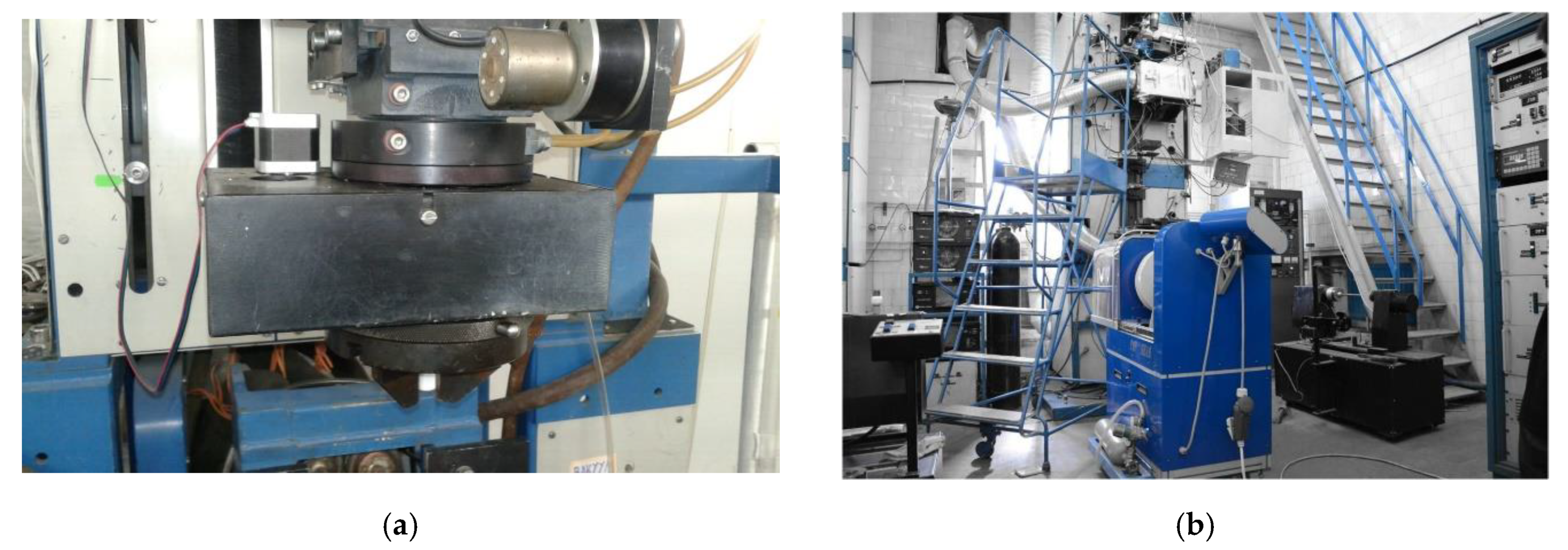
2. Fabrication of Twisted Silica Microstructured Optical Fibers

Manufacturing of chiral (twisted) silica MOF includes the following three steps. The first two are concerned with MOF stack (preform) and cane (prefiber) fabrication. These steps do not differ from any other silica MOF stack and cane forming. Here, preliminarily, by using a drawing tower, microelements (micro-rods and capillaries (micro-tubes), made of high-purity fused synthetic silica glass with a content of hydroxyl groups less than 1.0 ppm, are drawn. These microelements further will form the internal structure of MOF cane. In this work we utilized microelements with an outer diameter 1.53 mm. Then capillaries and micro-rods were mechanically cut into segments of 30 cm long each. Each side end of the capillaries was melted in the flame of stationary oxyhydrogen torch under blowing by dried oxygen (hydroxyl group content less 0.2 ppm). After that, capillaries with melted ends and microrods were short-term (2–3 min) etched in concentrated hydrofluoric acid with the following chemical cleaning in polar and nonpolar solvents, washed by distilled water, and further dried in a muffle furnace. The capillaries and micro-rods were then manually placed inside a high-purity fused synthetic silica glass substrate tube with content of hydroxyl groups less than 1.0 ppm and an inner diameter of 17 mm, according to the desired cross-section structure of designed MOF. The final operation of the described step was melting of the substrate tube end by using thermomechanical machine equipment of MCVD station to prevent structural rupture of the prepared MOF stack.
During the second step, MOF cane was drawn. Here the MOF stack was installed in the feed unit of the drawing tower. Its melted end was driven into the high-temperature furnace and re-drawn under the control of ratio between the cane drawing speed and speed of stack feeding to the furnace. We manufactured the MOF cane under the following process parameters: Stack feeding speed is 10 mm per minute; cane drawing speed is 0.5 m per minute; and drawing temperature is 1950 °C. The main aim of the described stage was preparation of the desired cross-section structure of MOF by taking into account that air gaps between capillaries and micro-rods in the stack should be completely melted in the cane. For this purpose, we additionally utilized vacuuming during the drawing of the cane from the stack under a pressure of 0.5 atm. Therefore, at the end of step 2, we fabricated MOF cane with an outer diameter of 3 mm and length 1 m.
After the third step, we designed the MOF with the desired outer diameter, covered by acrylate coating. During this stage, the fabricated cane was installed into the feed unit of the drawing tower, then it was driven into the high-temperature furnace and re-drawn to optical fiber analogously to the above-described previous stage. We utilized the same approach as the technique, proposed in [1], which is concerned with optical fiber cane rotation during the drawing process.
Therefore, some modifications of the drawing tower were performed: Here we integrated the stepper motor to the feed unit (Figure 1a), which added a new rotation function to the drawing system. The maximal rotation speed of the stepper motor is 200 rpm, which provides chirality of approximately 100 revolutions per meter under the drawing speed 2 m per minute. An excess pressure was fed into the MOF cane to manage and control capillary dimensions (air hole relative size defines the number of propagating transversal modes as well as their transmission parameters (propagation constant, delay, dispersion, attenuation etc.)). During its propagation, feed gas heats up in the head space of the high-temperature furnace and expands, which increases the size of the air holes. Therefore, MOF air hole size is also managed by temperature in the furnace. The implementation of the described technique is quite simple: Usually, for pressure supply, here a plastic hose with appropriate size is put on the end of cane. However, in the case of added rotation of the cane (especially, under the high rotation speed), the hose cannot be used due to its twisting and following destruction. For this described reason, we developed and fabricated a special fluoroplastic rotational adapter (Figure 1b–d), which successfully solves three problems at once: (1) it provides cane rotation during the MOF drawing under the desired speed; (2) connects an excess pressure hose to the top end of the cane and fixes it without twisting; (3) eliminates drop of pressure in the space between the hose and the top end of the cane due to sealed internal space of the rotational adapter.
During the first series of test drawings, we did not feed excess pressure to the cane capillaries, but gradually increased the temperature from 1880 °C to 1890 °C with steps of 10 °C. As it was expected, the desired microstructure (e.g., longitudinal voids) of fabricated samples of twisted optical fibers was collapsed due to surface tension forces. Under the next stage, we fed high-purity argon to the cane capillaries with a pressure of 20 mbar using the rotational adapter described above. As a result, we have drawn a sample of chiral optical fiber with the microstructure (longitudinal voids “swelled” due to hot argon feeding over cane capillaries), however, here the air hole diameter to the pitch ratio was unacceptably low, about 0.5 and less. Therefore, during the next step, drawing temperature was increased firstly up to 1890 °C, which led to improvement of air hole diameter to the pitch ratio up to 0.8, while the following set of temperature to 1900 °C provided growing of the above-mentioned ratio up to 0.9. Finally, we successfully fabricated twisted MOF with the desired air hole diameter to the pitch ratio 0.95 under some increased hot argon pressure up to 25 mbar and the same drawing temperature 1900 °C.
Therefore, the presented modifications of the drawing tower (Figure 2) provide fabrication of MOFs with induced chirality from 10 revolutions per meter (rotation speed is 20 rpm with MOF drawing speed 2 m per minute) up to 66 revolutions per meter (rotation speed is 200 rpm with MOF drawing speed 3 m per minute) under a drawing temperature of 1900 °C and excess pressure of 25 mbar. Fabricated MOFs are placed on typical plastic spools for conventional telecommunication silica optical fibers with a diameter of 15.8 cm.

3. Twisted Silica Microstructured Optical Fibers with Equiangular Spiral Six-Ray Geometry

The design of equiangular spiral six-ray geometry ESSR-MOF (Figure 3a) was inspired by a six-arm alloy wheel. It is supposed that spiral geometry of MOF combined with induced chirality would improve modal stability. We prepared fiber stack, then redrew it in the cane with an outer diameter of 2.92 mm (Figure 3b). After that, two ESSR-MOF samples with lengths of about 20 m each were drawn with induced chirality of 10 and 66 revolutions per meter and were fabricated (Figure 3c). Images of twisted ESSR-MOF sample fragments are shown in Figure 4a,b. The geometry of fabricated ESSR-MOF is scaled to an outer diameter 125 µm, which is a typical cladding diameter for conventional commercially available telecommunication optical fibers, to simplify following connection to measurement/test equipment.
The results of near-field measurements of the laser beam profile after propagation over the fabricated 20-m length ESSR-MOF sample with a chirality of 66 revolutions per meter, placed on a conventional optical fiber plastic spool with a diameter of 15.8 cm, under various receiving conditions, are presented in Figure 5. We used single-mode semiconductor laser source, operating at wavelength λ = 1550 nm. Optical emission, generated by the laser, was launched to ESSR-MOF via free space by using the focusing system, containing plane-parallel laser beam former and focusing objective. Optical fiber end-face precision placement in relation to the focused laser beam was performed by positioning the stage with micrometer sliders, providing shifting steps of 1 µm in a plane, perpendicular to the laser beam cross section plane. Here, Figure 5b–d correspond to the ESSR-MOF segment with the smallest size air holes (air hole diameter to the pitch ratio is 0.90—Figure 5a), while Figure 5f–h correspond to the maximal size. We shot pictures under the following receiving conditions (air hole diameter to the pitch ratio is 0.90—Figure 5e): Figure 5b,f—ESSR-MOF end face is placed in the focus of the camera lens; Figure 5c—ESSR-MOF end face is placed in the focus of the camera lens; receiving is performed via phase plate; Figure 5d,g—ESSR-MOF end face is placed out of the focus of the camera lens; Figure 5h—ESSR-MOF end face is placed out of the focus of the camera lens, image is focused via outer lens.

4. Attenuation

We measured EESR-MOF attenuation by cutback method over researched wavelength band λ = 900–1700 nm by using a halogen lamp as a light source, programmable monochromator, germanium photodiode, optical amplifier, and optical power meter. Here lengths of reference and tested optical fibers were 2 and 20 m, respectively. Spectral curves of manufactured ESSR-MOF samples with induced chirality are represented in Figure 6a (10 revolutions per meter) and Figure 6b (66 revolutions per meter), respectively. Here, for both samples, attenuation over the “C”-band is not more than 2.5 dB/km, while at λ = 1310 nm, it is less than 3.6 and 5.1 dB/km, respectively.

5. Analysis of Silica Microstructured Optical Fibers with Equiangular Spiral Six-Ray Geometry

We scanned the digitalized image of the ESSR-MOF cross-sections of the beginning/end and got the overall dimensions, including the outer diameter and core diameter of the fiber (Figure 7a,b), as well as sizes of air holes and pitches (Figure 8a,b) of the designed 2d periodic structure of the MOF. These defined and averaged values were utilized as initial data for further ESSR-MOF analysis, performed by COMSOL Multiphysics: air hole diameter is 10.36 µm; pitch is 10.90 µm; air hole diameter to pitch ratio is 0.95; and outer diameter is 125 µm. Results of computation (λ = 1550 nm) in the form of radial-guided mode field distribution with an enlarged scale of MOF center are shown in Figure 9.
Here six modes satisfy cut-off conditions, and the consolidated diagram of distribution of the effective refractive index over those guided modes is represented in Figure 10.

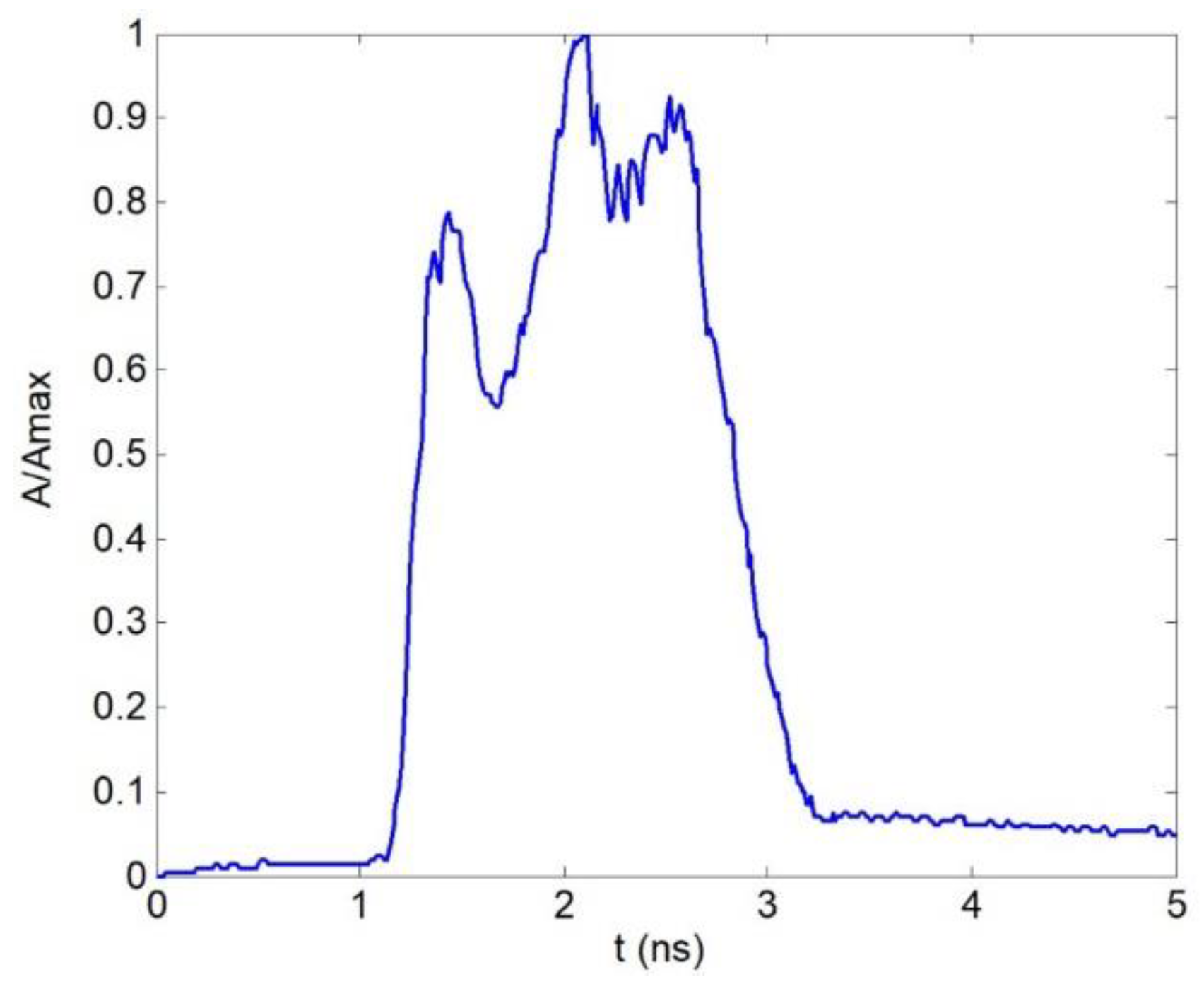
6. Pulse Response/Differential Mode Delay Measurement

During the next set of reaches, we performed DMD map measurement for manufactured ESSR-MOF of two sample lengths (mentioned above induced chirality with 10 and 66 revolutions per meter) approximately 20 m long each by DMD analyzer workstation lab kit R2D2 [28,29]. Here the general approach of the ratified standards TIA-455-220-A/FOTP-220 and IEC 60793-2-10 was utilized, which is concerned with laser-excited optical pulse response measurements at the tested optical fiber receiving end under precision offset launching conditions. A simplified block-scheme of the experimental setup for DMD map measurement under the control of launching conditions is shown in Figure 11; a general view of the workstation and software R2D2 screenshot are demonstrated in Figure 12 and Figure 13, respectively.
The Fabry-Perot laser diode (LD) “1” generates quasi-Gaussian optical pulse at wavelength λ = 1310 nm with a full width at a half maximum (FWHM) of about 340 ps. It is pigtailed by standard single-mode (SM) optical fiber ITU-T Rec. G.652, terminated by FC/PC connector “2”. Laser-excited optical signal is launched to tested ESSR-MOF via fiber optic adaptor FC “3” and single-mode pigtail (ITU-T Rec. G.652) “4”, which is spliced with ESSR-MOF under precision offset by fusion splicer “5” via program “Attenuator”. Here, parameter “Attenuation” is set to 0, “offset”—to desired value (µm), and “ECF factor” (surface tension compensation factor) also is set to 0 to avoid deformations in the heat zone of the offset fusion splice. The measured spectrum of DMD analyzer LD is shown in Figure 14. Reference optical signal (measured via short SM patch-cord) with overlapped Gaussian pulse is represented in Figure 15. The receiver end of the ESSR_MOF sample is pigtailed by multimode optical fiber (MMF) Cat. OM2+/OM3 with also FC/PC connector. Therefore, the optical pulse passes to the DMD analyzer receiver “10” from the above- described pigtailed output ESSR-MOF “7” via fiber optic adaptor FC “8” and also MMF pigtail FC/PC “9”.
The results of the DMD map measurement with 1.0 μm intervals of the offset launching over ranges 0–8.0 μm and 0–14.0 μm are demonstrated in Figure 16. For the weak induced chirality sample of ESSR-MOF, the optical pulse keeps its envelope without any DMD distortions over the whole researched offset range, while for ESSR-MOF with twisting, 66 revolutions per meter optical pulse splits under strong offset launching conditions.
We estimated the optical pulse response FHWM by a well-known method [30] for signal analysis with arbitrary form. Results of the computation of FHWM dependance on offset are represented in Figure 17. Here weakly chiral ESSR-MOF shows low FWHM increasing, which is not more than 50 ps, while strongly-twisted ESSR-MOF provides FHWM growing up to 200–250 ps in comparison with centralized launching conditions. The described results may imply the potentiality of strong mode mixing and power diffusion effects with offset improvement.
For the next series of tests, we modified the setup by placing the spool “11” with MMF 50/125 (approximately 508 m length) between the ESSR-MOF sample “6” and laser source “1” of DMD analyzer workstation R2D2 (Figure 18). We considered old generation MMF of Cat. OM2 [28,29,31] with strong DMD effect appearance: The pulse splits on two components under DMD of more than 500 ps after the reference pulse propagation over-declared MMF of 500 m length. The graded refractive index profile of the above-mentioned MMF is represented in Figure 19. It differs by great technological defect (dip) in the core center and local fluctuations of the refractive index, which is one of the main reasons for pulse splitting at the receiving end due to strong DMD effect occurring. Normalized distorted pulse response, measured at the output of this 508 m length MMF, is shown in Figure 20: Here three peaks are detected, while total DMD is 1.14 ns or per-unit length is 2.24 ns/km.
One end of the MMF spool is pigtailed by MMF 50/125 pigtail FC/PC (Figure 18), while another one end is jointed to the tested ESSR-MOF sample “6” via fusion splicer “5” with precision offset. Figure 21 represents the results of DMD map measurement during the connection of the described combined link to laser source (“Transmitter” (Tx) end) via MMF Cat. OM2 spool “11”, and “receiver” (Rx) end—via tested ESSR-MOF “2”. During the next step, we reversely reconnected the link: ESSR-MOF was installed at the Tx end, and MMF spool at the Rx end. Results are demonstrated in Figure 22. Analysis of DMD map measurement results demonstrates a good potentiality of presented ESSR-MOF for applications in fiber optic devices for selected mode group DMD management: Depending on the placement of ESSR-MOFs (Tx or Rx end), it is able to impact on the DMD appearance character as well as the amplitude and/or delay of the particular mode/mode group.

7. Conclusions

This work presents designed and fabricated samples of new 125-µm silica ESSR-MOFs, differing by special equiangular spiral six-ray geometry and induced chirality with twisting 10 and 66 revolutions per meter. Some technical aspects of implementation on the practice technique for twisted MOF manufacturing by rotating the cane during MOF drawing are reported. We performed numerical analysis for fabricated ESSR-MOF pilot samples by rigorous numerical finite element method. Here, digitalized MOF end face images were used as initial data. Numerical analysis of researched ESSR-MOF allowed to detect six modes, satisfying cut-off conditions, got their radial field distributions and estimated values of their effective refractive index. We performed a series of tests concerned with spectral and pulse responses. Here, ESSR-MOF attenuation is less than 2.5 dB/km over the whole “C”-band for both samples with weak and strong chirality, while at λ = 1310 nm it is less than 3.6 and 5.1 dB/km, respectively. During the next step, DMD maps were measured, according to the general approach of ratified standards TIA-455-220-A/FOTP-220 and IEC 60793-2-10, after the reference pulse propagation over the tested ESSR-MOF sample, as well as over the combined fiber optic link, containing 500 m length spool of MMF Cat. OM2 with strong DMD appearance, connected by fusion splicer to ESSR-MOF with precision offset. Analysis of measured DMD maps demonstrated a good potentiality of presented ESSR-MOFs for applications in fiber optic devices for selected mode group DMD management. Depending on the placement of ESSR-MOF (Tx or Rx end) and its chirality order, it is able to impact on DMD appearance character as well as the amplitude and/or delay of the particular mode/mode group. However, detailed research of ESSR-MOF properties under utilization in various applications in measurements/sensors or/and laser systems, telecommunications etc. require an additional series of tests and experiments in future works.

Author Contributions

Conceptualization, A.V.B., V.V.D., G.S., M.T., V.J.; methodology, A.V.B., V.A.B., K.V.D., Y.I., O.G.M., F.P., J.Y.; development of technique for twisted optical fiber fabrication, modification of drawing tower, chiral microstructured optical fiber fabrication, V.V.D., K.V.D., A.V.K., A.S.M., G.A.P., E.V.T.-N.; measurements of geometry parameters, laser beam profile, attenuation, V.V.D., A.V.K., A.S.M., G.A.P., E.V.T.-N.; measurements of DMD maps, A.V.B., A.Y.B., M.V.D., A.S.E., A.A.K., A.Z.S., E.S.Z.; writing—review and editing, A.V.B.; visualization, A.V.B., V.V.D., M.V.D.; supervision, A.V.B.; project administration, A.V.B. All authors have read and agreed to the published version of the manuscript.

Funding

This research was funded by RFBR, DST, NSFC and NRF according to the research project 19-57-80016 BRICSt.

Institutional Review Board Statement

Not applicable.

Informed Consent Statement

Not applicable.

Data Availability Statement

The data presented in this study are available on request from the corresponding author. The data are not publicly available due to they are still collected, compared and analyzed for the set of fabricated pilot samples of twisted MOFs with various configuration.

Conflicts of Interest

The authors declare no conflict of interest. The funders had no role in the design of the study; in the collection, analyses, or interpretation of data; in the writing of the manuscript, or in the decision to publish the results.

References

  1. Barlow, A.J.; Ramskov-Hansen, J.J.; Payne, D.N. Birefringence and polarization mode dispersion in spun single-mode fibers. Appl. Opt. 1981, 20, 2962–2968. [Google Scholar] [CrossRef] [PubMed]
  2. Hart, A.C., Jr.; Huff, R.G.; Walker, K.L. Method of Making a Fiber Having Low Polarization Mode Dispersion Due to a Permanent Spin. U.S. Patent 5298047, 29 March 1994. [Google Scholar]
  3. Blaszyk, P.E.; Christoff, W.R.; Gallagher, D.E.; Hawk, R.M.; Kiefer, W.J. Method and Apparatus for Introducing Controlled Spin in Optical Fibers. U.S. Patent 6324872 B1, 4 December 2001. [Google Scholar]
  4. Li, M.-J.; Chen, X.; Nolan, D.A. Fiber spinning for reducing polarization mode dispersion in single-mode fibers: Theory and applications. Proc. SPIE 2003, 5247, 97–110. [Google Scholar]
  5. DiGiovanni, D.J.; Golowich, S.E.; Jones, S.L.; Reed, W.A. Method of Making an Improved Multimode Optical Fiber and Fiber Made by Method. U.S. Patent 2001/0019652, 16 May 2001. [Google Scholar]
  6. DiGiovanny, D.J.; DiMarcello, F.V.; Jiang, X.L.; Oulundsen, G.E.; Pandit, S.P. Multimode optical Fiber with Increased Bandwidth. U.S. Patent 2004/0228590 A1, 18 November 2004. [Google Scholar]
  7. Koponen, J.; Sosnowki, T.; Ye, C. Spun Non-Circular and Non-Elliptical Core Optical Fibers and Apparatuses Utilizing the Same. U.S. Patent US2014268310A1, 18 September 2014. [Google Scholar]
  8. Koska, P.; Peterka, P.; Doya, V. Numerical modeling of pump absorption in coiled and twisted double-clad fibers. IEEE J. Sel. Top. Quantum Electron. 2016, 22, 4401508. [Google Scholar] [CrossRef]
  9. Wong, G.K.L.; Beravat, R.; Russell, P.S.J. Helically twisted photonic crystal fibres. Philos. Trans. R. Soc. A Math. Phys. Eng. Sci. 2017, 375, 20150440. [Google Scholar]
  10. Fuochi, M.; Hayes, J.R.; Furusawa, K.; Belardi, W.; Baggett, J.C.; Monro, T.M.; Richardson, D.J. Polarization mode dispersion reduction in spun large mode area silica holey fibres. Opt. Express 2004, 12, 1972–1977. [Google Scholar] [CrossRef] [Green Version]
  11. Weiss, T.; Wong, G.K.L.; Biancalana, F.; Barnett, S.M.; Xi, X.M.; Russell, P.S.J. Topological Zeeman effect and circular birefringence in twisted photonic crystal fibers. J. Opt. Soc. Am. B 2013, 30, 2921–2927. [Google Scholar] [CrossRef] [Green Version]
  12. Xi, X.M.; Weiss, T.; Wong, G.K.L.; Biancalana, F.; Barnett, S.M.; Padgett, M.J.; Russell, P.S.J. Optical activity in twisted solid-core photonic crystal fibers. Phys. Rev. Lett. 2013, 110, 143903. [Google Scholar] [CrossRef] [PubMed] [Green Version]
  13. Wong, G.K.L.; Xi, X.M.; Frosz, M.H.; Russell, P.S.J. Enhanced optical activity and circular dichroism in twisted photonic crystal fiber. Opt. Lett. 2015, 40, 4639–4642. [Google Scholar] [CrossRef] [PubMed]
  14. Alexeyev, C.N.; Lapin, B.P.; Milione, G.; Yavorsky, M.A. Optical activity in multihelicoidal optical fibers. Phys. Rev. A 2015, 92, 033809. [Google Scholar] [CrossRef]
  15. Alexeyev, C.N.; Lapin, B.P.; Milione, G.; Yavorsky, M.A. Resonance optical activity in multihelicoidal optical fibers. Opt. Lett. 2016, 41, 962–965. [Google Scholar] [CrossRef] [PubMed]
  16. Xi, X.M.; Wong, G.K.L.; Weiss, T.; Russell, P.S.J. Measuring mechanical strain and twist using helical photonic crystal fiber. Opt. Lett. 2013, 38, 5401–5404. [Google Scholar] [CrossRef]
  17. Bohnert, K.; Gabus, P.; Kostovic, J.; Brandle, H. Optical fiber sensors for the electric power industry. Opt. Lasers Eng. 2005, 43, 511–526. [Google Scholar] [CrossRef]
  18. Ma, X.; Zhu, C.; Hu, I.-N.; Kaplan, A.; Galvanauskas, A. Single-mode chirally-coupled-core fibers with larger than 50 μm diameter cores. Opt. Express 2014, 22, 9206–9219. [Google Scholar] [CrossRef] [PubMed]
  19. Wong, G.K.L.; Kang, M.S.; Lee, H.W.; Biancalana, F.; Conti, C.; Weiss, T.; Russell, P.S.J. Excitation of orbital angular momentum resonances in helically twisted photonic crystal fiber. Science 2012, 337, 446–449. [Google Scholar] [CrossRef]
  20. Willner, A.E.; Huang, H.; Yan, Y.; Ren, Y.; Ahmed, N.; Xie, G.; Bao, C.; Li, L.; Cao, Y.; Zhao, Z.; et al. Optical communications using orbital angular momentum beams. Adv. Opt. Photonics 2015, 7, 66–106. [Google Scholar] [CrossRef] [Green Version]
  21. Barshak, E.V.; Alexeyev, C.N.; Lapin, B.P.; Yavorsky, M.A. Twisted anisotropic fibers for robust orbital-angular-momentum-based information transmission. Phys. Rev. A 2015, 91, 033833. [Google Scholar] [CrossRef]
  22. Stefani, A.; Kuhlmey, B.T.; Fleming, S. Orbital angular momentum modes by twisting of a hollow core antiresonant fiber. In Proceedings of the 2017 European Conference on Lasers and Electro-Optics and European Quantum Electronics Conference, Munich, Germany, 25–29 June 2017. [Google Scholar]
  23. Stefani, A.; Fleming, S.C.; Kuhlmey, B.T. Terahertz orbital angular momentum modes with flexible twisted hollow core antiresonant fiber. APL Photonics 2018, 3, 051708. [Google Scholar] [CrossRef] [Green Version]
  24. Napiórkowski, M.; Urbanczyk, W. The effect of coupling between core and cladding modes in twisted microstructured optical fibers. Proc. SPIE 2018, 10681, 106810H. [Google Scholar] [CrossRef]
  25. Fu, C.; Liu, S.; Wang, Y.; Bai, Z.; He, J.; Liao, C.; Zhang, C.; Zhang, F.; Yu, B.; Gao, S.; et al. High-order orbital angular momentum mode generator based on twisted photonic crystal fiber. Opt. Lett. 2018, 43, 1786–1789. [Google Scholar] [CrossRef] [PubMed] [Green Version]
  26. Cui, Y.; Ye, J.; Li, Y.; Dai, P.; Qu, S. Vortex chirality-dependent filtering in helically twisted single-ring photonic crystal fibers. Opt. Express 2019, 27, 20816–20823. [Google Scholar] [CrossRef]
  27. Zhou, G.; Liu, J.; Xia, C.; Hou, Z. Orbital-angular-momentum-amplifying helical vector modes in Yb3+-doped three-core twisted microstructure fiber. Opt. Express 2020, 28, 21110–21120. [Google Scholar]
  28. Bourdine, A.V. Differential mode delay of different generations of silica multimode optical fibers. Photon Express 2008, 5–6, 20–22. [Google Scholar]
  29. Bourdine, A.V. On multimode optical fiber DMD diagnostics. Inforcomm. Tech. 2008, 6, 33–38. [Google Scholar]
  30. Gowar, J. Optical Communication Systems; Prentice Hall/International/Radio i Svyaz (Radio and Communications): Moscow, Russia, 1989. [Google Scholar]
  31. Bottacchi, S. Multi-Gigabit Transmission over Multimode Optical Fibre: Theory and Design Methods for 10GbE Systems; JohnWiley & Sons Ltd.: New York, NY, USA, 2008. [Google Scholar]
Figure 1. Modifications of the drawing tower feed unit: (a) top of the feed unit with installed stepper motor, which rotates a preform under the desired speed; (b) completed and jointed fluoroplastic rotational adapter with installed MOF cane; (c) the bottom of the feed unit, which chuck holds the rotational adapter and rotates a cane; (d) bottom part of fluoroplastic rotational adapter (inside), fixed in the feed unit chuck.
Fibers 09 00027 g001
Figure 2. Modifications of drawing tower: (a) general view of the drawing tower feed unit; (b) general view of drawing tower.
Fibers 09 00027 g002
Figure 3. ESSR-MOF: (a) cross-section sketch; (b) MOF prepared cane (outer diameter 3 mm); (c) image of fabricated ESSR-MOF end (outer diameter 125 µm).
Fibers 09 00027 g003
Figure 4. Image of twisted ESSR-MOF fragments: (a) 10 revolutions per meter; (b) 66 revolutions per meter.
Fibers 09 00027 g004
Figure 5. Near-field measurements of laser beam profile (wavelength λ = 1550 nm) under various receiving conditions after propagation of the manufactured sample of ESSR-MOF with induced chirality of 66 revolutions per meter and length 20 m: (ad) the smallest-sized air holes (air hole diameter to the pitch ratio is 0.90); (eh) the maximal size of air holes (air hole diameter to the pitch ratio is 0.95); (a,d)—ESSR-MOF end face is placed in the focus of the camera lens; (b)—ESSR-MOF end face is also placed in the focus of the camera lens, receiving is performed via phase plate; (c)—ESSR-MOF end face is placed outside the focus of the camera lens; (c,e) ESSR-MOF end face is placed outside the focus of the camera lens; (f)—ESSR-MOF end face is placed outside the focus of the camera lens, image is focused via outer lens.
Fibers 09 00027 g005
Figure 6. Attenuation of manufactured ESSR-MOF samples with induced chirality: (a) 10 revolutions per meter; (b) 66 revolutions per meter.
Fibers 09 00027 g006
Figure 7. Overall dimensions of manufactured ESSR-MOF sample with chirality of 66 revolutions per meter: (a) outer diameter; (b) core diameter.
Fibers 09 00027 g007
Figure 8. Dimensions of 2D-structure of the manufactured ESSR-MOF sample with chirality of 66 revolutions per meter: (a) air holes; (b) pitches.
Fibers 09 00027 g008
Figure 9. Computed radial distributions of guided mode fields.
Fibers 09 00027 g009
Figure 10. Diagram of distribution of the effective refractive index over guided modes.
Fibers 09 00027 g010
Figure 11. Simplified block scheme of DMD analyzer workstation R2D2 (ESSR-MOF DMD map measurement setup).
Fibers 09 00027 g011
Figure 12. General view of DMD analyzer workstation R2D2: “3” is “Tx” fiber optic adaptor FC; “4” is “Tx” pigtail FC/PC; “5” is fusion splicer (offset connection of “Tx” pigtail and tested optical fiber); “6” is tested optical fiber; “7” is “Rx” pigtail FC/PC; and “8” is “Rx” fiber optic adaptor FC.
Fibers 09 00027 g012
Figure 13. DMD analyzer workstation R2D2 software screenshot: “1” is the reference pulse; “2” is the pulse response at the output of tested optical fiber; “3” is the amplitude-frequency modulation response of the reference pulse; “4” is the amplitude-frequency modulation response of the distorted pulse; and “5” is the resulting sum amplitude-frequency modulation response.
Fibers 09 00027 g013
Figure 14. Optical spectrum of DMD analyzer Fabry-Perot LD.
Fibers 09 00027 g014
Figure 15. Reference optical pulse.
Fibers 09 00027 g015
Figure 16. DMD map of 20 m length chiral ESSR-MOF sample: (a) 10 revolutions per meter; (b) 66 revolutions per meter.
Fibers 09 00027 g016
Figure 17. Optical pulse response FWHM dependance on offset: (a) 10 revolutions per meter; (b) 66 revolutions per meter.
Fibers 09 00027 g017
Figure 18. Modified setup for DMD map measurements: spool with MMF Cat. OM2 “11” (Tx) and tested ESSR-MOF “6” (Rx) with precision offset between optical fiber centers.
Fibers 09 00027 g018
Figure 19. Graded refractive index profile of the tested MMF of Cat. OM2.
Fibers 09 00027 g019
Figure 20. Optical pulse response at the output of MMF.
Fibers 09 00027 g020
Figure 21. DMD map of combined link, containing 500 m length of MMF Cat. OM2 (Tx) and 20 m length of chiral ESSR-MOF (Rx): (a) 10 revolutions per meter; (b) 66 revolutions per meter.
Fibers 09 00027 g021
Figure 22. DMD map of combined link, containing 20 m length of chiral ESSR-MOF (Tx) and 500 m length of MMF Cat. OM2 (Rx): (a) 10 revolutions per meter; (b) 66 revolutions per meter.
Fibers 09 00027 g022
Publisher’s Note: MDPI stays neutral with regard to jurisdictional claims in published maps and institutional affiliations.

