Abstract
The technical process of the synthesis of a fluorophosphosilicate (FPS) glass core was thoroughly investigated for the first time utilizing a modified chemical vapor deposition (MCVD) all-gas-phase fabrication method. It was discovered that the limiting doping level of the silica glass simultaneously co-doped with phosphorus (P) and fluorine (F) was found to be confined by the formation of POF3 gas. The dopants content was achieved as high as 4.7 at% of P and 1.1 at% of F in a glass core, respectively. A developed “in-house” manufacturing method makes it possible to fabricate a large mode area (LMA) purely single-mode Er–Yb co-doped optical fibers with a core diameter of 20 μm and with a lasing efficiency comparable to commercially available LMA Er–Yb optical fibers.
1. Introduction
The emission wavelength range in the vicinity of 1.5 μm is “eye-safe” (as compared to the 1 μm spectral range of Yb-doped fiber lasers), which overlaps with the maximum optical transparency of silica glass and is widely used in various practical applications, i.e., related to signal propagation in the atmosphere, such as LIDAR (light detection and ranging). The most common sources of laser radiation at a wavelength of 1.5 μm are typically silica fiber lasers and amplifiers based on double-clad optical fibers of an Er2O3–Yb2O3–P2O5–SiO2 glass core composition. In this particular fiber design, Yb3+ ions are capable of efficiently absorbing the pump power (915/980 nm) from the first reflective cladding and transfer energy to Er3+ ions. The maximum efficiency of the energy transfer of excitation (ETE) from Yb3+ to Er3+ ions is particularly observed in the phosphosilicate glass matrix, due to the rapid relaxation of Er3+ ions from the level to which the energy is transferred from Yb3+ ions and reverse energy transmission is almost excluded.
A high concentration of Yb dopant (0.75–1 at%) ensures the efficient pump absorption, and in addition, suppresses Er dopant clustering (through isolating neighboring Er3+ ions and thus reducing the up-conversion energy transfer) [1]. In turn, to dissolve such a large amount of Yb2O3, at least 6.7–8 at% of P is required. However, the sufficiently high refractive index of this glass (numerical aperture (NA)~0.2) imposes a reduction in the core diameter in a single-mode fiber (4–7 μm) and an increase in the active fiber length (5–20 m) for maintaining efficient pump absorption. As a result, the threshold of nonlinear effects is dramatically reduced, which limits the output power of lasers to ~100 W [2], and eventually Er–Yb-co-doped fibers are not used for designing pulsed laser sources.
In fact, the fiber core diameter can be increased by increasing the reflecting cladding refractive index. For example, Nufern developed an Er–Yb optical fiber (LMA-EYDF-25P/300-HE) with an enlarged core diameter of 25 μm. Our measurements of a refractive index profile and glass composition have revealed that a low core-to-first-cladding NA was achieved in this fiber by the deposition of a massive germanosilicate cladding around the core (utilization of a pedestal design). The refractive indexes difference of core and cladding glasses (Δn) in this fiber was ~0.005. This fiber design provided 200 W of output power with a pump-to-signal conversion efficiency (PCE) of 50% in respect to [3]. However, it should be noted that the pedestal structure is limited in its parameters since the design suffers high mechanical stresses introduced in preforms (due to the significant difference in coefficients of the thermal expansion of core and cladding glasses) and pretty complicated in manufacturing. As a result, the cutoff wavelength of the first higher mode (LP11) exceeds 2.8 μm, and in the 1.5 μm region, the fiber developed in Nufern is multimode.
In this paper, we propose another possible solution for lowering fiber structure NA, namely, we are targeting to increase the fiber single-mode core diameter by reducing the glass core refractive index. In general, there are only two well known dopants that reduce the silica glass refractive index: these dopants are B2O3 and F. In Er–Yb fibers, co-doping with B2O3 is highly undesirable, since the tail of the intense B–O bond band centered at 7 μm narrows the glass transparency window down to 1.3 μm, since overlapping the 1.5 μm range. In contrast to B2O3 dopant, the addition of F reduces the refractive index of silica glass by an order of magnitude, moreover, this approach is obviously more efficient and does not impair silica glass transparency.
The maximum achieved concentration of P in phosphosilicate glasses fabricated by the modified chemical vapor deposition (MCVD) method is ~11.4 at% and this concentration corresponds to an increase in Δn by 0.015 [4]. The maximum of F content in fluorosilicate glasses is limited to ~3.2 at% and provides a decrease in Δn by –0.012 [5]. Theoretically, in F–P2O5–SiO2 co-doped glass containing 6.71 at% of P and 3.2 at% of F, the calculated Δn should not be higher than –0.003, which potentially makes it possible to introduce into the glass matrix ~0.75–0.88 at% of rare-earth elements (REE) and keeps Δn as low as ~0.003–0.004 (0.125 at% of REE corresponds Δn~0.001 in respect to [6]). However, to date, fluorophosphosilicate (FPS) glasses with high content of P and F co-doping have not been implemented. Previously, we already fabricated FPS glasses using C2F3Cl3 as F precursor and containing 9.39 at% of P and 0.32 at% of F [7]. The relatively high refractive index of the glass did not allow this glass to be used as a core material for single-mode LMA optical fibers. Moreover, FPS glasses with a refractive index close to that of silica glass (0.64 at% of F and 1 at% of P) are widely used as a cladding material in optical fiber preforms fabrication, however, this glass composition is also not suitable as the core glass matrix for Er–Yb co-doping due to the low P concentration itself.
This paper presents the results of our systematical studies on the fabrication of Er2O3–Yb2O3–F–P2O5–SiO2 glasses (Er–Yb–FPS) co-doped with a high concentration of P and F simultaneously. The technical process of the synthesis of FPS glass core performs utilizing the MCVD all-gas-phase deposition method was investigated in detail. The developed FPS glass matrix allows manufacturing an LMA single-mode Er–Yb co-doped fibers with PCE efficiency comparable to commercially available LMA fibers (particularly with Nufern LMA-EYDF-25P/300-HE).
2. Materials and Methods
The developed fiber preforms were fabricated utilizing an MCVD all-gas-phase deposition method. In the deposition process, Heraeus reference tubes with an outer diameter of 15 mm were used. High-purity SiCl4, POCl3, O2, Er(thd)3 and Yb(thd)3 (thd = 2,2,6,6-tetramethyl-3,5-heptanedionate) were used as precursors. The low-volatile Er(thd)3 and Yb(thd)3 powders were loaded in glass containers and thermostat controlled at 160 °C. To exclude preliminary condensation as well as an interaction between the metal organic materials and other precursors, the REE chelates vapors were delivered into the deposition zone through a separate heated line.
In general, a number of F precursors may be used in the MCVD method: CF2Cl2, C2F3Cl3, SF6, CF4. All these compounds acting as a fluorinating reagent interacting with SiO2, namely quantitatively forming SiF4, and the reaction can be described as follows:
4C2F3Cl3 + 3SiO2 + 5O2↑ = 3SiF4↑ + 8CO2↑ + 6Cl2↑
3SiO2 + SiF4↑ = 4SiO1.5F
In order to exclude the etching process and increase the efficiency of F-doped glass deposition, SiF4 (high purity grade) was used as a F precursor in our experiments.
After the fabrication process, the refractive index profiles (RIPs) in the preforms were measured using Photon Kinetics PK2610 analyzer. The York Technology S14 analyzer used for performing RIP measurements in corresponding optical fibers. The elemental composition of the deposited glasses determined using thin preform slices (thickness ~2 mm) by energy dispersive x-ray spectroscopy (JEOL 5910LV).
3. Discussion
3.1. Standard All-Gas-Phase Deposition
In our first experiments, we made an attempt to synthesize Er–Yb–FPS glass by the deposition technique initially proposed in [8] which was used for the fabrication of active aluminosilicate fiber preforms utilizing REE(thd)3 precursors (chelate compounds). For this purpose, the vapors of SiCl4, POCl3, SiF4, Er(thd)3, Yb(thd)3 were mixed together with oxygen and delivered into the hot zone. However, during the sintering of the deposited “soot” of the F/Er2O3/Yb2O3/P2O5/SiO2 glass composition it was revealed that intense bubble formation (as depicted in Figure 1), though the F–Yb2O3–Al2O3–SiO2 glasses synthesized by the same approach and using SiF4 precursor were manufactured without any defects [9].
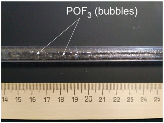
Figure 1.
The photo of a tubular preform with the inner layer of Er–Yb–fluorophosphosilicate (FPS) glass fabricated by the standard modified chemical vapor deposition (MCVD) all-gas-phase deposition technique. The source of bubbles in FPS glass is POF3.
The bubbles appearance can be explained by the formation of highly volatile products due to the interaction between Er–Yb–FPS glass components at the stage of soot melting in the MCVD deposition process. The incorporation of F into silica glass proceeds through the formation of SiO1.5F particles (as per reaction 2, see above). In fact, F is strongly bonded to Si and the melting of the SiO2/SiO1.5F layer proceeds without the formation of SiF4 in the deposited glass. The introduction of additional dopants into the glass structure reduces the strength of the silica glass network, facilitating a chemical interaction among the individual components. For example, in melted Yb2O3–F–Al2O3–SiO2 glass, the formation of AlF3 and YbF3 is obviously possible. However, these fluorides have low volatility [10], in contrast to POF3 (it is a gas under normal conditions), the formation of which, to the best of our knowledge, is the clear reason for the “boiling up” effect during the MCVD deposition of the Er–Yb–FPS glass.
For the detailed investigation of the technical process conditions, a thermodynamic modeling of the process of transformation of a vapor–gas mixture into glass particles was carried out using the Chemical Thermodynamics Calculator software complex by a standard technique described in [11]. According to the performed calculation, in addition to SiO1.5F (SiO2 + SiO1.5F≡Si2O3.5F) adducts, the condensed glass layer contains an additional F-containing phase, namely YbF3 (Figure 2).
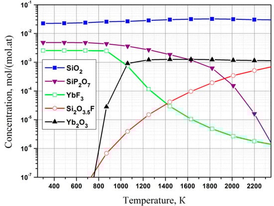
Figure 2.
The temperature dependence of condensed phase compositions simulated for the initial gas mixture SiCl4 + 1.26SiF4 + 0.18POCl3 + 0.1Yb(thd)3 + 7.5O2 at a pressure of 1 atm.
Despite a lower concentration of YbF3 relative to SiO1.5F content in the temperature range of glass synthesis typical for MCVD (1500–1800 K), each YbF3 particle contains three times more F. The sintering of this highly fluorinated layer proceeds with the formation of a POF3 compound, which freezes in the form of bubbles in the deposited glass while the viscosity of the glass layer rises. Another disadvantage of the standard all-gas-phase deposition technique is that the introduction of a high concentration of REE into glass is difficult due to the low volatility of Er(thd)3 and Yb(thd)3 precursors (vapor pressure is less than 1 mm Hg even at a temperature of 160 °C).
3.2. Improved All-Gas-Phase Deposition Technique
In order to exclude bubble formation and secure a high concentration of REE in Er–Yb–FPS glass, we used the same technological approach already demonstrated earlier in [12] for the manufacture of active aluminophosphosilicate fibers. This technical process utilizes a two-step fabrication process where the separate deposition of a core glass layer followed by so-called gas-phase impregnation with REE oxides by several main burner passes.
In our experiments, the FPS glass core of different compositions was deposited by using a standard all-gas-phase deposition technique. For this purpose, fixed flows of SiCl4 and POCl3 were used, but different fractions of SiF4 were added into the initial gas mixture. If vapors of Er(thd)3 and Yb(thd)3 were not added, sintering the deposited F/P2O5/SiO2 soot into a transparent glass layer proceeded without bubble formation. As depicted in Figure 3a, with an increase in SiF4 flow, the F concentration in glass increased, but the P content sharply decreased. The maximum F concentration of ~ 1.1 at% is achieved at a volume fraction of SiF4 ~ 0.03 and a further increase in SiF4 flow only leads to a decrease in P concentration, while the F content nearly does not change in the glass. The obtained dependence can obviously be explained by the formation of a volatile POF3 adduct and the complexity of its retention in the deposited glass.
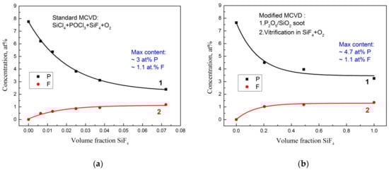
Figure 3.
The dependence of P concentration (curve 1) and F concentration (curve 2) in the FPS glass matrix on the volume fraction of SiF4 gas. The glasses were fabricated: (a) by the standard all-gas-phase deposition technique; (b) utilizing improved deposition technique.
Utilizing the MCVD method in [4], silica glasses with the maximal F content were obtained. The glasses were manufactured by means of amorphous SiO2 layer (aerosil) sintering in 100% (pure) SiF4 atmosphere. That is why, to investigate the possible level of fluorination of phosphosilicate glasses by this approach, the following experiment was carried out. At first, a P2O5/SiO2 soot layer was deposited by a reverse pass (the main burner was moving in the opposite direction to the gas mixture flow). The layer composition and thickness were chosen at the same as it was used in the described above standard all-gas-phase deposition method (with a high content of P, more than 7.38 at%). Then, the layer was treated at the same temperature, but with different fractions of SiF4 in the gas mixture. As depicted in Figure 3b, the dependence we achieved is similar to the standard technique, with the only difference that at a F concentration of ~1.1 at% in the glass, significantly more P (near~4.7 at%) remains in the glass core. In this case, obviously that POF3 is formed only during the soot sintering, in contrast to the standard procedure, where POF3 is additionally formed due to the interaction of SiF4 and POCl3 precursors in the initial gas mixture, and accordingly this leads to a greater loss of P2O5. An increase in the thickness of the deposited layer and a simultaneous increase in the SiF4 and POCl3 flows in the vapor–gas mixture did not contribute to an increase in the concentration of F and P in the deposited glass. Thus, we can conclude that the achieved level of simultaneously doping of ~1.1 at% F and ~4.7 at% P is the limiting one for the MCVD method. Eventually, exactly this composition of the FPS glass matrix was used in our work to fabricate active Er–Yb co-doped fibers.
The active fiber preforms were fabricated by using an improved technical process (a schematically drawing of the technical process is depicted in Figure 4) as follows.
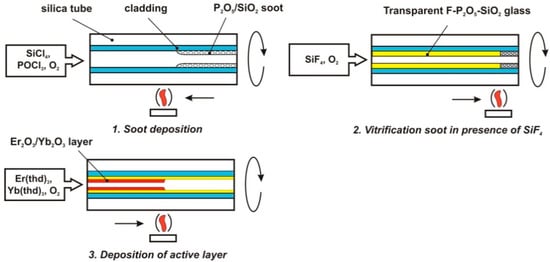
Figure 4.
The schematically illustrated improved Er–Yb–FPS glass core fabrication process.
Once the P2O5/SiO2 soot was deposited and sintered in the SiF4 gas flow, Er2O3 and Yb2O3 particles were deposited on the surface of the FPS glass layer by multiple (3–4) burner passes using Er(thd)3 and Yb(thd)3 precursors. To remove the hydrogen-containing impurities, CCl4 gas was added into the vapor’s mixture. The stage of the high-temperature fusion of these two layers (deposited FPS glass layer and Er2O3/Yb2O3 co-doped layer) was excluded to prevent extra evaporation of P and F. A core with a diameter of 2 mm was fabricated by applying a 10–12 thin double layers deposition procedure as described above. The alignment of the glass composition over the core cross section occurred due to diffusion processes of the core components at the stage of preform collapse as well as during fiber drawing. As depicted in Figure 5, the layered shape of the refractive index profile noticed in the preform was completely smoothed in the corresponding fiber.
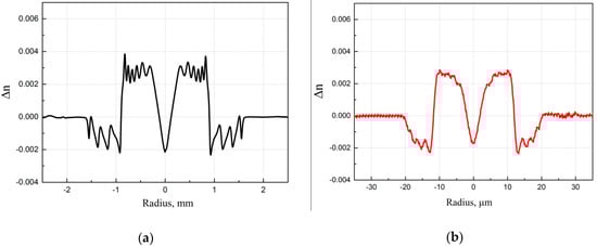
Figure 5.
The refractive index profiles (RIPs) measured in a preform (a) and in a corresponding fiber (b). The preform with an Er–Yb–FPS glass core was manufactured by the improved all-gas-phase deposition technique (ASL-116).
A central dip in the RIP is due to the evaporation of P2O5 during the preform collapse process. There are approaches to its elimination [13], but in this work, they were not used, and rare-earth oxides were not introduced into the central part of the core since this topic is our target for future research.
3.3. Fibers Characterization
Erbium dopant concentration in Er–Yb co-doped fibers is typically limited to ~ 0.05 at% (due to concentration quenching) and has no effect on the refractive index of a core glass or on the level of background losses. In the opposite case, a Yb dopant concentration is required as high as possible for achieving the efficient pump absorption and suppression of Er3+ ions clustering. However, the maximal Yb concentration is limited by the appearance of a separate Yb-rich phase in glass (phase separation) and eventually this introduces higher optical losses in fibers [14]. The limiting concentration of Yb in the developed FPS glass matrix was investigated based on optical loss measurements in a series of fibers doped with 0.02–0.44 at% Yb, 0.96–1.1 at% F, and 4.36–4.7 at% P. As depicted in Figure 6, if the Yb concentration is more than 0.25 at%, a sharp increase in optical losses is observed (up to the level of 2–3 dB/m). Note that optical losses were measured at a wavelength of 1200 nm, where absorption of Yb and Er ions is negligible.
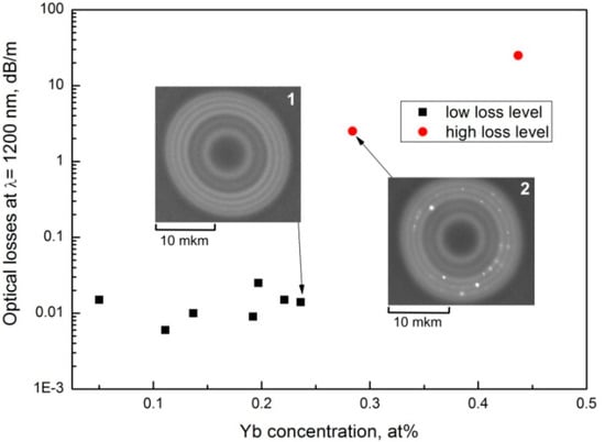
Figure 6.
The dependence of optical losses in fabricated fibers on the concentration of Yb in an Er–Yb–FPS glass core. Inserts: the photograph of a fiber core doped with 0.24 at% Yb (1) and 0.29 at% Yb (2).
As depicted in the same Figure 6, an image of the core containing 0.29 at% of Yb clearly shows the regions of a separate Yb-rich phase (a source of high scattering losses). It should be noted that the presence of up to 0.05 at% of Er in the glass matrix does not affect the Yb-dopant phase separation tendency. In particular, the optical losses in a fiber doped with 0.24 at% Yb and 0.05 at% Er measured 14 dB/km, while in a fiber containing 0.29 at% Yb and 0.004 at% Er, the optical losses were ~2.5 dB/m. Eventually, from the performed measurements, it can be concluded that the concentration limit of Yb in the developed FPS glass matrix (4.7 at% P and 1.1 at% F) is only~0.25 at%.
To determine the optimal ratio of the Er and Yb concentrations, a series of preforms with different concentration ratios of the rare-earth oxides was fabricated. The preforms were polished to a square cross-section (for better pump absorption) from which single-mode double-clad fibers with a 20 μm core and an average cladding diameter of 125 μm were then drawn. The amplification properties of the fibers based on FPS glass matrix were investigated in comparison with the commercially available Nufern fiber (LMA-EYDF-25P/300-HE) [15,16]. Below, we discuss the most significant details of this study, which explain benefits of the developed FPS glass matrix.
The most important parameter of Er–Yb fibers is ETE efficiency, which determines a fraction of Yb3+ ions located in the close vicinity of Er3+ ions and capable of transferring pump energy to them. Yb3+ ions, which do not participate in energy transfer to Er3+ ions, reduce the amplification efficiency of Er–Yb fibers, generating (or amplifying) spontaneous emission in the 1 μm spectral region. The ETE parameter was determined by a method similar to that published in [17]. A maximum ETE of 38% was achieved in our ASL-116 fiber with an Er concentration of about 0.04 at% and a Yb concentration of 0.11 at%. PCE measured in the developed fiber in a co-propagating pump (976 nm) and signal (1555 nm) amplifier scheme (input signal power 0.6 W) was found to be ~ 19% (the same efficiency is measured for fibers with twice as high Yb content and twice as low Er content). The Nufern fiber (0.05 at% Er and 0.88 at.% Yb) demonstrated only a slightly higher amplification efficiency of 26.2% in the same amplifier scheme. It is quite interesting that the share of amplifying the spontaneous emission (ASE) near 1030 nm in the ASL-116 fiber was about 0.5%, which is quite low. We attribute this negligible ASE level to the fiber geometry—where a large core diameter of 20 μm and standard cladding diameter of 125 μm provide high pump absorption even for a low Yb concentration of 0.11 at.%. The utilization of 976 nm pump results in a comparatively short optimal fiber length of 4.5 m. Eventually, a relatively low Yb content and a short fiber length reduce gain near 1030 nm, which becomes insufficient to generate ASE even for an ETE of 38%. It is worth noting that Nufern fiber demonstrates an even lower ASE level near 1030 nm—00.05%—which could be explained by a much higher ETE (~ 90%).
The maximum PCE could be typically achieved in a laser configuration. In our study, we chose a laser resonator formed by high reflection (~99%) fiber Bragg grating (HR FBG) at 1555 nm written in a 20/125 μm passive fiber with a 0.065 core NA (to minimize splice loss with the fibers under test) and normally cleaved active fiber ends, that provided 4% Fresnel reflection. The laser scheme we used in our experiments is depicted in Figure 7a. The pump at 976 nm was coupled into the investigated fiber through the high reflection fiber Bragg grating using a Pump combiner unit (PC). The unabsorbed pump was filtered out at the output of the fiber end using a Pump stripper made directly on an Er–Yb fiber under test a few cm away from its end. Additionally, a dichroic 1550/976 nm mirror (DM) was used to filter out the unabsorbed pump unfiltered by the pump stripper (importantly, in the case of Nufern fiber, where part of the pump is propagated inside the pedestal). The optimal fiber length which provided maximal PCE was found to be 4.5 m for ASL-116 fiber and 1.5 m for Nufern fiber. Slope PCE, measured using optimal fiber length, was found to be 34 and 37% for ASL-116 and Nufern fibers, respectively (Figure 7b).
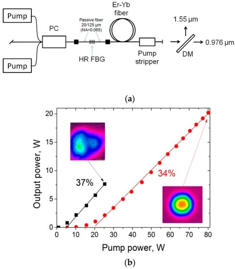
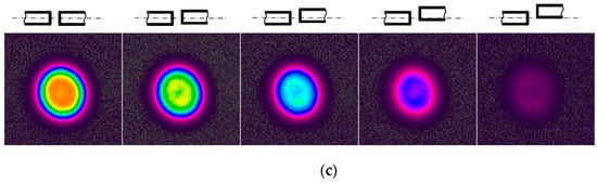
Figure 7.
(a): The laser setup scheme; (b): the dependence of the output power on the input pump power in the fibers: Nufern LMA-EYDF-25P/300-HE (black); ASL-116 (red). Inserts: the fiber ends images at a maximum output power (for Nufern fiber we have shown the image obtained for a coiling diameter of 20 cm to illustrate propagation problem in this fiber that is revealed to be a non-single mode regime); (c): the mode propagation images were obtained with a Spiricon SP-1550M camera at the output end of the unpumped ASL-116 fiber with a fiber length of about 0.5 m for different positions (shift from the fiber axis) of the excitation beam (a pump at 1555 nm from single-mode fiber SMF28 was used for excitation–and the schematic fiber’s core layout is shown above each of the corresponding mode image).
In our laser experiments, we did not pay much attention to efficient fibers cooling. However, both fibers were cooled in the same way. A shorter length of the Nufern fiber did not allow obtaining an increase in the pump power over 25 W due to insufficient heat dissipation (ignition of the fiber polymer coating). In opposition to this, in the ASL-116 fiber sample, the similar issue was not observed up to 80 W of pump power. It must be noted that the proper cooling and utilization of a longer Nufern fiber by changing the pump wavelength to 915–940 nm (where Er–Yb fibers have smaller absorption) could allow one to achieve a much higher average power of 44 W [18] and even 303 W if water cooling is applied [19]. We believe that the ASL-116 fiber sample that we fabricated by the improved fabrication method described above would also be capable of generating comparable output power if similar fiber cooling methods and sufficiently high pump power were employed.
The most important result of this study was a perfect beam quality at the output end of the ASL-116 fiber we achieved. The M2 parameter of the ASL-116 fiber did not exceed 1.1 (M2 = 1 is an “ideal” single-mode regime) within the 20 W output power range, while for the Nufern fiber, the beam quality deteriorated very quickly (M2 > 2.2 at a pump power of only 7 W for a bend diameter of 20 cm and the M2 parameter was ~1.5 for a bend diameter of 8 cm), which is a clear indicator of the non-single mode propagation regime. An improvement in the beam quality in the Nufern fiber can be achieved by tight fundamental mode excitation using bulk optical components, but even in this case, the beam quality M2 varied in the range from 1.07 to 1.4 depending on the pump power [19].
These benefits of the FPS Er–Yb fiber are accompanied by an ultimately low core NA, which was achieved in the developed fiber (0.065), and together with a depressed ring outside the core region provided a perfect single mode propagation regime (calculated cut-off wavelength was ~1.4 μm for the ASL-116 fiber sample). Eventually, the mode shape of the fabricated fiber sample does not relate to the excitation conditions, which can be clearly seen from Figure 7c, where the off-center excitation of the propagation mode only results in the reduction in output mode intensity and does not influence its shape (as compared to coaxial end-to-end excitation using the SMF28 fiber—the far-left image in Figure 7c).
4. Conclusions
The improved all-gas-phase deposition process for the manufacturing of fiber preforms based on the Er2O3–Yb2O3–F–P2O5–SiO2 glass matrix is developed and thoroughly investigated. The main limitation in the standard all-gas-phase fabrication process is the difficulties in achieving a high concentration of P and F co-doping due to POF3 gas formation. It was investigated that the POF3 compound was formed during the sintering of the deposited MCVD glass layers, as well as due to the interaction between POCl3 and SiF4 precursors in the gas mixture. The developed fabrication technique excludes the interaction of the precursors and provides a high concentration of P and F simultaneously in the deposited glass core (the maximal level of doping achieved up to 4.7 at% of P and 1.1 at% of F). Moreover, it allows fabricating a single-mode Er–Yb co-doped double-clad fiber with a core diameter of 20 μm. P concentration in the developed fibers is almost two times lower than that in typical Er–Yb fibers, which limits Yb concentration to ~0.25 at%. On the other hand, an increase in the core/cladding ratio from “standard” 5/125 to 20/125 μm made it possible to reduce the operating length of the active fibers by an order of magnitude, which in turn excluded an occurrence of parasitic lasing in the 1 μm wavelength range. In this study, despite a low ETE value of only 38%, the developed fiber exhibits a very low ASE level near 1 μm (less than 0.5% relative to output signal power) and provides PCE comparable to the best commercially available Er–Yb fiber from Nufern. In addition, the low-core NA of the developed FPS Er–Yb optical fiber provides an ideal single-mode propagation regime.
Author Contributions
Conceptualization, D.S.L., M.E.L.; formal analysis A.S.L., A.N.A., M.M.K.; investigation, D.S.L., M.E.L.; data curation, A.N.G.; software, O.G.M., writing—review and editing, A.A.U.; supervision, A.N.G., project administration, D.S.L. All authors have read and agreed to the published version of the manuscript.
Funding
Russian Science Foundation (Grant No. 20-19-00347).
Institutional Review Board Statement
Not applicable.
Informed Consent Statement
Not applicable.
Data Availability Statement
Not applicable.
Conflicts of Interest
The authors declare no conflict of interest.
References
- Kiritchenko, N.V.; Kotov, L.V.; Melkumov, M.A.; Likhachev, M.E.; Bubnov, M.M.; Yashkov, M.V.; Laptev, A.Y.I.; Guryanov, A.N. Effect of ytterbium co-doping on erbium clustering in silica-doped glass. Laser Phys. 2015, 25, 025102. [Google Scholar] [CrossRef]
- Jeong, Y.Y.; Codemard, C.A.; Nilsson, J.; Sahu, J.K.; Payne, D.N.; Horley, R.; Turner, P.W.; Hickey, L.; Harker, A.; Lovelady, M.; et al. Erbium: Ytterbium Codoped Large-Core Fiber Laser With 297-W Continuous-Wave Output Power. IEEE J. Sel. Top. Quantum Electron. 2007, 13, 573–579. [Google Scholar] [CrossRef]
- Creeden, D.; Pretorius, H.; Limongelli, J.; Setzler, S.D. Single frequency 1560 nm Er:Yb fiber amplifier with 207 W output power and 50.5% slope efficiency. In Proceedings of the SPIE 9728, Fiber Lasers XIII: Technology, Systems, and Applications, 97282L, San Francisco, CA, USA, 11 March 2016. [Google Scholar]
- Bubnov, M.M.; Dianov, E.M.; Egorova, O.N.; Semjonov, S.L.; Guryanov, A.N.; Khopin, V.F.; DeLiso, E.M. Fabrication and investigation of single-mode highly phosphorus-doped fibers for Raman lasers. In Advances in Fiber Optics; International Society for Optics and Photonics: Bellingham, WA, USA, 2000; Volume 4083, pp. 12–22. [Google Scholar]
- Guryanov, A.N.; Salganskii, M.Y.; Khopin, V.F.; Kosolapov, A.F.; Semenov, S.L. High-aperture optical waveguides based on fluorine-doped silica glass. Inorg. Mater. 2009, 45, 823–826. [Google Scholar] [CrossRef]
- Kirchhof, J.; Unger, S.; Schwuchow, A.; Jetschke, S.; Knappe, B. Dopant interaction in high power laser fibers. In Optical Components and Materials II; International Society for Optics and Photonics: Bellingham, WA, USA, 2005; Volume 5723, pp. 261–272. [Google Scholar]
- Bubnov, M.M.; Dianov, E.M.; Egorova, O.N.; Semjonov, S.L.; Guryanov, A.N.; Ketkova, L.A.; Khopin, V.F. Influence of fluorine codoping on optical losses in Ge- and P-doped fibers. In Optical Devices for Fiber Communication II; International Society for Optics and Photonics: Bellingham, WA, USA, 2001; Volume 4216, pp. 164–173. [Google Scholar]
- Tumminelli, R.P.; McCollum, B.C.; Snitzer, E. Fabrication of high-concentration rare-earth doped optical fibers using chelates. J. Lightwave Technol. 1990, 8, 1680–1683. [Google Scholar] [CrossRef]
- Abramov, A.N.; Bubnov, M.M.; Guryanov, A.N.; Lipatov, D.S.; Likhachev, M.E.; Melkumov, M.A.; Yashkov, M.V. Fabrication of Active Fluoroaluminosilicate Fibers for High-Power Fiber Lasers. Inorg. Mater. 2018, 54, 271–275. [Google Scholar] [CrossRef]
- Kirchhof, J.; Unger, S.; Kobelke, J.; Schuster, K.; Mörl, K.; Jetschke, S.; Schwuchow, A. Materials and Technologies for Microstructured High Power Laser Fibers. In Optical Fibers: Technology; International Society for Optics and Photonics: Bellingham, WA, USA, 2005; Volume 5951, p. 595107. [Google Scholar]
- Kut’in, A.M. Thermodynamic Models for Multicomponent Heterophase Systems and Preparation of Materials Using Organoelement Compounds. Ph.D. Thesis, Lobachevsky State University of Nizhny Novgorod, Nizhny Novgorod, Russia, 2001. [Google Scholar]
- Abramov, A.N.; Bubnov, M.M.; Vechkanov, N.N.; Guryanov, A.N.; Zotov, K.V.; Lipatov, D.S.; Likhachev, M.E.; Yashkov, M.V. Fabrication of heavily Er2O3 doped aluminophosphosilicate glass fibers. Inorg. Mater. 2010, 46, 439–444. [Google Scholar] [CrossRef]
- Lipatov, D.S.; Guryanov, A.N.; Yashkov, M.V.; Bubnov, M.M.; Likhachev, M.E. Fabrication of Yb2O3–Al2O3–P2O5–SiO2 Optical Fibers with a Perfect Step-Index Profile by the MCVD Process. Inorg. Mater. 2018, 54, 276–282. [Google Scholar] [CrossRef]
- Lipatov, D.S.; Abramov, A.N.; Guryanov, A.N.; Lobanov, A.S.; Bubnov, M.M.; Iskhakova, L.D.; Likhachev, M.E. Studies on Er2O3 and Yb2O3 Concentration Limit in Alumophosphorosilicate Glass. Glass Phys. Chem. 2018, 44, 531–537. [Google Scholar] [CrossRef]
- Lipatov, D.; Lobanov, A.; Abramov, A.; Guryanov, A.; Khudyakov, M.; Aleshkina, S.; Bobkov, K.; Bubnov, M.; Kochergina, T.; Likhachev, M. Single-mode Er-Yb Fiber with 20 μm F-P2O5-SiO2 Core. In Proceedings of the 2019 Conference on Lasers and Electro-Optics Europe and European Quantum Electronics Conference (CLEO/Europe-EQEC), Munich, Germany, 23–27 June 2019. [Google Scholar]
- Khudyakov, M.M.; Lobanov, A.S.; Lipatov, D.S.; Abramov, A.N.; Vechkanov, N.N.; Guryanov, A.N.; Melkumov, M.A.; Bobkov, K.K.; Aleshkina, S.S.; Kochergina, T.A.; et al. Single-mode large-mode-area Er-Yb fibers with core based on phosphorosilicate glass highly doped with fluorine. Laser Phys. Lett. 2019, 16, 025105. [Google Scholar] [CrossRef]
- Melkumov, M.A.; Laptev, A.Y.; Yashkov, M.V.; Vechkanov, N.N.; Guryanov, A.N.; Bufetov, I.A. Effects of Yb3+ and Er3+ concentrations and doping procedure on excitation transfer efficiency in Er-Yb doped phosphosilicate fibers. Inorg. Mater. 2010, 46, 299–303. [Google Scholar] [CrossRef]
- Kaczmarek, P.; Stachowiak, D.; Abramski, K.M. 40 W All-Fiber Er/Yb MOPA System Using Self-Fabricated High-Power Passive Fiber Components. Appl. Sci. 2018, 8, 869. [Google Scholar] [CrossRef]
- Matniyaz, T.; Kong, F.; Kalichevsky-Dong, M.T.; Dong, L. 302 W single-mode power from an Er/Yb fiber MOPA. Opt. Lett. 2020, 45, 2910–2913. [Google Scholar] [CrossRef] [PubMed]
Publisher’s Note: MDPI stays neutral with regard to jurisdictional claims in published maps and institutional affiliations. |
© 2021 by the authors. Licensee MDPI, Basel, Switzerland. This article is an open access article distributed under the terms and conditions of the Creative Commons Attribution (CC BY) license (http://creativecommons.org/licenses/by/4.0/).