Article

Effect of Silane Coupling Treatment on the Adhesion between Polyamide and Epoxy Based Composites Reinforced with Carbon Fibers

Department of Engineering, University of Palermo, Viale delle Scienze, Edificio 6, 90128 Palermo, Italy
*
Author to whom correspondence should be addressed.
Fibers 2020, 8(8), 48; https://doi.org/10.3390/fib8080048
Submission received: 29 June 2020 / Revised: 19 July 2020 / Accepted: 25 July 2020 / Published: 28 July 2020
(This article belongs to the Special Issue Carbon Based Composites for Advanced Sustainable Technologies)

Abstract

:
The increasing efforts aimed to design structures with reduced weight and better mechanical performances has led in recent years to a growing use of fiber reinforced polymer materials in several fields such as marine. However, these materials can be composed of chemically very different elements and, hence, may be difficult to joint. This research aims to improve the adhesion between a thermoplastic matrix of polyamide reinforced with short carbon fibers (PA12-CR) and a carbon fiber reinforced epoxy matrix (CFRP). Two different silane coupling agents, (3-Aminopropyl)trimethoxysilane (AM) and (3-Glycidyloxypropyl)trimethoxysilane (EP), were applied, through the spray deposition method, on the PA12-CR substrate to create a reactive layer between the adherents. Different deposition methods and coupling agents curing conditions were also investigated. The wettability of the PA12-CR surface as well as the chemical modifications induced by silane treatments were investigated through contact angle and Fourier Transform Infrared spectroscopy (FTIR) analyses. Furthermore, the interfacial adhesion between PA12-CR and CFRP substrates was evaluated through Mode I delamination tests (DCB). The effectiveness of the most promising treatment was finally verified on sandwich structures, having PA12-CR printed as internal core and CFRP laminates as external skins, through quasi-static three-point bending mechanical tests. Overall, the epoxy-based silane (EP) allowed significantly better resistance to the delamination up until the tensile failure of the CFRP substrate.

1. Introduction

The current use of carbon fiber-reinforced composite is mostly limited to the production of low volume components, both in automotive, nautical and aircraft fields, due to the high material costs and long production times. Nonetheless, the demand for light components with better performances is growing, driven by the need to produce multi-material structural components that are capable of increasing functionality, performance and recyclability [1]. Hence, structural joints are often required in several engineering structures in order to join composite to metal substrates or different composite components such as fiber-reinforced thermoset and thermoplastic composites [2].
In such a context, the joining technologies most commonly used for composite structures include mechanical fixing [3,4] casting (welding) [5,6] and adhesive bonding [7,8,9]. In particular, adhesive joints are widely used due to their several advantages in comparison to their mechanical counterparts such as lower structural weight, lower manufacturing cost, better damage tolerance, no damages on the composite structure and avoiding of stress concentrations [10]. In this context, it is worth emphasizing that the preparation of the surface of substrates represents an essential key point to improve their adhesion strength, thus increasing the overall mechanical response of the joint. Surface pre-treatment can have three functions aimed to improve bond strength using chemical or physical interactions [11], that is, increasing surface tension, increasing surface roughness and changing surface chemistry. However, thermoplastic based materials may not be easily glued with thermosetting adhesives due to their intrinsically low reactivity, surface energy and polarity [12] and require changes in surface chemistry and topography before bonding to ensure a reliable and durable joint [10]. Typical surface treatment methods for thermoplastic composites include the use of coupling agents [2], plasma treatment [13], etching [14] and oxidizing treatment [15].
Among these different approaches, silane agents have been extensively used in several industrial fields as efficient coupling agents due to their easy applicability, durability and versatility as well as low costs [16,17,18] in order to increase the fiber-matrix adhesion strength. Moreover, they can be used as adhesion promoters in many adhesive formulations or as substrate primers, giving stronger adhesion [19].
One of the most widely used thermoplastic polymers is the polyamide (PA), often used in the form of a fiber [20] or even a matrix reinforced with other types of fibers to obtain a composite structure [21]. PA based composites are both inexpensive and highly resistant to wear, as well as they show high mechanical strength, stiffness and dimensional stability. Nevertheless, problems arise at the time of gluing with thermosetting-based adhesives such as epoxy ones. The weak adhesive strength between polyamides and epoxy polymers is mainly due to the very slow diffusion of the epoxy in the thermoplastic, with consequent limited intermolecular diffusion [12]. This issue is more pronounced for high viscosity epoxy adhesives. The lack of penetration into the polyamide composite leads to a low concentration of epoxy groups able to react with the polyamide at the bonding interface leading to a weak adhesion. The deposition of a reactive layer of silane agent can create a covalent “bridge” layer between the functional groups of the polyamide and the reactive groups of the epoxy resin.
The present work focuses on the improvement of the interfacial adhesion between thermoset (i.e., epoxy) and thermoplastic (i.e., nylon 12) based composites by means of two silane coupling agents. In particular, a 3D printed substrate made by polyamide 12 reinforced with carbon microfibers (PA12-CR) was joined with a bidirectional carbon fabric reinforced epoxy laminate (CFRP). Both silane coupling agents were applied over the surface of the PA12-CR substrate through the spray deposition method, before the joints manufacturing.
Besides evaluating the most suitable silane, two different application methods and coupling agents curing conditions were also investigated. Delamination tests were carried out in Mode I (i.e., DCB tests) for the evaluation of the interfacial adhesion. Furthermore, contact angle analysis and Fourier Transform Infrared Spectroscopy (FTIR) were also performed on the PA12-CR surface to evaluate the effectiveness of the chemical treatments. Finally, the effect of treatment on the adhesion between thermoset to thermoplastic-based composites was evaluated by performing three-point bending quasi-static tests on sandwich structures having PA12-CR printed as internal core and CFRP laminates as external skins.

2. Experimental

2.1. Materials

The 3D printed panels are made of a PA12 based composite reinforced with 30% by weight of short carbon fibers (average length and diameter equal to 100 μm and 10 μm, respectively). This composite (PA12-CR), was manufactured through Fused Deposition Modeling technique by OCORE s.r.l. (in the next OCORE). The filament (3F PATH CF 9742 BK) used for 3D printing of PA12-CR substrate was supplied by LEHVOSS Group Company. Table 1 shows the main mechanical properties of the PA12-CR.
The CFRP substrate was produced by using bidirectional twill carbon fabrics having 200 g/m2 areal weight and a DEGBA epoxy resin (SX-8 EVO), supplied by Mates Italiana, as reinforcement and matrix, respectively. The epoxy resin was mixed in the ratio 100:30 by weight with its amine-based hardener. Two silane coupling agents were used—that is, (3-Glycidyloxypropyl)trimethoxysilane (EP), an epoxy bifunctional silane produced by Sigma Aldrich and the (3-Aminopropyl)trimethoxysilane (AM), an amino bifunctional silane produced by Gelest. These two coupling agents were chosen because, in the epoxy-based silane the epoxy ring can bind with the amine groups of the epoxy resin, while in the amino-based silane the amine groups react with the epoxy resin.
The chemical formula and main properties of the coupling agents are reported in Table 2:

2.2. Surface Pre-Treatment Process

The manufacturing of components with high specific mechanical properties represent an essential key point in several industrial fields such as marine field. It is worth noting that a mechanical abrasion of the surface of the printed PA12-CR components is usually carried out by OCORE company, because it leads to a 20% weight reduction as well as a 10% thickness reduction of the resulting composites. For this reason, all the PA12-CR substrates used in the present paper were smoothed, following the procedure suggested by OCORE (Table 3):

2.3. PA12-CR Surface Treatment Methods

For both silane coupling agents, the solution was prepared according to the method proposed by Calabrese et al. [22]:
  • Composition of the solution—90% v/v of ethanol, 5% v/v of distilled water, 5% v/v of silane,
  • The obtained solution was magnetically stirred for 10 min at room temperature in a fume hood;
  • Then, acetic acid was added to modify the pH of the solution from 11.4 to 4.2;
  • Finally, the solution was left to rest in the fume hood in a stirrer for 24 h.
For each silane agent, the solution was applied over the surface of the PA12-CR substrate through the spray deposition method with the aid of an airbrush. In particular, some samples were covered with a single layer of silane agent while other samples were treated by depositing a second layer of silane agent over the first one. Following this procedure, a comparison between two deposition methods (in the next named “1 Layer” and “2 Layers”) was carried out to evaluate the effect of the number of coupling agent layers on the adhesion between the composite substrates (i.e., PA12-CR and CFRP). Two different curing process were also performed (in the next “Total Cure” and “Partial Cure”) to investigate the possibility of reducing the treatment time thus the components production time.
A detailed description of the different types of treatments investigated is shown in Table 4:

2.4. Analysis of the Treated Surfaces

The wettability of both untreated and treated surfaces of PA12-CR substrate were evaluated through contact angle measurements. Furthermore, these surfaces were analyzed by means of Fourier transform infrared (FTIR) spectroscopy, in order to evaluate the effectiveness of the silane coupling agents. To obtain statistically significant results, five tests for each type of joint were carried out. For the contact angle analysis, the drop image was processed by means of ImageJ software. The FTIR analysis was performed through a PerkinElmer infrared spectrometer model Spectrum II (PerkinElmer, Waltham, MA, USA). The analysis was carried out in transmission mode between 450 and 4000 cm−1 and the resolution was set at 4 cm−1.

2.5. Manufacturing Process of the Joints

The number of carbon layers used as reinforcement of CFRP laminate (i.e., four) was chosen in order to achieve a flexural stiffness as comparable as possible between PA12-CR and CFRP substrates. All the joints were manufactured through vacuum bagging technique [23]. The curing conditions for each treatment investigated are reported in Table 4. The codes and the relative treatment conditions of the joints analyzed in this study are reported in Table 5:

2.6. Samples Preparation for the Double Cantilever Beam Test

For the evaluation of the delamination behavior in Mode I, DCB tests were performed according to ASTM D 5528-01 standard [24]. The preparation of the specimens was carried out according to the relative specifications of the hinged DCB specimens. In accordance with the standard, the nominal dimensions are—width B in the range 20–23 mm; length L ≥ 125 mm; laminate thickness 2 h in the range 2–3 mm. The initial length of the artificial delamination a0 was set to 36 mm (Figure 1).
The artificial delamination was created using a 13 μm thick film of a non-stick polymer layer of FEP (Fluorinated Ethylene Propylene) during the lamination phase. Since the width of the hinges is 18 mm and the initial length of the artificial crack a0 is 36 mm, the samples have been shortened in correspondence with the delaminated area.
Before gluing the hinges, white spray paint was applied on the edge of the specimens to monitor the crack propagation more easily and accurately during the delamination.
After roughening the surfaces of the hinges with sandpaper, the hinges were glued on the upper and lower faces of the specimen with a commercial cyanoacrylate based adhesive. The positioning of the hinges must be done with special care to make sure that the axis of the hinge aligns perpendicular to the longitudinal direction of the specimen thus avoiding torsional stresses during the test.
Finally, a rule bar was glued on the whitewashed edge with double-sided tape to monitor the advancement of the crack through images acquired by a digital camera.
The Modified Beam Theory (MBT) was used for the calculation of GIC init, GIC prop and the R-curve (Equation (1)). GIC init is the value of the Energy Release Rate correspondent to the first propagation of the crack, while the GIC prop is the plateau value of the Energy Release Rate achieved during the delamination process.
G I C = 3 P δ 2 B ( a + | Δ | ) .
The visual observation of the first advancement of the crack (VIS) [24] was used for the evaluation of the critical load, Figure 2.
The coefficient Δ is a corrective coefficient obtained by linearly approximating the values assumed by the cubic root of the yield (C1/3) as a function of the total length of the delamination a. The distance between the intersection of the linear regression line with the abscissa axis and the origin is equal to Δ [24]. The values of the load P and displacement δ were stored by the TextExpert control software of the Zwick/Roell Z005 material testing machine (Zwick-Roell, Ulm, Germany), while the propagation of crack a was monitored by a Nikon digital camera controlled by the remote-control software digiCamControl (v2.1.2), setting a time-lapse of 5 s. The experimental tests were carried out in displacement control with a crosshead speed of 2 mm/min.

2.7. Mechanical Analysis of Sandwich Structures

The effectiveness of the most promising treatment was finally verified on a sandwich structure through three-point bending mechanical tests. This sandwich structure, which can be used to produce both structural and non-structural components, is formed by a 3D printed architecture consisting of a PA12 matrix reinforced with short carbon fibers, as core material. The printed structure is then covered on both sides with a lamina of bidirectional carbon fabric reinforced epoxy resin (CFRP) as skin. To confirm the effectiveness of the best chemical treatment on the PA12-CR to CFRP adhesion, two sandwich structures were mechanically compared—that is, the first one with untreated PA12-CR core (UT) and the second one with PA12-CR core treated with epoxy-based silane coupling agent (EP_P_1L). The architecture of the sandwich section is shown in Figure 3.
Sandwich specimens were subjected to quasi-static three-point bending tests using a universal testing machine (U.T.M.) model Z005 by Zwick/Roell, equipped with a 5 kN load cell. All the tests were carried out according to the ASTM C393 standard [25], in displacement control. The support span and the crosshead speed were set to 95 mm and 2 mm/min, respectively. The length and width of the specimens were equal to 165 mm and 30 mm, respectively. Before carrying out the tests, white spray paint was applied to each specimen to better monitor the failure mechanism of the structure. The flexural stress and strain were calculated by the following Equations (2) and (3):
σ = P · L 2 t ( d + c ) b ,
ϵ = 6 · δ · d L 2 ,
where P is the load applied in the midsection of the specimen, L is the support span length, b the width, c the core thickness, d the total sandwich thickness, t the skins thickness and δ the displacement of the midsection of the specimen. In particular, the sandwich structures were compared in term of the maximum flexural strength σmax (i.e., calculated by the Equation (2) when P reaches the maximum value Pmax) and the equivalent flexural modulus Ef (i.e., evaluated by the slope of the stress-strain curve in the linear elastic range taking into account the isotropic structure, equivalent to the composite [26]).

3. Results and Discussion

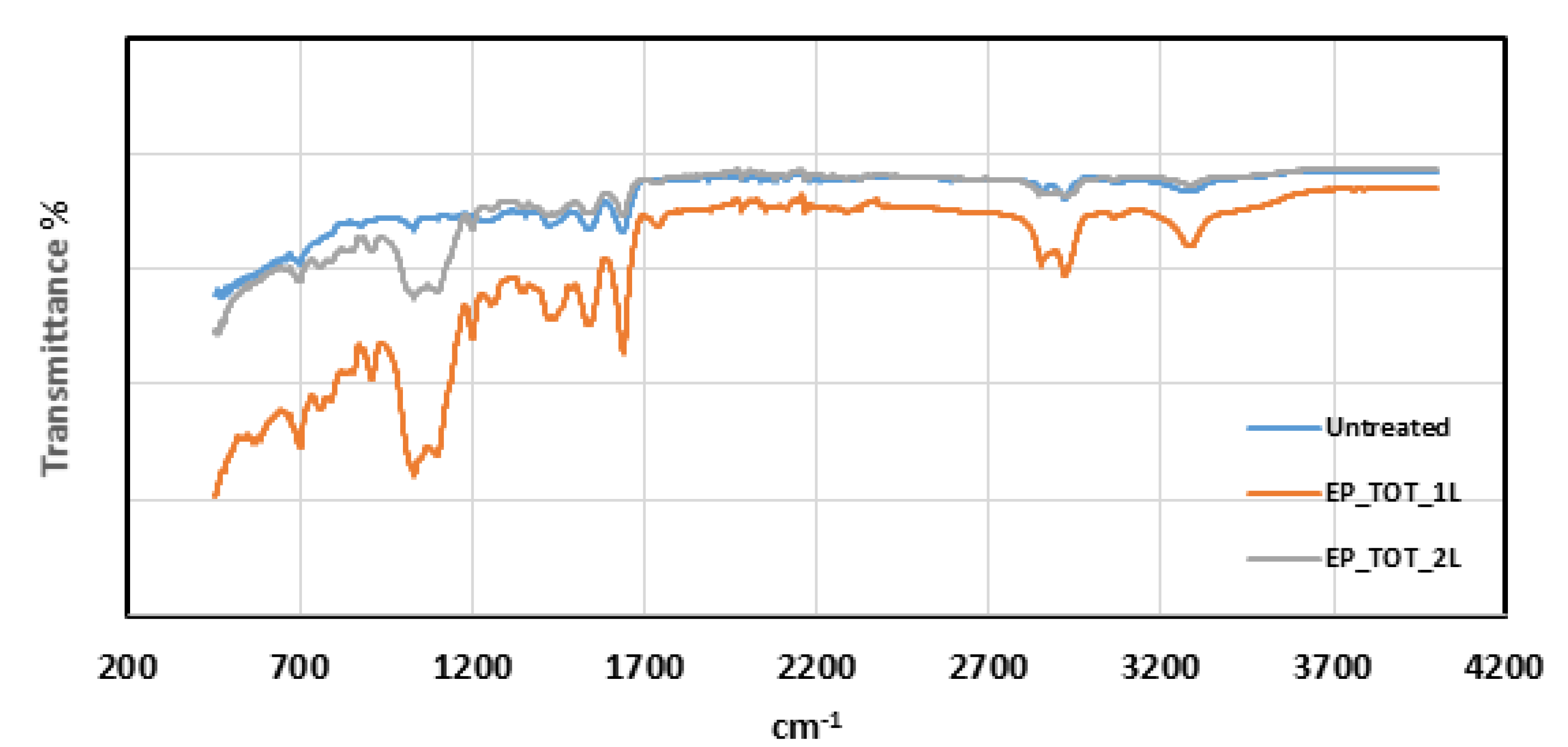
3.1. PA12-CR Surface Treatments

FTIR analysis was carried out on PA12-CR substrate surfaces in order to verify the effectiveness of silane treatments. Amino-based silane, similarly to epoxy-based silane, has CH2 and CH3 bonds identified by peaks of wavelength between 2850 and 2920 cm1, which are also present, however, in the thermoplastic substrate. For this reason, it is possible to verify the presence of the silane through the Si-O bond, characterized by the peaks between 1000 and 1100 cm1. In Figure 4 and Figure 5, it is possible to observe the difference between the spectra of the treated and untreated PA12-CR substrates.
For both silanes, the presence of the Si-O bond in comparison to the reference is noted. Moreover, for the amino-based silane, a variation of the curvature of the range between 2300 and 3700 cm1 can be observed, which identifies the vibration of the amino group of the silane. For the epoxy-based silane, there is a peak at the wavelength 1740 cm1, characteristic of the double bond C=O, representative of the epoxy ring.
The effect of the silane coupling agents is further evidenced by the results of the contact angle measurements (Figure 6) which show that the surface treated with epoxy-based silane has a better wettability (i.e., the lowest contact angle) than the surfaces of both untreated and amino-treated substrates. Moreover, the lower standard deviation evidenced for both treated surfaces shows that the silane treatment is characterized by high repeatability.

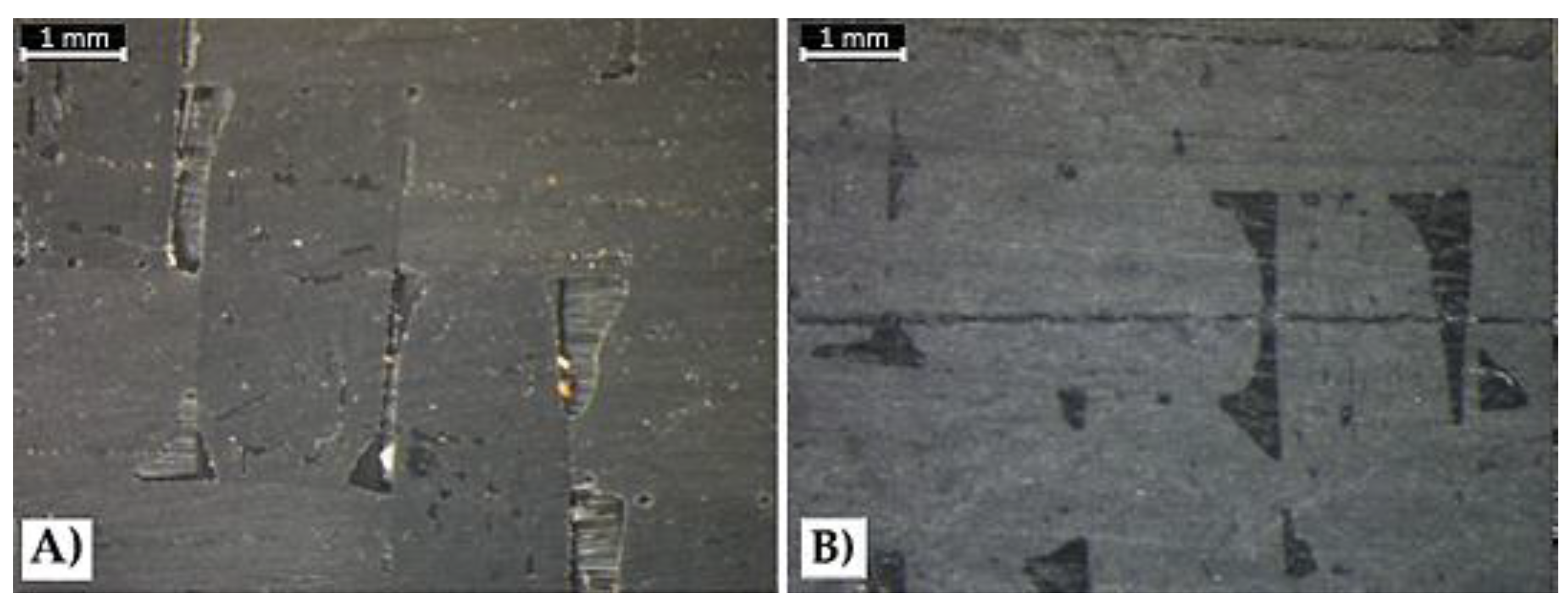
3.2. Analysis of the Double Cantilever Beam Test

The results of the DCB tests are shown in Figure 7.
The use of silane coupling agents evidenced that the ammine-based silane (AM) treatment provides a slight improvement in the case of 1 layer and Total Cure (47.7% on GIC init and 18.4% on GIC prop), while in all the other cases it leads a significant decrease of the adhesion. This behavior can be due to the insufficient conditions for reaction between AM silane and epoxy in the case of partial cure (i.e., 80 °C for 10 min before the hand lay-up phase of CFRP substrate)
On the contrary, the treatment with epoxy-based silane (EP) leads to significantly better results. In particular, the highest increase was recorded for EP_P_1L treatment, which allows to achieve an increase of 288.6% and 202.2% on GIC init and GIC prop, respectively. These results can be due to the high reactivity between the epoxy groups of the EP coupling agent and the amine groups of the epoxy resin [27].
The results also show that in the case of “2 Layers” deposition method, an adhesion reduction for both the silane coupling agents was found. This may be due to the fact that, by applying a second layer, the total thickness of the silane coating increases, which leads to a worsening of the joint mechanical properties caused by the cohesive breakage between the two layers of silane. Similar results were obtained by Hoikkanen et al. [28] who evidenced that in thermoplastic urethane–stainless steel hybrids structures the thickness of the silane coating leads to a decrease in the mechanical strength due to the failure within the silane layer. Hence, it is reasonable to assert that the deposition of a single layer is adequate to create a homogeneous coating layer.
The optical microscope observations of the fracture surfaces of untreated specimen (Figure 8) evidence that the resin is almost entirely on the CFRP surface with only small traces visible on the PA12-CR surface. This experimental result evidences that this specimen failed by adhesive mechanism, due to the low compatibility between the thermoplastic based composite and the epoxy resin. On the contrary, Figure 9 shows that the treatment with epoxy-based silane agent leads to a partial cohesive failure mode of the EP_P_1L specimen—that is, presence of a greater amount of resin on the PA12-CR substrate. This confirms the improved compatibility between epoxy resin and thermoplastic substrate that determines the significant increment of the adhesion between CFRP and PA12-CR substrates.

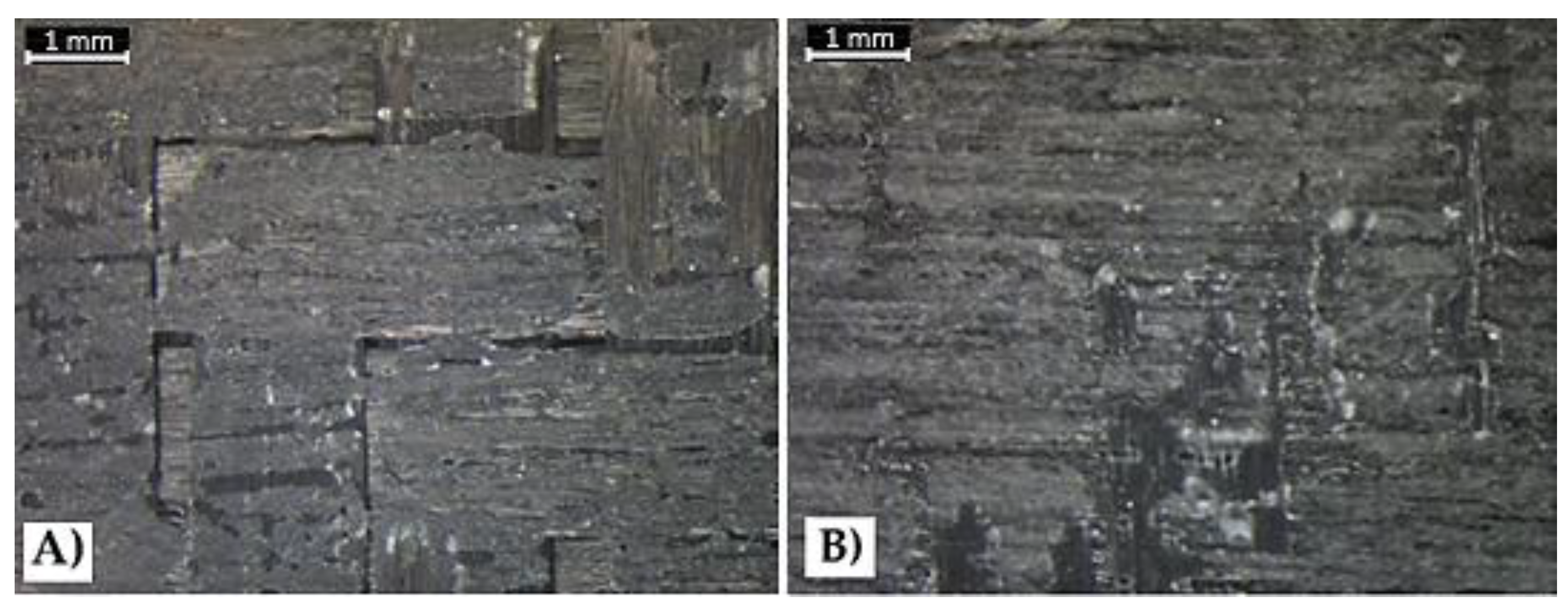
3.3. Mechanical Analysis of the Sandwich Structure

As already stated, from the experiment results it was noticed that the treatment with epoxy-based silane coupling agent showed the best effect on the adhesion between PA12-CR and CFRP substrates. To confirm this experimental evidence, the quasi-static flexural response of typical sandwich structures, used by OCORE company as bearing structure of a boat, was evaluated.
As can be seen from the stress-strain trends shown in Figure 10, the treatment with epoxy-based silane coupling agent (EP_P_1L) led to an increase of both the flexural strength σmax (i.e., 5%) and the equivalent flexural modulus Ef (i.e., 19.2%) of the sandwich structure, compared to untreated samples (UT). In addition, the treated structure evidences a partial recovery of its load capacity, due to the better adhesion between CFRP skin and printed PA12-CR core, up to 15 MPa. These experimental evidences confirm the beneficial effect of this treatment on the adhesion between PA12-CR core and CFRP skin of the sandwich structure. The results are summarized in Table 6.
Figure 11 shows that epoxy-based silane treatment leads to a modification of the failure mechanism.
The untreated sample, due to the poor adhesion between CFRP and PA12-CR substrates, experienced skin-core delamination immediately after the fracture of the printed substrate (Figure 11a). On the contrary, EP_P_1L treated samples, having an improved skin-core adhesion, experienced a pure CFRP skin tensile failure (Figure 11b).

4. Conclusions

The present paper aims to present one of the possibilities of how the adhesive properties between thermoplastic (i.e., Polyamide 12) and thermoset (i.e., epoxy) based composites, both reinforced with carbon fibers, can be improved. To this scope, two different silane coupling agents, (3-Aminopropyl)trimethoxysilane (AM) and (3-Glycidyloxypropyl)trimethoxysilane (EP), were applied, through the spray deposition method, on the polyamide 12 based substrate to create a reactive layer between the adherents. Furthermore, two different deposition methods that is, 1 Layer and 2 Layers as well as two coupling agents curing conditions namely Total and Partial Cure were also performed. Through tests of Contact Angle, Fourier Transform Infrared spectroscopy (FTIR), Mode I delamination tests (DCB) and three-point bending tests has been verified that:
  • The epoxy-based silane (EP) allows to obtain better adhesion improvement in comparison to amine-based silane (AM). In particular, (3-Glycidyloxypropyl)trimethoxysilane (EP) leads to improvements, in comparison to the reference sample, of about 288% and 197% for the GIC init and GIC prop, respectively;
  • The application of the second layer of silane coupling agent is not effective for improving the adhesion. The deposition of a single layer allows to create a homogeneous coating layer;
  • The Partial Cure has beneficial effect on the adhesion only in the case of epoxy-based silane, whereas it is not useful for amine-based silane, due to the insufficient conditions for reaction between AM silane and epoxy in this curing conditions (i.e., 80 °C for 10 min before the hand lay-up phase of CFRP substrate);
  • The application of the epoxy-based silane treatment led to an improvement of the adhesion between CFRP skin and printed PA12-CR core, thus leading to the improvement of the overall flexural response of the sandwich structures (i.e., +5% and +20% in the flexural strength and in the equivalent flexural modulus, respectively);
  • The enhanced adhesive properties lead to an improvement of the skin-core adhesion, thus resulting in the change of the failure mode from delamination between PA12-CR substrate and CFRP to tensile failure of the CFRP skin.

Author Contributions

Conceptualization, V.F. and A.V.; methodology, V.F. and A.V.; validation, V.F.; formal analysis, A.V.; investigation, V.O., C.S. and D.B.; data curation, V.O., C.S. and D.B.; writing—original draft preparation, V.O.; writing—review and editing, C.S., D.B. and V.F.; supervision, A.V. All authors have read and agreed to the published version of the manuscript.

Funding

This research received no external funding.

Acknowledgments

Authors would thank OCORE s.r.l., for providing thermoplastic based reinforced composites and carbon fabrics.

Conflicts of Interest

The authors declare no conflict of interest.

References

  1. Dau, J.; Lauter, C.; Damerow, U.; Homberg, W.; Tröster, T. Multi-material systems for tailored automotive structural components. In ICCM International Conferences on Composite Materials, 2011. Available online: https://www.iccm-central.org/Proceedings/ICCM18proceedings/data/2.%20Oral%20Presentation/Aug24(Wednesday)/W23%20Processing%20and%20Manufacturing%20Technologies/W23-3-IF1880.pdf (accessed on 27 May 2020).
  2. Zhang, J.; de Souza, M.; Creighton, C.; Varley, R.J. New approaches to bonding thermoplastic and thermoset polymer composites. Compos. Part A Appl. Sci. Manuf. 2020, 133, 105870. [Google Scholar] [CrossRef]
  3. Abbas, M.K.G.; Sakundarini, N.; Kong, I. Optimal Selection for Dissimilar Materials using Adhesive Bonding and Mechanical Joining. In Proceeding of the 1st International Postgraduate Conference on Mechanical Engineering (IPCME2018); IOP Publishing Ltd.: Pahang, Malaysia, 2018. [Google Scholar]
  4. Lee, S.W.; Chang, S.H. Experimental investigation of pull-through force of wing-type fastening inserts co-cured in long fiber prepreg sheet (LFPS). Compos. Struct. 2018, 206, 978–986. [Google Scholar] [CrossRef]
  5. Abouhamzeh, M.; Sinke, J. Effects of fusion bonding on the thermoset composite. Compos. Part A Appl. Sci. Manuf. 2019, 118, 142–149. [Google Scholar] [CrossRef]
  6. Ageorges, C.; Ye, L.; Hou, M. Advances in fusion bonding techniques for joining thermoplastic matrix composites: A review. Compos. Part A Appl. Sci. Manuf. 2001, 32, 839–857. [Google Scholar] [CrossRef]
  7. Encinas, N. Surface modification of aircraft used composites for adhesive bonding. Int. J. Adhes. Adhes. 2014, 50, 157–163. [Google Scholar] [CrossRef]
  8. Alamir, M.; Alonayni, A.; Asmatulu, E.; Paranjpe, N.; Rahman, M.M.; Asmatulu, R. Strength and failure analysis of composite-to-composite adhesive bonds with different surface treatments. Proc. SPIE 2018, 10596, 105961K. [Google Scholar]
  9. Tornow, C. Quality assurance concepts for adhesive bonding of composite aircraft structures-characterisation of adherent surfaces by extended NDT. J. Adhes. Sci. Technol. 2014, 29, 2281–2294. [Google Scholar] [CrossRef]
  10. Banea, M.D.; da Silva, L.F.M. Adhesively bonded joints in composite materials: An overview. Proc. IMechE art L J. Mat. 2009, 223, 1–18. [Google Scholar] [CrossRef]
  11. Baldan, A. Adhesively-bonded joints and repairs in metallic alloys, polymers and composite materials: Adhesives, adhesion theories and surface pretreatment. J. Mater. Sci. 2004, 39, 1–49. [Google Scholar] [CrossRef]
  12. Don, R.C.; Gillespie, J.W., Jr.; McKnight, S.H. Bonding techniques for high performance thermoplastic compositions. 1997. Available online: https://patents.google.com/patent/US5643390A/en (accessed on 27 May 2020).
  13. Williams, T.S.; Yu, H.; Hicks, R.F. Atmospheric pressure plasma activation of polymers and composites for adhesive bonding: A critical review. Rev. Adhes. Adhes. 2013, 1, 46–87. [Google Scholar] [CrossRef]
  14. Urbaniak-Domagala, W. Pretreatment of polypropylene films for the creation of thin polymer layers, part 1: The use of chemical, electrochemical, and UV methods. J. Appl. Polym. Sci. 2011, 122, 2071–2080. [Google Scholar] [CrossRef]
  15. Williams, D.F.; Abel, M.L.; Grant, E.; Hrachova, J.; Watts, J.F. Flame treatment of polypropylene: A study by electron and ion spectroscopies. Int. J. Adhes. Adhes. 2015, 63, 26–33. [Google Scholar] [CrossRef] [Green Version]
  16. Rider, A.N.; Arnott, D.R. Boiling water and silane pre-treatment of aluminum alloys for durable adhesive bonding. Int. J. Adhes. Adhes. 2000, 20, 209–220. [Google Scholar] [CrossRef]
  17. Wu, H.F.; Dwight, D.W.; Huff, N.T. Effects of silane coupling agents on the interphase and performance of glass-fiber-reinforced polymer composites. Compos. Sci. Technol. 1997, 57, 975–983. [Google Scholar] [CrossRef]
  18. Park, J.M.; Subramanian, R.V.; Bayoumi, A.E. Interfacial shear strength and durability improvement by silanes in single-filament composite specimens of basalt fiber in brittle phenolic and isocyanate resins. J. Adhes. Sci. Technol. 1994. [Google Scholar] [CrossRef]
  19. Plueddemann, E.P. Silane Coupling Agents, 2nd ed.; Springer Nature: London, UK, 1991; pp. 1–29. [Google Scholar]
  20. Zhu, L. Effect of absorbed moisture on the atmospheric plasma etching of polyamide fibers. Surf. Coatings Technol. 2008, 202, 1966–1974. [Google Scholar] [CrossRef]
  21. Karsli, N.G.; Aytac, A. Tensile and thermomechanical properties of short carbon fiber reinforced polyamide 6 composites. Compos. Part B Eng. 2013, 51, 270–275. [Google Scholar] [CrossRef]
  22. Calabrese, L.; Bonaccorsi, L.; Caprì, A.; Proverbio, E. Effect of silane matrix composition on performances of zeolite composite coatings. Prog. Org. Coatings 2016, 101, 100–110. [Google Scholar] [CrossRef]
  23. Scalici, T.; Pitarresi, G.; Badagliacco, D.; Fiore, V.; Valenza, A. Mechanical properties of basalt fiber reinforced composites manufactured with different vacuum assisted impregnation techniques. Compos. Part B Eng. 2016, 104, 35–43. [Google Scholar] [CrossRef]
  24. ASTM D5528-01. Standard test method for mode I interlaminar fracture toughness of unidirectional fiber-reinforced polymer matrix composites. Am. Stand. Test. Methods 2014, 3, 1–12. [Google Scholar]
  25. Standard Test Method for Flexural Properties of Sandwich Constructions: ASTM C 393; ASTM International: West Conshohocken, PA, USA, 2000.
  26. di Bella, G.; Calabrese, L.; Borsellino, C. Mechanical characterisation of a glass/polyester sandwich structure for marine applications. Mater. Des. 2012, 42, 486–494. [Google Scholar] [CrossRef]
  27. España, J.M.; Samper, M.D.; Fages, E.; Sanchez-Nacher, L.; Balart, R. Investigation of the Effect of Different Silane Coupling Agents on Mechanical Performance of Basalt Fiber Composite Laminates with Biobased Epoxy Matrices J.M. Polym. Compos. 2013, 34, 376–381. [Google Scholar] [CrossRef]
  28. Hoikkanen, M.; Honkanen, M.; Vippola, M.; Lepistö, T.; Vuorinen, J. Effect of silane treatment parameters on the silane layer formation and bonding to thermoplastic urethane. Prog. Org. Coatings 2011, 72, 716–723. [Google Scholar] [CrossRef]
Figure 1. Typical dimensions and set-up of a Mode I delamination test (DCB) specimen [24].
Fibers 08 00048 g001
Figure 2. Visual analysis of the crack propagation.
Fibers 08 00048 g002
Figure 3. Sandwich specimen for three-point bending test.
Fibers 08 00048 g003
Figure 4. Fourier transform infrared (FTIR) on untreated and (3-Aminopropyl)trimetoxysilane (AM) treated PA12-CR substrates.
Fibers 08 00048 g004
Figure 5. FTIR on untreated and (3-Glycidyloxypropyl)trimethoxysilane (EP) treated PA12-CR substrates.
Fibers 08 00048 g005
Figure 6. Contact angle between epoxy resin and PA12-CR substrates.
Fibers 08 00048 g006
Figure 7. (a) GIC init and (b) GIC prop values obtained from DCB tests.
Fibers 08 00048 g007
Figure 8. Optical microscope observations of the fracture surfaces of (A) carbon fabric reinforced epoxy resin (CFRP) and (B) PA12-CR of untreated (UT) specimen after DCB test.
Fibers 08 00048 g008
Figure 9. Optical microscope observations of the fracture surfaces of (A) CFRP and (B) PA12-CR of EP_P_1L specimen after DCB test.
Fibers 08 00048 g009
Figure 10. Typical stress-strain flexural curves of UT and EP_P_1L sandwich structures.
Fibers 08 00048 g010
Figure 11. Failure modes of sandwiches: (a) delamination failure of UT specimen and (b) tensile failure of EP_P_1L specimen.
Fibers 08 00048 g011
Table 1. Main mechanical properties of polyamide 12 reinforced with carbon microfibers (PA12-CR).
Mechanical Properties at 23 °C/50% RHNormativeValue
Tensile StrengthISO 527170 MPa
Elongation at breakISO 5272%
Modulus of ElasticityISO 52715 GPa
Charpy Impact StrengthISO 17947 KJ/m2
Table 2. Details of the silane coupling agents.
(3-Aminopropyl)trimethoxysilane (AM)(3-Glycidyloxypropyl)trimethoxysilane (EP)
Empirical FormulaC9H23NO3SIC9H20O5Si
Molecular Weight179.29236.34
Assay97%≥98%
Reactive GroupsAmine/MethoxyEpoxy/Methoxy
Density1.027 g/mL at 25 °C1.07 g/mL at 25 °C
Refractive Index1.4241.429
Table 3. Description of surface pre-treatment.
Type of Pre-TreatmentDescription of Pre-Treatment
RoughingPerformed by a belt sander equipped with 40, 80 and 120 grit
FinishingPerformed by a vibrating sander equipped with 150 grit
Cleaning and removing dustPerformed by a compressed air jet and absorbent paper
Table 4. Different coupling agents curing conditions, deposition and relative PA12-CR treatment description.
Type of CureType of DepositionPa12-Cr Treatment Description
Total Cure1. Layer(1)Spray deposition of the layer
(2)Cure for 3 h in oven at 80 °C
(3)Hand lay-up lamination
(4)Cure for 24 h in vacuum at room temperature
2 Layers(1)Spray deposition of the 1st layer
(2)Cure for 10 min in oven at 80 °C
(3)Spray deposition of the 2nd layer
(4)Cure for 3 h in oven at 80 °C
(5)Hand lay-up lamination
(6)Cure for 24 h in vacuum at room temperature
Partial Cure1 Layer(1)Spray deposition of the layer
(2)Cure for 10 min in oven at 80 °C
(3)Hand lay-up lamination
(4)Cure for 24 h in vacuum at room temperature
(5)Post-cure for 3 h in oven at 80 °C
2 Layers(1)Spray deposition of the 1st layer
(2)Cure for 10 min in oven at 80 °C
(3)Spray deposition of the 2nd layer
(4)Cure for 10 min in oven at 80 °C
(5)Hand lay-up lamination
(6)Cure for 24 h in vacuum at room temperature
(7)Post-cure for 3 h in oven at 80 °C
Table 5. Nomenclature and description of samples.
CodeDescription
UTUntreated
AM_T_1LAmino-based silane—Total Cure—1 Layer
AM_T_2LAmino-based silane—Total Cure—2 Layers
AM_P_1LAmino-based silane—Partial Cure—1 Layer
AM_P_2LAmino-based silane—Partial Cure—2 Layers
EP_T_1LEpoxy-based silane—Total Cure—1 Layer
EP_T_2LEpoxy-based silane—Total Cure—2 Layers
EP_P_1LEpoxy-based silane—Partial Cure—1 Layer
EP_P_2LEpoxy-based silane—Partial Cure—2 Layers
Table 6. Comparison between treated and untreated sandwich structures.
σmax [MPa]Ef [MPa]
AverageDev.St.AverageDev.St.
UT39.83.71198222.8
EP_P_1L41.82.31428146.6

