1. Introduction
At the present time, high bit rate networks are based not only on single-mode optical fibers. Nowadays, laser-excited optical signal transmission technique over large core silica optical fibers is widely applied in various applications. It should be noted that this technique, combined with special launching conditions, provides a few-mode regime. Here laser-excited optical emission is transferred over large core optical fiber by some limited number of guided modes, while under the multimode regime, transmitted optical signal contains almost all guided modes, satisfying cut-off conditions. In 1998 [
1,
2], IEEE 802.3z standard was ratified, which declared for the first time laser-based 1 Gbps data transmission over silica graded-index multimode optical fibers (MMFs) with conventional core diameters 62.5 μm and 50 μm (ANSI/TIA Cat. OM1 and OM2). As a result, this technique started to be widely used for short-range and in-premises multi-Gigabit networks, based on mentioned above MMFs with core/cladding diameter 62.5/125 and 50/125 μm [
1,
2,
3,
4,
5,
6]. Structural cable systems of data and computation centers and storage and local area networks became the main customers of described technique [
1,
2,
3,
4,
5,
6]. At the same time, leading worldwide optical fiber manufacturers started to develop and successfully implemented several generations of MMFs of Cat. OM2+…OM4 known as “LOMFs” (Laser-Optimized-Multimode-Fibers) with core diameter 50 μm, which were further ratified by IEEE for Gigabit and multi-Gigabit networks with laser-based transceivers and multimode fiber optic links, operating in a few-mode regime [
2,
3,
4,
6].
Today, laser-based data transmission starts to be in demand for on-board and industrial networks. Nowadays, such networks also require 1 Gbps and even more higher bit rates [
7,
8,
9]. Onboard and industrial cable systems operate in harsh environmental conditions: high-dense mounting space, vibrations, dust suspending in the air, etc., therefore, the greater fiber core diameter, the more total network reliability. From this point of view, silica optical fibers with extremely enlarged great core diameter have some advantages: (a) large core optical fiber provides immunity to bend loss (especially in comparison with standard single-mode optical fibers of ITU-T Rec. G.652) [
1,
3,
6,
7,
8,
9] while (b) fiber optic connections of this type MMFs are less insensitive to vibrations and (c) to contamination of fiber optic connector ferrule end; (d) silica core an silica cladding provide lower loss (more than 1 order) in comparison with polymer or plastic core/cladding optical fibers. Therefore, ratified MMFs with enlarged core diameter up to 100 μm (100/125 and 100/140) can be considered as the optimal solution for cable systems of described short-range networks. At the same time, the most of commercially available MMFs with 100-μm core diameter are targeted to low bit rate (10…100 Mbps) networks with fiber optic systems, based on multimode light emitting diodes (LEDs) transceivers, e.g., they are suitable only for multimode regime of data transmission. In the earlier on published works [
10,
11,
12], we presented an alternative fast and simple method for the design of special graded refractive index profile of large core silica LOMFs. Here, we demonstrated some results of profile optimization performed for 100-μm core LOMF by proposed solution. These samples of designed graded refractive index profiles were targeted on differential mode delay (DMD) decreasing for selected guided modes over the “O”-band under particular launching conditions. This work presents manufactured new type of silica LOMF 100/125—with extremely enlarged core diameter up to 100 μm and “typical” “telecommunication” cladding diameter 125 μm and low DMD, provided by earlier on developed samples of special optimized graded refractive index profiles [
10,
11,
12]. We demonstrate some results of tests, performed for manufactured pilot 520 m length of described LOMF 100/125, concerned with its geometry properties as well as key transmission parameters—attenuation and DMD map.
2. Laser Optimized Multimode Optical Fibers with 100-μm Core Diameter
Laser-excited optical pulse propagation over MMF with large core (in comparison with standard telecommunication single-mode optical fibers) differs from a multimode regime by the appearance of the DMD effect [
1,
2,
3,
4,
5,
6] due to here optical signal is transferred by not the almost all guided modes that satisfy to cut-off conditions but only the limited number of them. The main reason of DMD appearance is the launch of laser-excited optical emission with small spot size to MMF with large core diameter. This great distinction leads to the excitation of just a limited number of particular order modes differing by their delays, while during the propagation in MMF, the amplitudes of these selected mode components, containing in the optical signal, are non-equal. It is mainly defined by the launching conditions of the laser-excited optical signal into the optical fiber core end, by using the typical fiber optic adaptor with uncontrolled radial or angular misalignments, or by utilizing the special device like matching optical fiber or lens system, etc., providing centralized connection or vice versa, pre-set precision angular or radial misalignment. During laser-excited optical signal propagation over MMF, some new guided modes may be excited by mode mixing and power diffusion (e.g., mode coupling effects) occurring due to optical fiber irregularities and micro-/macro-bends. However their number is also limited, as well as their amplitudes also may be weak and neglected with normalized values to less 0.1. Therefore, at the transmitter end of the fiber optic link, the optical pulse contains several modes with non-equal amplitudes and differing mode delays (e.g., mode group velocities), while at the receiver end it comes with spread of both amplitudes and delays relative each other that causes to pulse splitting and may strongly distort it: from the initial typical quasi-Gaussian to inappropriate “glove” form at the receiver end. Moreover, for each particular “laser–MMF” couple DMD may strong differ from other. It depends on random factors of launching conditions and launching uncertainty provided by the variations of sources, connections, and fiber parameters. That is why DMD is a main issue for short-range multi-Gigabit optical networks based on MMFs.
Unlike known solutions (detailed overview is presented in the earlier on published papers [
10,
11,
12] and monograph [
13]), we proposed to take into account the following outlined factors during the design refractive index profile for LOMF with extremely large core diameter [
10,
11,
12]:
Real and approved commercially available LOMFs of Cat. OM2+...OM5 parameters (geometry, refractive index profile, etc.), taken from the measurement reports/data sheets/specifications, should be used initially, but neither parameters of model optical fibers with the ideal graded refractive index profiles described by just one or a set of simple power-law α-functions nor the first generation MMFs of Cat. OM1 and OM2, should be targeted to only multimode regime;
The development or modification of a fiber structure/refractive index profile during each step of optimization procedure has to be based on results of comparison between the desired DMD diagram and DMD diagram, obtained in the previous iteration;
The laser source type and its parameters—especially initial number and order of transverse modes containing in the laser-generated emission as well as the launching conditions—should be taken into account;
DMD should be decreased not only at particular wavelengths but over the desired spectral range (for example, conventional telecommunication “O”-band with a reference wavelength λ = 1300–1310 nm).
Proposed method for design of special graded refractive index profile, providing of selected guided mode delay equalization around some reference mode delay value
tREF, is described in details in the earlier on published papers [
10,
11,
12]. We consider typical silica optical fiber geometry containing fused silica core doped by Germanium and Fluorine bounded by single pure fused silica outer solid cladding. It satisfies weakly guiding optical waveguide approximation. Here, unlike to the most known solutions, we apply stratification method [
14] approach to describe complicated graded index refractive index profile. Therefore, in the core region, designed refractive index profile for large core LOMF with equalized selected mode delays is represented in the form of multilayered optical fiber. It contains finite set on
N layers, where refractive index value stays constant. Desired refractive index profile form should satisfy minimization of some objective function
F, which is described by the following proposed simple formula:
where
td(j) is desired value of delay for
j-th guided mode
LPlm(j) been computed at corresponding optimization step;
tREF is some reference value of mode delay, which is utilized for DMD diagram equalization;
M is the total number of selected guided modes transferring laser-excited optical signal with normalized amplitude not less than
Aj > 0.1 and core power (known also as optical confinement factor) not less than
. Objective function arguments are an array of local parameters
hk, completely describing optical fiber refractive index profile under the stratification method approach:
where
nk is refractive index of
k layer
(k = 0…N);
nmax is the maximal core refractive index;
nN is outer cladding refractive index.
During objective function (1) minimization, a direct problem of analysis of optical fiber with current refractive index profile should be solved at the each optimization iteration. For this purpose, we utilize earlier on developed modified [
15] Gaussian approximation [
16], extended for analysis and computation of arbitrary order guided mode transmission parameters in weakly guiding optical fibers with arbitrary axially symmetrical refractive index profile [
15,
17,
18] (EMGA—Extended Modified Gaussian Approximation), under the following corresponding modification for 100-μm core, which is described in detail in the publications mentioned above [
10,
11,
12].
In the first step, we utilized LOMF 50/125 refractive index profile, taken from measurement report and further scaled up to 100-μm core diameter, as the reference profile to define boundary values of the reference mode delay
tREF range by computing of selected guide mode DMD diagram. These measurements of refractive index profile mentioned above were performed by certified optical fiber analyzer for the sample of commercially available LOMF of Cat. OM2+/OM3 [
19]. By using EMGA, we performed analysis of the reference 100-μm core MMF over “O”-band, which included computation of mode field radius, propagation constant (with following test on satisfaction to cut-off condition) and optical confinement factor. According to computational results, the reference graded-index 100-μm core MMF supports propagation of 145 modes
LPlm (
l = 0...24;
m = 1…11) satisfying to the cut-off conditions with optical confinement factor more
Pco > 0.5. By taking into account described above features of laser-excited optical signal propagation over MMF in a few-mode regime, we do not need to equalize mode delays over all guided modes unlike to multimode regime. Here only guided modes
LPlm with normalized amplitudes more
Aj > 0.1 and optical confinement more
should be considered under particular launching conditions.
Therefore, during the next step, we proposed to consider centralized launching of the optical signal generated by conventional Fabry–Perot laser diode (LD) at the wavelength λ =1310 to the reference MMF core end via standard single mode optical fiber (ITU-T rec. G.652). Here, in the “worst case”, launched optical emission may contain two transversal modes
LP01 and
LP11 at the mentioned above wavelength. By using earlier on developed model for simulation of piece-wise regular multimode fiber optic link operating in a few-mode regime [
17], we performed computation of normalized amplitude distribution dynamics over all guided modes, supported by the reference MMF, under centralized launching of modes
LP01 and
LP11, and further mode power redistribution due to bends for several regular spans of piece-wise regular fiber optic link representation.
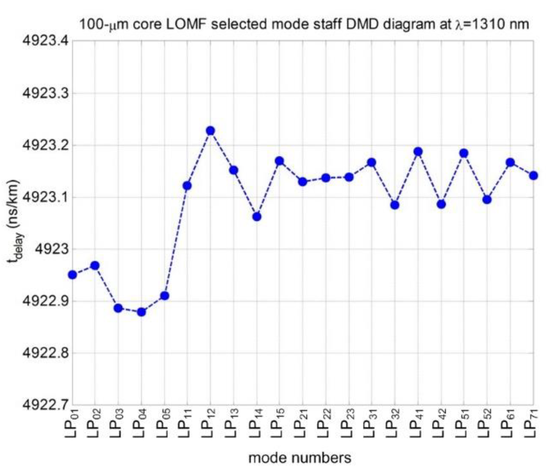
We noticed that only 21 guided modes LPlm (l = 0…7; m = 1…5) transfer the most part of optical signal during its propagation along the reference 100-μm core MMF, while normalized amplitudes of other components are less 0.1. Their delays vary from 4.922 up to 4.924 ns/km, that defines the boundaries of the range for the mode delay reference value tREF setting, while after some preliminary optimization attempts, boundary values for range of α-parameter of the first iteration graded profile were also evaluated: α = 1.75...2.15. We performed more 100 optimizations under various combinations between particular values of α-parameter and the reference mode delay tREF, taken from the described above ranges. As a result, we obtained a set of optimized refractive index profile samples providing DMD decreasing over all “O”-band from 5.0 up to 9.0 times in comparison with the reference 100-μm core MMF.
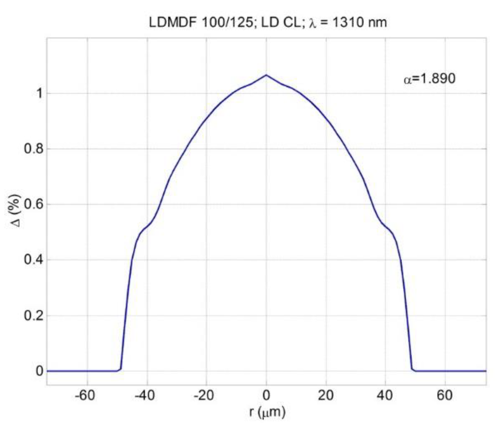
During the next step we selected the simplest profile form for the following implementation. It corresponds
tREF = 4923.08 ns/km and α = 1.890 combination, and it is represented in
Figure 1.
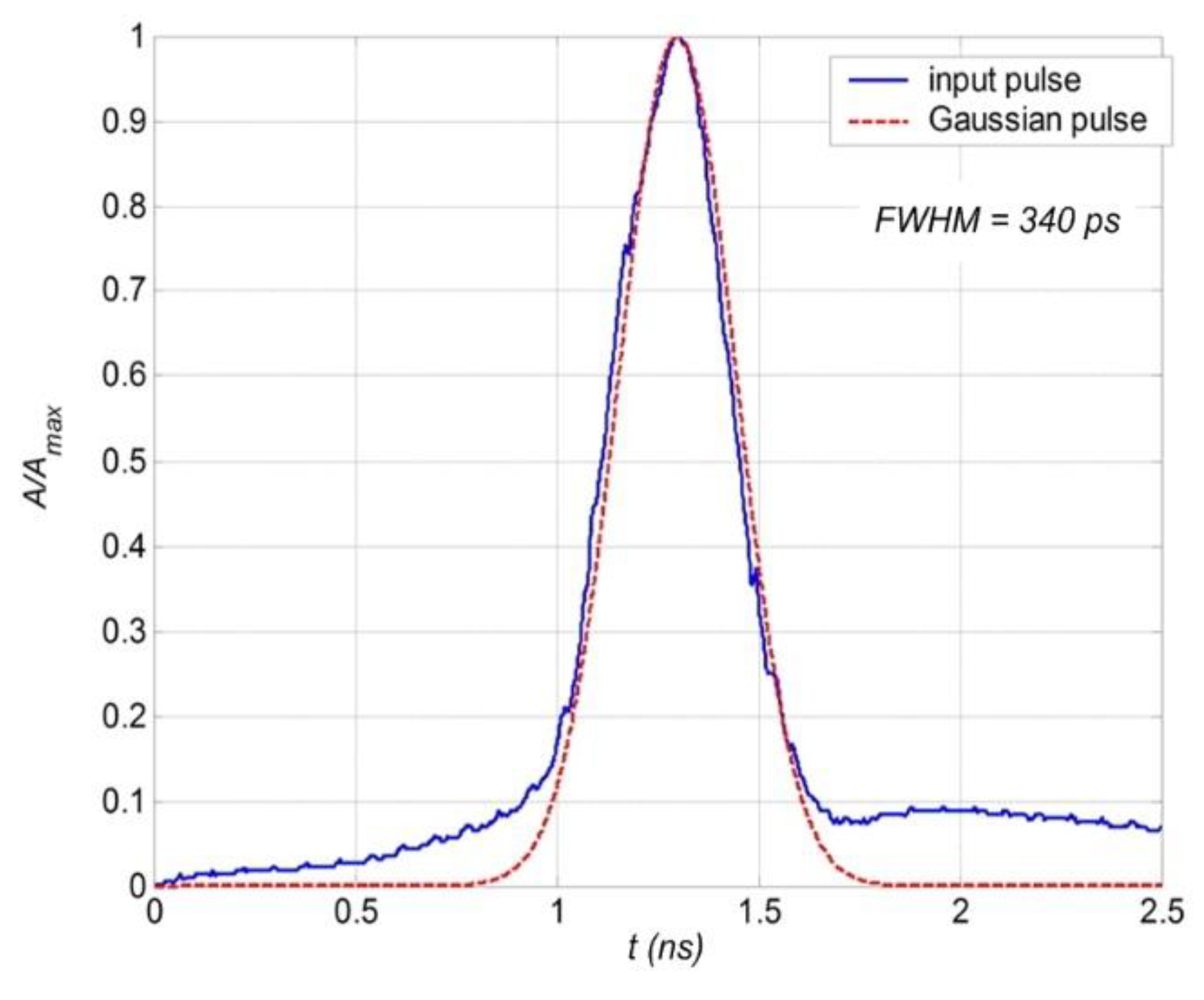
Computed DMD diagram of mentioned above 21 guided modes for the selected sample of LOMF is shown on
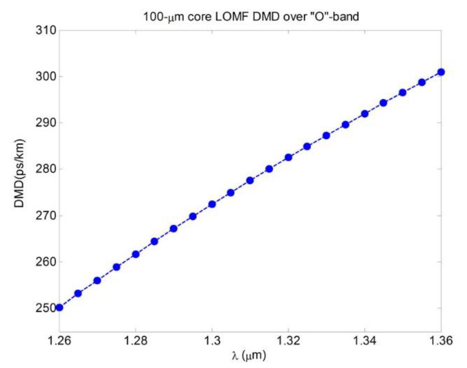
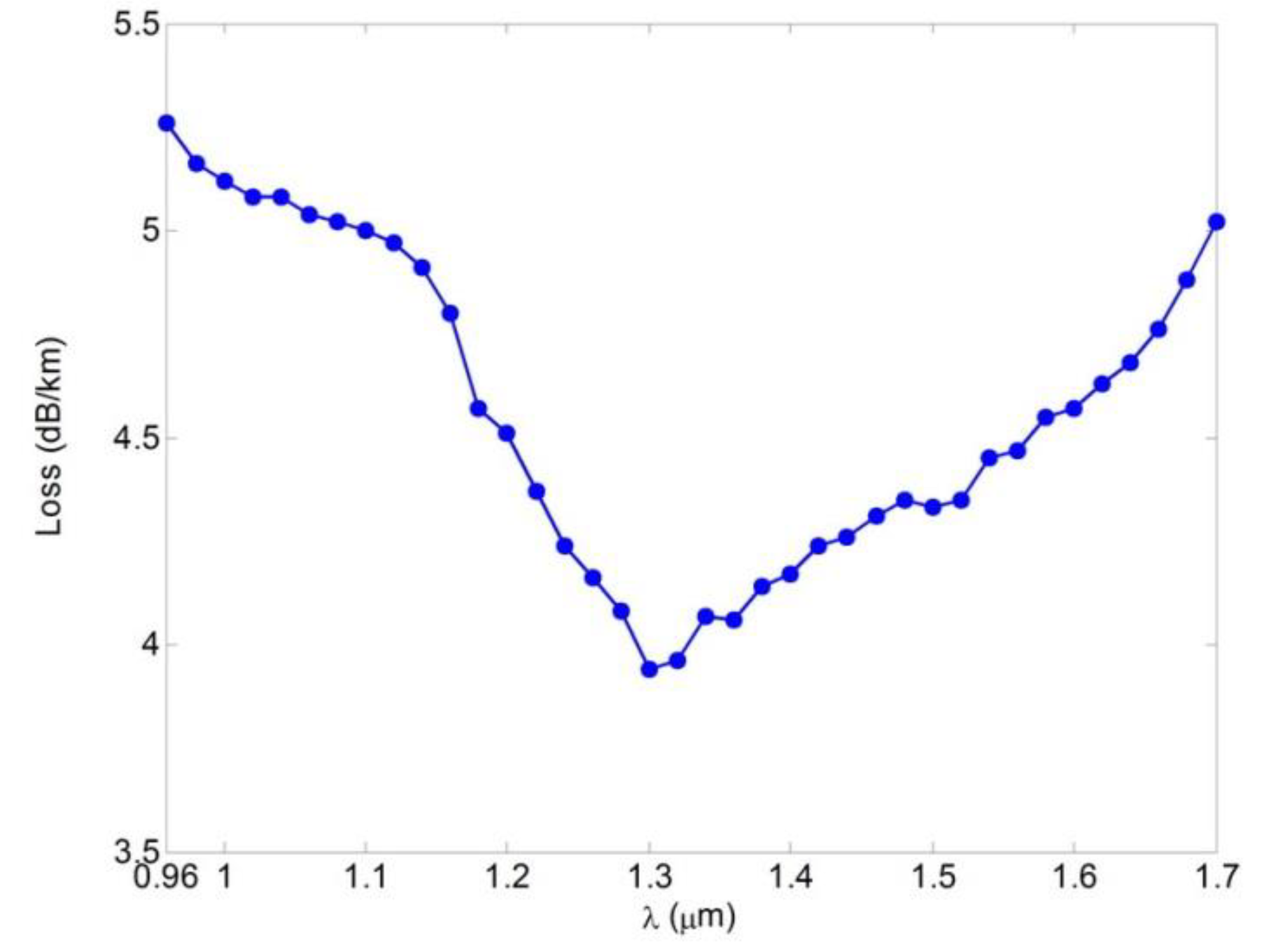
Figure 2, while theoretical spectral curve of DMD regarding to the fundamental mode
DMDLP01 (λ) calculated over “O”-band is represented on
Figure 3. According to computed results, we predict the worst case effective modal bandwidth at least 2500 MHz·km.
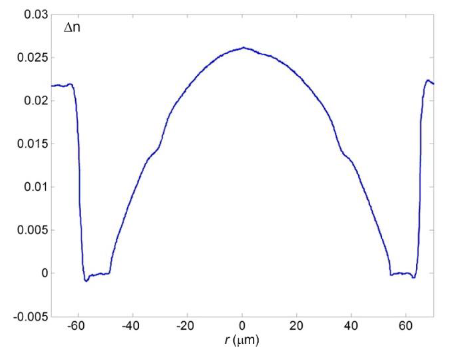
During the next step, optical fiber preform was manufactured by FCVD (Flame Chemical Vapor Deposition) technique with outer diameter 28.730 mm and “core” diameter 23.138 mm. Written refractive index profile of preform is shown on
Figure 4. Here “cladding” is pure silica, while desired graded refractive index profile in “core” region was formed by Ge/F dopants. Then, a pilot 520 m length of designed LOMF 100/125 was drawn. Refractive index profile, measured by optical fiber analyzer on the sample of drawn LOMF 100/125 is demonstrated on
Figure 5. Here, unwanted central dip was successfully collapsed during the drawing process and transformed to desired weak peak, while profile peculiarities in the periphery core region were also reconstructed almost according to optimized form.
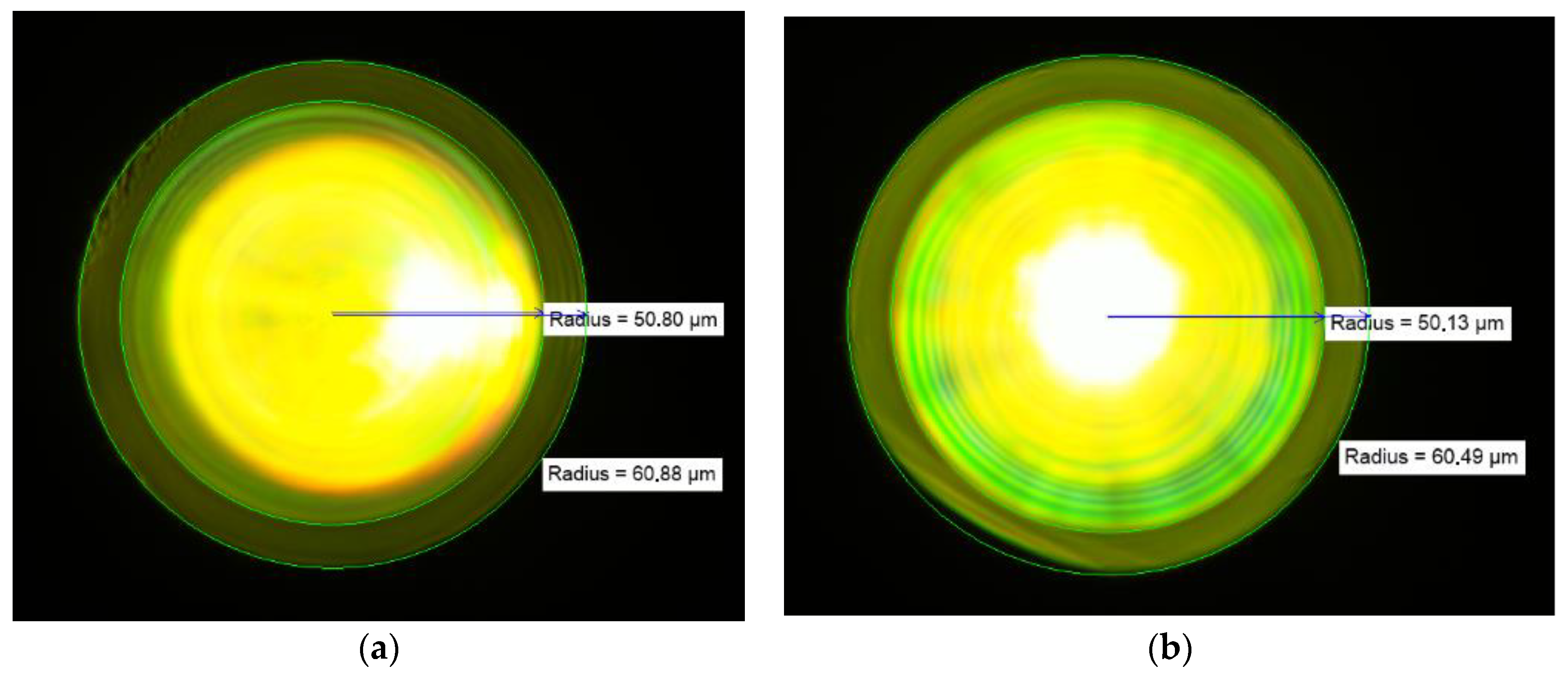
Results of measurements of manufactured LOMF 100/125 cladding to core diameter ratio (CCDR), performed at the beginning and the end of drawn 520 m length, are presented on
Figure 6a,b. Here CCDR at the start point is 60.88/50.68 = 1.198, while at the end it is 60.49/50.13 = 1.207.
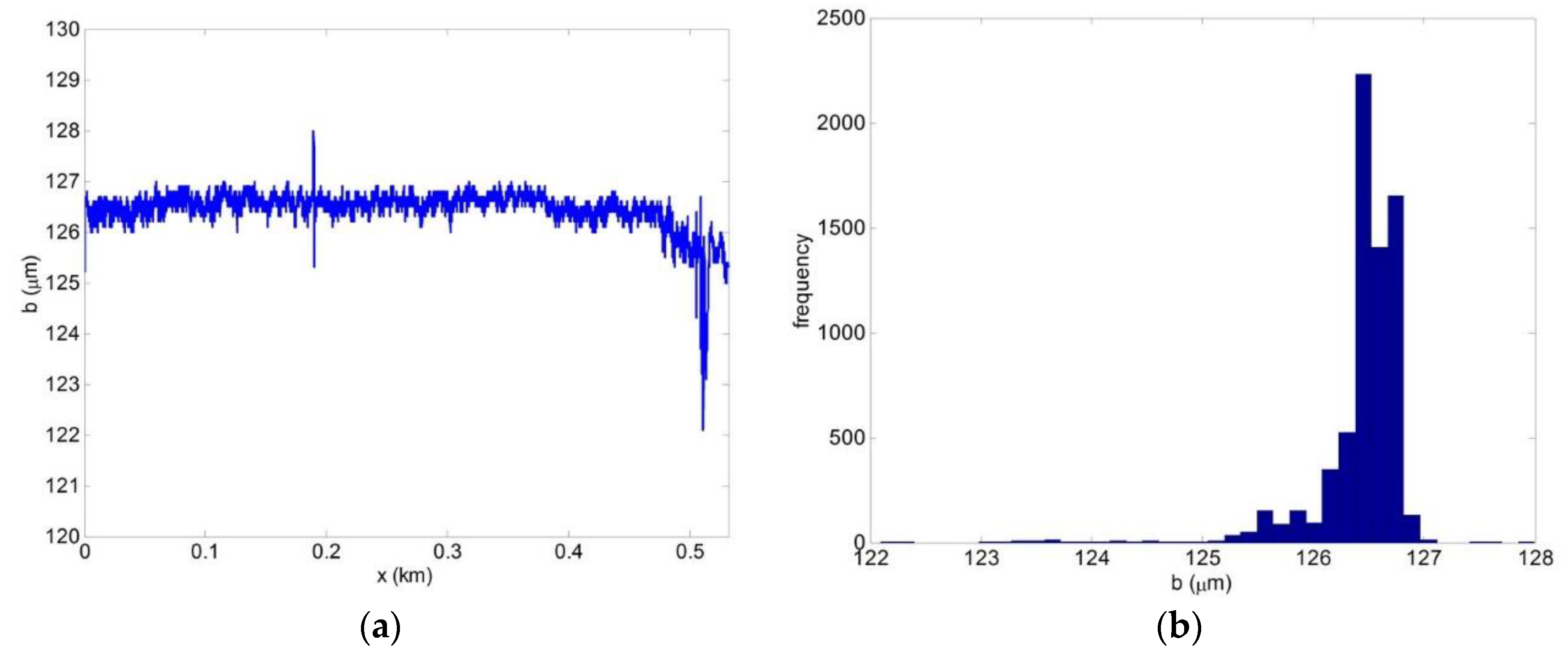
Report of outer cladding variation measurements, performed during optical fiber length drawing, and histogram of its statistic distribution are presented on
Figure 7a,b. Here maximal deviation of the reference diameter value 125 μm is not more 3.00 μm.
4. Bandwidth
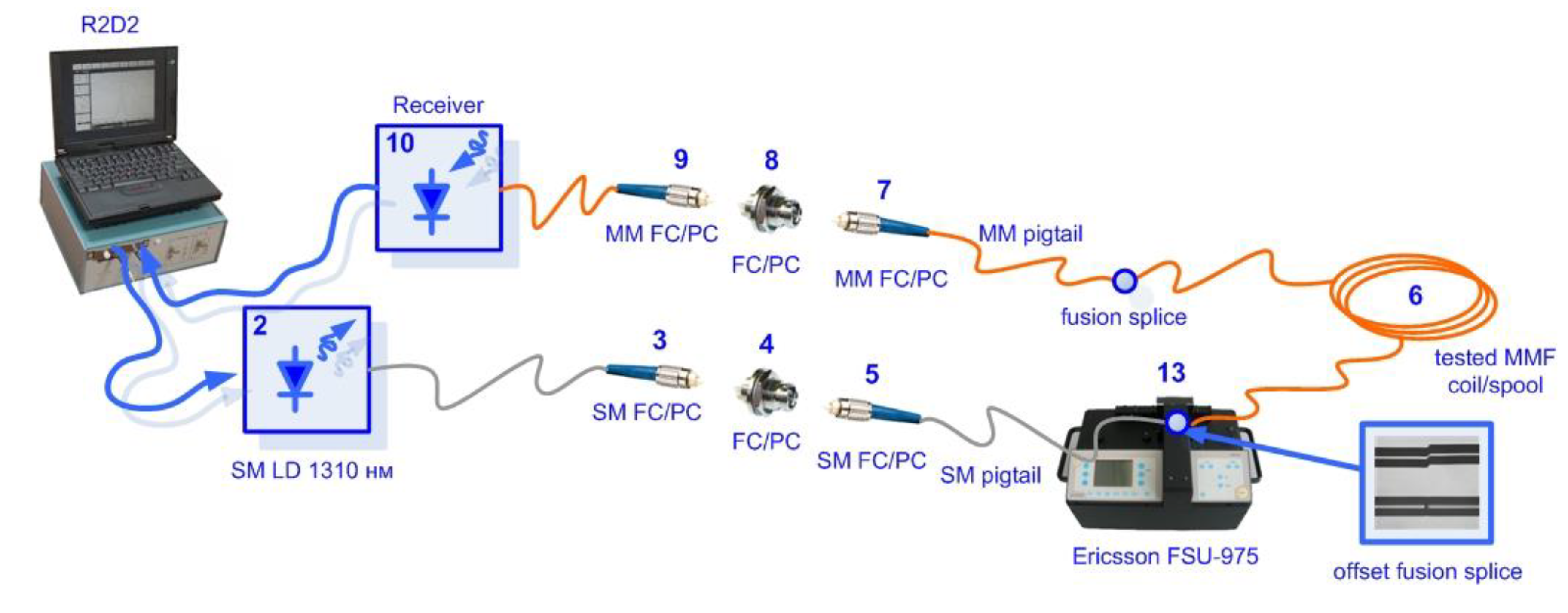
During the next step, we performed DMD map measurement of manufactured 520 m pilot length of LOMF 100/125 by DMD analyzer workstation lab kit R2D2 [
20,
21], according to ratified standards TIA-455-220-A/FOTP-220 and IEC 60793-2-10, concerned with laser-excited optical pulse response measurements at the tested MMF receiving end under precision offset launching conditions. Simplified block-scheme of the experimental setup for DMD map measurement under control of launching conditions is shown on
Figure 9; workstation and software R2D2 screenshot are shown on
Figure 10 and
Figure 11.
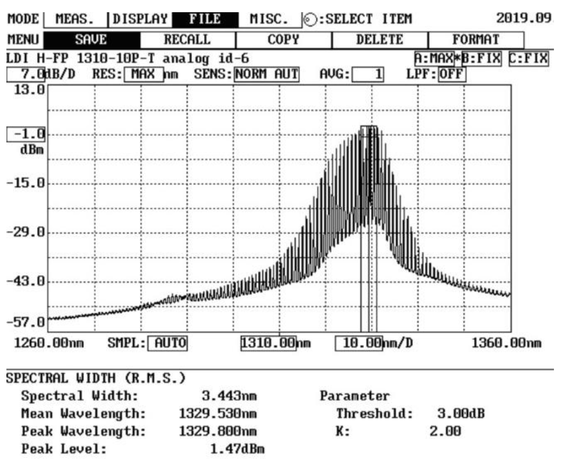
The Fabry–Perot LD “2” generates quasi-Gaussian optical pulse at wavelength λ = 1310 nm with width at a half maximum (FWHM) about 340 ps. It is pigtailed by standard single-mode (SM) optical fiber ITU-T Rec. G.652 terminated by FC/PC connector “3”. Emission from the LD output is launched to MMF via single-mode pigtail (ITU-T Rec. G.652) “5”, which is spliced with tested MMF under precision offset by fusion splicer via program “Attenuator”. Here parameter “Attenuation” is set to 0, “offset”—to particular value, and “ECF factor” (surface tension compensation factor) also is set to 0 to avoid deformations in the heat zone of the offset fusion splice. Measured spectrum of DMD analyzer laser source is shown on
Figure 12. Reference optical signal (measured via short SM patch-cord) with overlapped Gaussian pulse is represented on
Figure 13.
Results of DMD map measurement with 1.0 μm interval of the offset launching over range 0…25.0 μm are represented on
Figure 14. Here, optical pulse keeps its envelope without any DMD distortions over all the researched offset ranges up to 25 μm misalignment under corresponding spreading that also demonstrate potential survivability of developed LOMF 100/125 to the launching conditions.
Therefore, during the next stage, we performed estimation of pulse dispersion in relation to initial its FWHM 340 ps by the well-known method for signal with arbitrary form spreading estimation (for example, it is described in details in the textbook [
22]). Results of dispersion evaluation are shown on
Figure 15. The minimal dispersion (150...175 ps) corresponds not to only centralized and low offset launching conditions, but also, it is achieved under the great radial misalignment between cores of matching SM and tested LOMF 100/125 optical fibers with value up to 10 μm. We computed approximate acceptable values of dispersion for 1000Base-LX and 10GBase-LX specifications and 520 m MMF link by “the worst case” link model, developed by IEEE 802.3z Task Force for the first time, declared and ratified ability of laser based data transmission over MMFs with 1 Gbps bit rate [
23,
24], by taking into account typical transceiver power budget parameters [
25]. As a result, the maximal measured pulse dispersion corresponds to offset 25 μm, and it is not more than 300 ps, while estimated acceptable values for 1000Base-LX and 10GBase-LX specifications for 520 m MMF link are 874.5 ps and 87.1 ps, respectively, which demonstrates good bandwidth potentiality of proposed designed and manufactured LOMF 100/125 for applications on the short range onboard and industrial multi-Gigabit network cable systems.
Finally, during the next stage, we directly measured bit error rate (BER) of IEEE 802.3z 1000Base-LX data transmission channel over 520 m link with presented LOMF 100/125 by certified interface analyzer. For this purpose, we terminated both ends of LOMF 100/125 by conventional FC fiber optic connector with an adhesive and polishing ferrules and utilized MMF 50/125 LC patch-cords via fiber optic adapter FC/LC for connection to analyzer transceivers. During typical 70 h measurements, no errors were detected, and BER stayed zero (BER = 0). Therefore, first time we demonstrated guaranteed successful laser-based 1 Gbps bit rate data transmission over 520 m MMF link with proposed LOMF 100/125 under 1000Base-LX interface without any special launching conditions.

 ,
, 


