Article

Ballistic Performance of Lightweight Armor Aramid Fabric with Different Bounding Technologies

by
István Péter Kondor
*,
János Líska
and
Zsolt Ferenc Kovács
Department of Innovative Vehicles and Materials, GAMF Faculty of Mechanical Engineering and Computer Science, John von Neumann University, H-6000 Kecskemét, Hungary
*
Author to whom correspondence should be addressed.
Fibers 2025, 13(8), 106; https://doi.org/10.3390/fib13080106
Submission received: 6 June 2025 / Revised: 21 July 2025 / Accepted: 28 July 2025 / Published: 5 August 2025

Abstract

Highlights

What are the main findings?
  • This study investigates the ballistic performance of Kevlar fabric laminated with epoxy and polyurethane binders using simulations and laboratory testing.
  • Polyurethane-bonded composites demonstrated superior multi-hit resistance and energy absorption compared to epoxy and unbonded configurations.
What is the implication of the main finding?
  • ANSYS Explicit Dynamics simulations correlated well with experimental results, validating the numerical model for high-strain-rate impact.
  • The findings support polyurethane as the optimal binder for lightweight, flexible ballistic armor in military and civilian applications.

Abstract

The aim of this research was to develop a lightweight armor that could be used in bulletproof vests or vehicle protection, offering an alternative to the disadvantageous properties of high-strength steel plates. Specifically, the study focused on investigating the properties of different binders to identify the most suitable one for further development. The bulletproof characteristics of Kevlar (aramid) fiber fabric (200 g/m2, plain weave, CT709) were examined using both the Ansys simulation environment and ballistic laboratory testing. In the experiments, three different layer configurations were tested on 300 × 300 mm specimens, each consisting of 20 layers of Kevlar. The layers were arranged as follows: dry lamination for the first specimen, epoxy binder for the second, and polyurethane binder for the third. Laboratory tests were conducted using 9 mm Parabellum bullets, in accordance with the parameters defined in the MSZ K 1114-1:1999 standard. Both the ballistic and simulation tests indicated that the Kevlar laminated with polyurethane resin demonstrated the most promising performance and is suitable for further development.

1. Introduction

In the face of increasing global threats such as terrorism and armed conflict, the demand for efficient and lightweight body armor has become critical for military and law enforcement personnel. Body armor components—such as vests, helmets, shields, and limb guards—must balance high protection levels with mobility and user comfort. The development of fibrous materials has opened new possibilities in this domain, allowing for the creation of high-strength, lightweight ballistic composites using materials such as aramid, high-tenacity nylon, and ultra-high-molecular-weight polyethylene (UHMWPE) fabrics [1]. The ballistic performance of body armor depends on various factors, including the type and construction of the textile layers (e.g., woven, non-woven, biaxial, triaxial, and knitted), the areal density, thread count, and the number and arrangement of layers [2,3,4]. Additionally, modifications to the interlayer interfaces—such as the use of hybrid constructions, stitching patterns (e.g., diamond or spot stitching), or chemical bonding—can influence backface deformation and energy absorption capacity [5,6]. In recent years, increased attention has been paid to composite laminates reinforced with woven fabrics under dynamic loading. For example, Zhang et al. modeled the ballistic impact response of nylon-based composites [7], while Vescovini et al. presents an experimental study on the low-velocity impact behavior of glass, Kevlar, and hybrid fiber-reinforced composites using an elastomeric polyurethane matrix [8]. Ghosh et al. [9] contributed to this field by analyzing the strain-rate-dependent behavior of metals (e.g., 4340 steel and Al 7075-T6), which are often used as comparative baselines for advanced composite materials in armor systems. Additionally, Rahman et al. explored the high-velocity impact response of polymers such as PMMA [10], providing insights into the behavior of alternative lightweight substrates. Bonding technologies also play a pivotal role in shaping the mechanical and ballistic response of multilayer armor systems. Laminating woven aramid layers with polymeric binders such as epoxy or polyurethane can enhance structural integrity and projectile resistance. However, the influence of binder type, distribution uniformity, and interfacial adhesion remains a key challenge in optimizing performance [11]. Therefore, the objective of this research is to evaluate the impact resistance of Kevlar (aramid) fabric composites laminated using different binders—specifically epoxy and polyurethane—and to determine the most suitable bonding method for future armor development. Both numerical simulations and ballistic laboratory tests were employed to assess the protective capabilities of these laminated structures under 9 mm Parabellum full metal jacket (FMJ) projectile impact.
The authors in this study performed the first systematic comparison of polyurethane and epoxy in Kevlar laminates, demonstrating the superior stability of polyurethane against multiple impacts.

2. Numerical Analysis of the of the 9 mm Parabellum Bullet Projectile Penetration

2.1. Enhanced Description and Validation

2.1.1. Material Model Parameters and Source Justification

The Johnson–Cook (J–C) plasticity and failure models were implemented to simulate the high-strain-rate impact behavior of the tested materials. Table 1 provides the explicit values for the J–C model parameters used in the ANSYS Explicit Dynamics environment:
Where necessary, Johnson–Cook parameters were sourced from the recent peer-reviewed literature. The epoxy and polyurethane binder models were derived from high-strain-rate test data and calibrated using Split–Hopkinson Pressure Bar (SHPB) results, as presented Yuan et al. [8].

2.1.2. Model Validation with Experimental Data

To enhance model credibility, simulation results (penetration depth, bullet deformation, and residual velocity) were directly compared with experimental ballistic tests using 9 mm Parabellum rounds. The penetration depth deviation between simulations and experiments remained within ±8%, which is acceptable for dynamic FEA. Sources of discrepancy include the following:
  • Mesh density in high-deformation zones (mesh sensitivity tested at 0.5 mm and 1 mm element size).
  • Idealized contact definitions (frictionless penalty contacts were used).
  • Homogeneous material assumption, neglecting micro-scale defects.
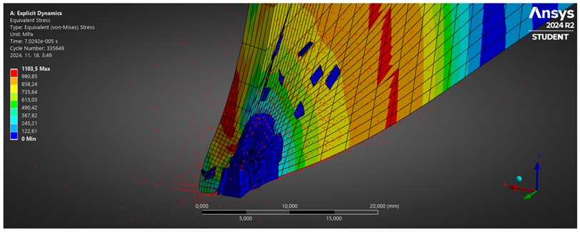
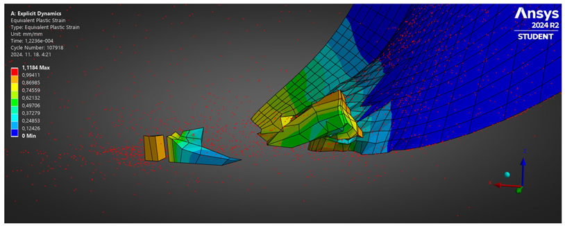
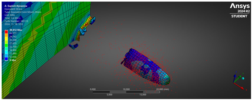
Snapshots of deformation contours and penetration progression are shown in Figures X–Y. Multi-angle impacts and repeated shots were also simulated using rotation matrices and velocity vector adjustment scripts within ANSYS Workbench. Polyurethane-bonded specimens showed consistent resistance even at 30° and 45° impact angles.
  • Mesh Convergence Study: Local mesh refinement (0.25 mm) was applied in the impact zone. Coarser meshes (1.0 mm) were used elsewhere. The solution remained stable under CFL-limited time steps.
  • Material Failure and Erosion: Johnson–Cook damage was combined with element deletion for materials exhibiting ductile fracture. For polymeric materials, an erosion strain threshold of 0.6 was applied.
  • Multiple Impact Simulation: For polyurethane-bonded laminates, six consecutive impacts were modeled by updating the internal stress state and re-applying bullet boundary conditions sequentially.
  • Binder Distribution: Although the simulations assumed uniform binder distribution, sensitivity tests were performed by applying graded elastic modulus regions to simulate non-uniformity (SEM-informed approximation).
Bullet-resistant materials are crucial in defense and security applications, requiring rigorous testing under extreme conditions. Numerical simulations provide a cost-effective and efficient alternative to physical testing. These simulations model high-speed impacts, material deformation, and failure mechanisms under ballistic loads. The simulations were carried out by 17.2 ANSYS Explicit Dynamics® software, which was designed to handle high-strain-rate problems, such as bullet impact on protective materials. The key features include the following:
  • Autodyn and LS-DYNA solvers for explicit finite element analysis (FEA).
  • Material models supporting metals, ceramics, composites, and layered armors.
  • Failure criteria and erosion models, such as Johnson–Cook, Tsai–Wu, and Drucker–Prager.
  • Contact algorithms for simulating projectile–target interaction.
  • Adaptive meshing to optimize computational efficiency.
A typical bullet impact simulation in ANSYS follows these steps:
  • Geometry and Meshing: Import CAD models of the bullet and target, applying fine meshing in critical regions.
  • Material Assignment: Select appropriate material models with dynamic properties.
  • Boundary Conditions and Loading: Apply velocity to the bullet and fixed constraints to the target.
  • Solver Settings: Use an explicit solver with small time steps to capture high-speed interactions.
  • Post-Processing: Analyze stress, strain, penetration depth, and failure zones.

2.2. Development of Simulation Models

A case study comparing ceramic-based composite armor with steel armor demonstrates the advantages of using ceramics: (i) Lower density, reducing overall weight; (ii) Higher hardness, leading to better projectile shattering; and (iii) Multilayer structure for improved energy dissipation. Simulation results show that ceramic layers reduce the projectile’s penetration depth compared to traditional steel armor [2,3].
The simulation was designed to closely resemble ballistic testing for realistic and accurate results. The assembly model used in the simulation consists of three components:
  • Core—The lead core of the bullet.
  • Jacket—The brass jacket of the bullet.
  • Plate—The material to be tested, with a thickness of 5.5 mm (representing the average thickness of the selected materials) and a surface area of 300 × 300 mm.
The bullet type used was 9 mm Parabellum FMJ, with dimensions taken from the research in [15] (see Figure 1).
Simulations were conducted on five different materials:
  • 34CrNiMo6 Steel (Steel 4340).
  • Al 7075-T6.
  • Rubber.
  • Nylon.
  • Polymethyl methacrylate (Plexiglass).
In ANSYS Explicit Dynamics, the solution of a high-velocity impact problem, such as a projectile penetrating a ballistic-resistant material, is based on the explicit time integration method using the central difference scheme [16,17]. The governing equations include the conservation of mass, momentum, and energy, which are solved incrementally in time.
a. 
Governing Equations
1. Conservation of Mass (Continuity Equation):
D ρ D t + ρ · · v = 0
2. Conservation of Momentum (Newton’s Second Law):
ρ D v D t = · σ + f
3. Conservation of Energy:
ρ D e D t = σ : · v · q
b. 
Time Integration Using the Explicit Central Difference Method
The explicit solver in ANSYS solves the equations using the central difference method for time integration:
v n + 1 2 = v n 1 2 + Δ t · a n
x n + 1 = x n + Δ t · v n + 1 2
where v is velocity, x is position, a is acceleration, and Δt is the time step, which is determined by the Courant–Friedrichs–Lewy (CFL) condition:
Δt ≤ l min/c
where l_min is the smallest element characteristic length and c is the material wave speed:
c = sqrt(E/ρ)
c. 
Material Modeling: Johnson–Cook Plasticity and Damage Criteria
For ballistic impact simulations, ANSYS often employs the Johnson–Cook material model to account for strain rate effects, thermal softening, and plastic deformation:
σ y = A + B · ε n · 1 + C ln ε ( 1 T m )
For failure, the Johnson–Cook damage criterion is used, where failure occurs when the accumulated damage parameter D exceeds one:
D = Δ ε p ε f
To capture projectile penetration, contact algorithms (such as penalty-based or kinematic contact) and erosion criteria (such as the element deletion method) are used when material failure occurs [6,17,18].
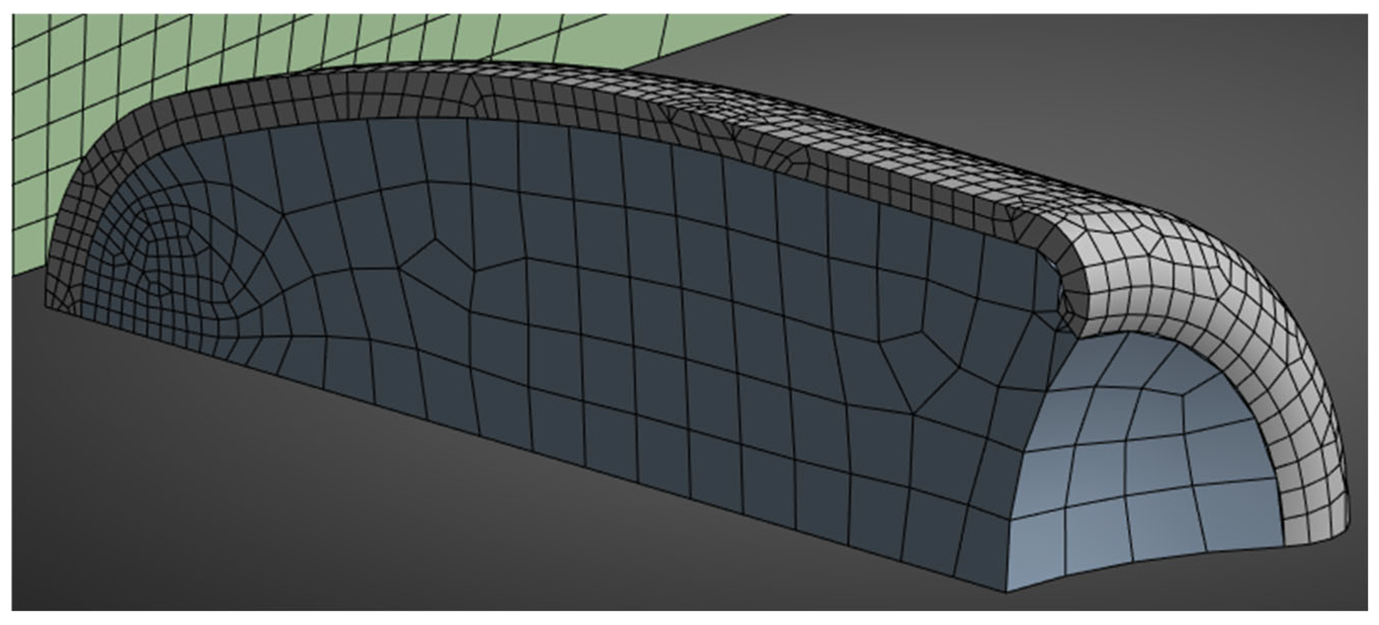
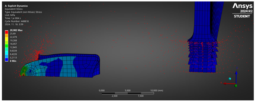
To increase computational efficiency, local mesh refinement was applied. This technique allows for larger mesh sizes in regions with minimal deformations or stress while using smaller mesh elements in areas where high deformations and stresses are expected. Mesh refinement was applied at the bullet tip and the impact zone of the plate (Figure 2).
The initial velocity and rotation of the bullet are key parameters in the simulation. The linear velocity was 383 m/s, based on the maximum velocity of the L3 ballistic resistance level, with a 10% safety margin. The rotation speed was given as n = 1000 rpm, typical for small arms [19,20].

2.3. Evaluation of Results

The results were analyzed in terms of penetration and bullet deformation. The summary of findings is presented in Table 2.

3. Experimental Section

3.1. Materials and Impact Specimen Configurations

Three configurations of impact specimens were tested. All specimens were made from 20-layer, 200 g Kevlar (aramid) fiber fabric (200 g/m2-plain CT709); WR-fabric KEVLAR29; or an equivalent vest ballistic para-aramid woven from fibers, used in the manufacture of bulletproof vests. This was a ballistic, 200 g/m2 weight, high-performance, lightweight, water-repellent (WR) aramid fiber fabric; it has become a standard and is widely used in the manufacture of bulletproof vests and protective clothing supplements. The properties of the CT709 Kevlar are summarized in Table 3.
The binder was applied by immersion, cured at 20 degrees Celsius for 15 min, and laminated at atmospheric pressure and 50% humidity. Heat treatment was carried out at 50 degrees Celsius for 3 h with a ramp time of 7 degrees Celsius per hour.
All specimens’ dimensions were 300 × 300 mm. The first specimen (Specimen 1) was made of 20 layers of aramid fabric without any binder. The second specimen (Specimen 2) was made of 20 layers aramid laminated with epoxy resin, and the third specimen (Specimen 3) was made of 20 layers aramid laminated with polyurethan resin. The properties of the epoxy and the polyurethan resin are summarized in Table 4. The mass and thickness data of the specimens are given in Table 5.

3.2. Structural Properties of Aramid Composites

The aim of this research was to improve the ballistic properties of the Kevlar. Two laminating materials, epoxy and polyurethane, were compared with an unlaminated test specimen. For the tests with epoxy and polyurethane binders, based on an earlier study, the distribution of the laminating material in the Kevlar fibers was not homogeneous in some places when examined by scanning electron microscopy. This is due to the fact that the laminating material cannot penetrate the gaps where the diameter of the single yarn is about 10 μm. The inhomogeneous distribution of the binder leads to a local deterioration of the ballistic properties. Figure 3 shows the microscopic surface morphology of each aramid composite after using a scanning electron microscope (SEM) at a magnification of 50 times and a magnification of 500 times.

3.3. Ballistic Impact Testing

The ballistics tests were conducted in the ballistics laboratory of the Hungarian Armed Forces according to the MSZ K 1114-1 1999 standard [21] (Table 6). The Hungarian MSZ K 1114-1:1999 standard specifies ballistic protection requirements for personal body armor used by law enforcement and military personnel. It defines protection levels based on resistance to specific projectile types, calibers, and velocities.
The international context is as follows:
NIJ (U.S.): The NIJ 0101.06 (and the updated 0101.07) [22,23] standards from the U.S. National Institute of Justice define ballistic resistance levels (e.g., Level II, IIIA, III, IV) based on specific handgun and rifle threats. MSZ K 1114-1 is roughly comparable, though not identical, in classifying protection levels by ballistic threats.
STANAG 2920 (NATO): This NATO standard [24] focuses on V50 ballistic limit testing —the velocity at which 50% of projectiles penetrate the armor. While MSZ K 1114-1 includes similar ballistic performance assessments, it is more prescriptive in threat levels than STANAG 2920, which is more of a testing methodology.
In summary, MSZ K 1114-1:1999 aligns with international standards in defining graded ballistic protection but is tailored to Hungarian threat assessments and legal requirements. It can be cross-referenced with NIJ and STANAG levels for interoperability and comparative analysis in multinational settings [25,26]. The standard provides the possibility to test both dry and wet specimens. It specifies a total of seven basic protection grades, from L1 to L6, with the addition of a special grade: LS.
The ballistics tests were carried out with a barrel inserted in the gun’s grip, which was also capable of accurate aiming, to eliminate the potential for error due to the human and mechanical design of the firearm. The ambient conditions during the tests were 23 degrees Celsius, 73% relative humidity, and 1.03 bar ambient air pressure. The test was conducted with a Blazer 9 × 19 mm Parabellum Luger bullet(Figure 4). The bullet was full metal jacket (FMJ), weighing 124 grains, or approximately 8.04 g. During firing, the velocity of the projectile was measured by two infrared light gates mounted between the test piece and the firearm.
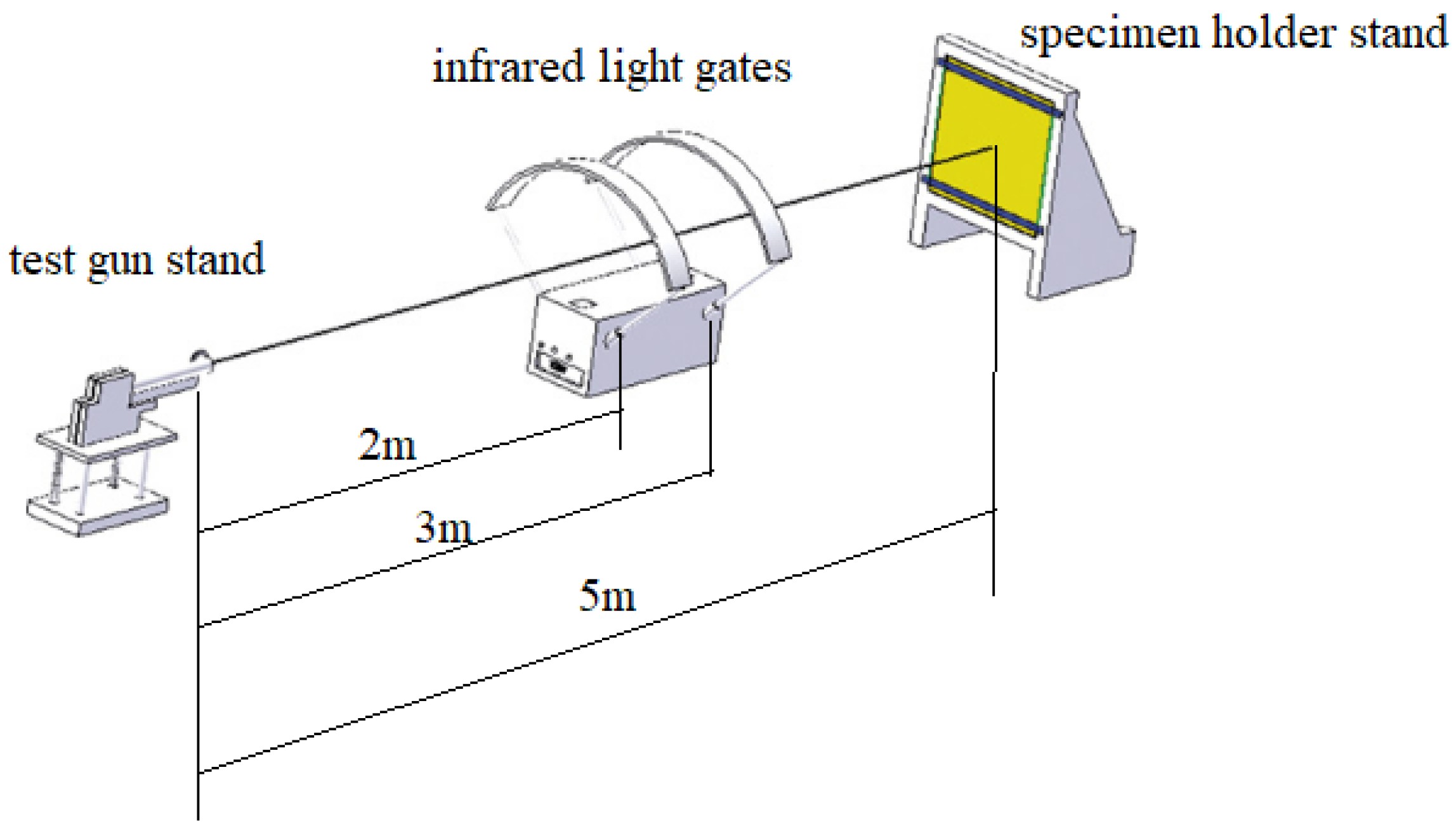
The standard specifies 5 m target distance for tests with a Parabellum bullet. The first light gate used for velocity measurement was located 2 m from the test weapon, and a distance of one meter was specified between the two light gates. The experimental setup for the MSZ K 1114-1 1999 standard level 4 is illustrated in Figure 5 [21].

4. Results and Discussion

4.1. Projectile Impact Analysis

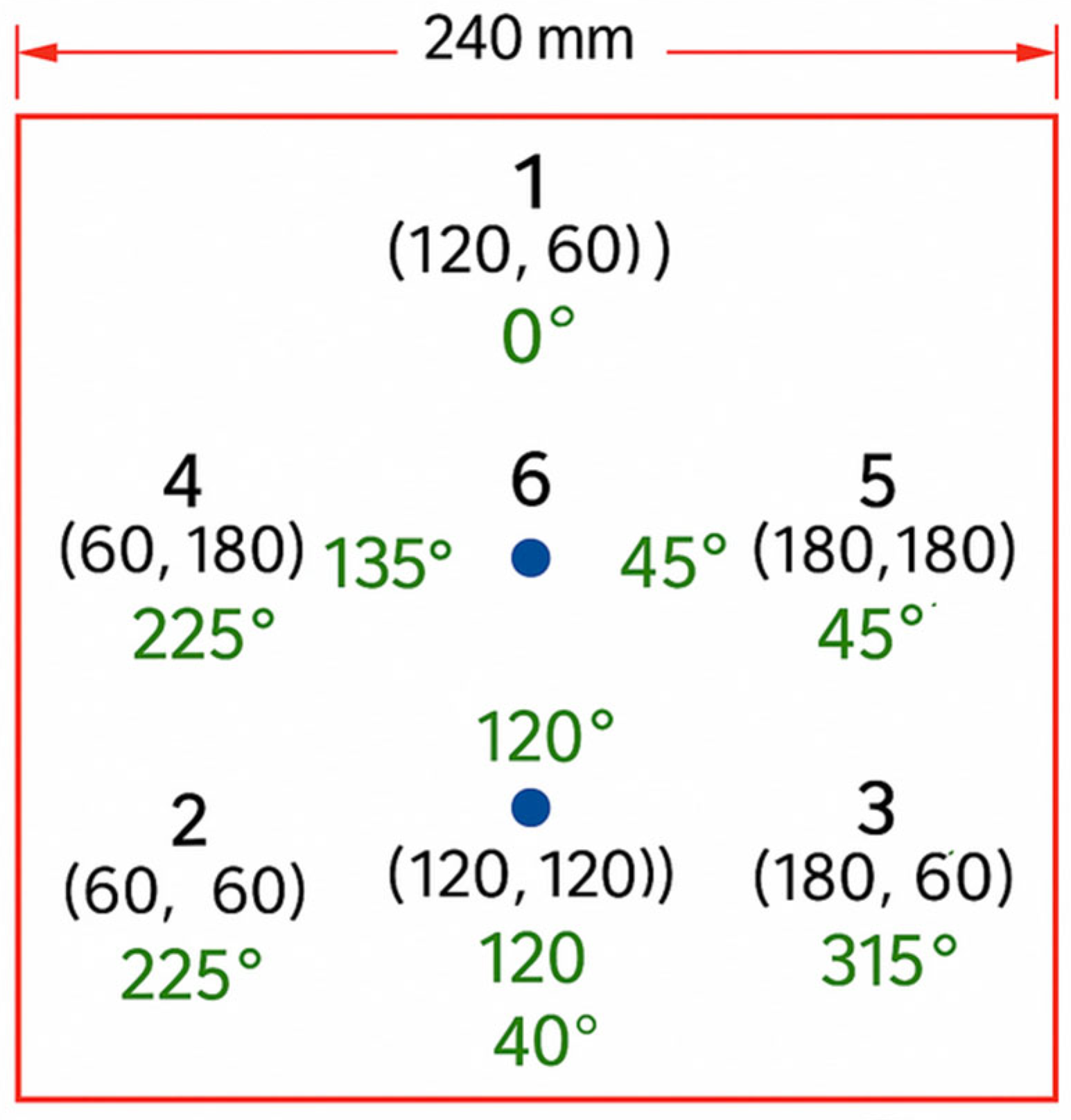
The standard MSZ K 1114-1 1999 distinguishes different protection levels. Here, protection level L4 was selected, which is capable of stopping a high-velocity, 8 g nominal weight, full metal-jacketed, lead-cored 9 mm Parabellum projectile at a velocity of at least 426 m/s. The test specimen meets level L4 if the projectile does not penetrate it and the trauma zone is less than 25 mm in the ballistic plasticine behind the specimen. The primary condition for test shots to be valid is that the hits hit the test piece. In addition, it is necessary that the hit is at least 76 mm from the edge of the test piece and, if there was a previous hit, that the new hit is at least 50 mm from the edge of the test piece. Other requirements are that the angle of impact must be within ±5° of the intended angle of impact, and the impact velocity of the projectile must not deviate by more than 15 m/s from the velocity specified in the standard. For protection level L4, the required impact velocity is 426 m/s. The standard includes a proposal for the location of hits (Figure 6).
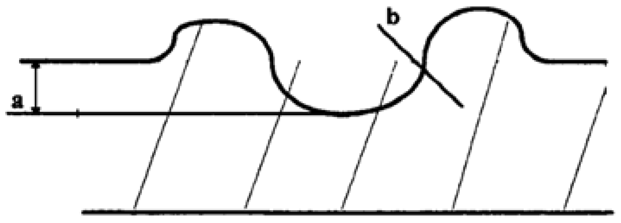
To measure the depth of the trauma zone, determine the upheaved part of the crater and the base plane and measure the depth (Figure 7).

4.1.1. Neat Kevlar Projectile Analysis

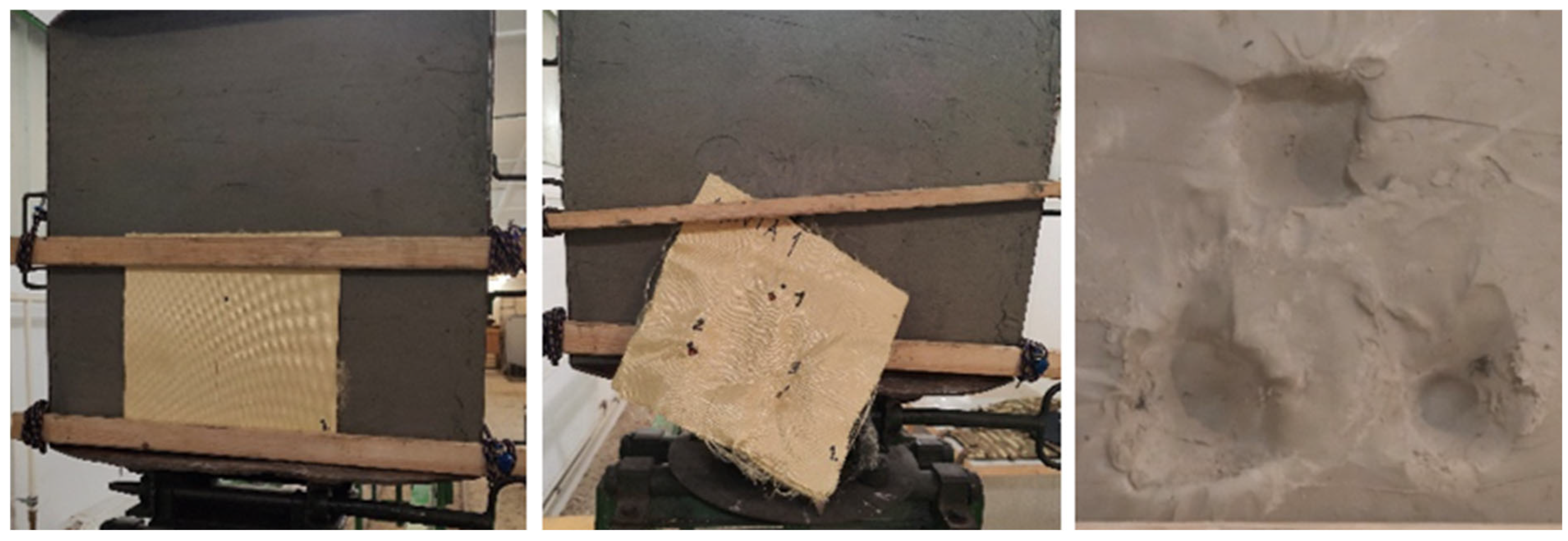
The specimen successfully caught the first shot, and the velocity of the projectile was 427 m/s. If the bullets cannot pass through the panels after shootings, a trauma is formed in the backing material at certain diameter and depth. The depth of this trauma shows the effect of the bullet transmitted to the back side of a panel. The tested panel was placed on a layer of plasticine in which the impression of the shot could be measured. The depth of the impression was 29.1 mm, which exceeded the permissible value of 25 mm, so the specimen did not meet the parameter required by the standard. After the first shot, two more shots were fired to test the deformation of the bullet and the panel. The neat Kevlar test specimen and the deformation following the shots, as well as the trauma zone, are illustrated in Figure 8.

4.1.2. Epoxy/Kevlar Projectile Analysis

The first shot at the test specimen was successful, and the projectile did not penetrate. The velocity of the projectile was 428 m/s. The depth of the trauma zone was 17.42 mm, thus meeting the standard depth. The second shots penetrated through the Kevlar and fell into the plasticine. The projectile velocity data and impression depths measured during the tests are shown in the Table 7.
The Epoxy/Kevlar test specimen and the deformation following the shots, as well as the trauma zone, are illustrated in Figure 9.

4.1.3. Polyurethane/Kevlar Projectile Analysis

The first three shots, fired at a 0° degree angle, proved that this composite performs well. The fourth and fifth shots were fired at an angle of +/− 30° degrees, and the sixth at was fired at 0 degrees again. The Polyurethane/Kevlar specimen passed all six standard shots, and the projectile did not penetrate. The trauma zone impression was within tolerance. The data are summarized in the Table 8.
The Polyurethane/Kevlar test specimen and the deformation following the shots, as well as the trauma zone, are illustrated in Figure 10.

4.2. Comparison of Projectile Deformation and Material Energy Absorption

After the ballistics tests, the specimens were examined, the number of penetrated aramid fiber layers were counted, and the projectiles were removed from the test specimens; then, their deformation was compared. Suitable bullet-resistant materials in the first layers of the test specimen cause a large deformation in the projectile to dampen the impact energy. If the projectile does not undergo any deformation, it will release all its kinetic energy through its tip at approximately one point. With deformation, however, the kinetic energy and impact force are distributed over a larger surface area, reducing the stresses in the material and allowing the projectile to stop. The projectiles side by side with the original projectile loaded in the barrel are shown in Figure 11.
The projectile fired into the neat Kevlar is the least deformed, which is visible in the depth of the impression it leaves. The material did not cause sufficient deformation in its first layers, so most of the kinetic energy was transferred in the direction of impact of the bullet, increasing the depth of the imprint. It can be concluded that the aramid fibers alone are not able to damp the impact sufficiently and that layers of binder or another material are needed.
The projectile fired into the Epoxy/Kevlar-reinforced specimen deformed the most, as reflected by the depth of the impression it left. The projectile was completely deflected, similar to the projectile fired into the steel plate in the simulation. This material had the smallest imprint depth. The hard layers of epoxy between and within the aramid fibers were able to produce a deformation sufficient to stop the bullet. However, the increased hardness of the material also caused the material to become brittle, which is evident in the second shot. At this point, the material could not stop the bullet [27,28].
Polyurethane demonstrates superior performance over epoxy in layered composite systems designed for ballistic protection, particularly in terms of energy absorption and structural integrity under high-velocity impact. One key factor is its higher elastic modulus—typically around 100 GPa compared to epoxy’s 75 GPa—which enables more effective stress distribution across the composite layers during projectile penetration. This enhanced stress transfer helps to dissipate impact energy more evenly, reducing localized failure and improving overall deformation behavior.
In addition, polyurethane exhibits significantly greater toughness, as indicated by its lower Shore hardness (approximately 30 versus 55 for epoxy). This higher ductility enhances the material’s ability to withstand interlayer delamination—a critical failure mode in laminated armor systems exposed to repeated ballistic threats. Enhanced toughness not only delays crack initiation but also hinders crack propagation across the laminate structure.
Analogous improvements in ballistic performance have been reported in shear thickening fluid (STF)-impregnated Kevlar systems, where the increased compliance and energy dissipation of the matrix improved projectile resistance and reduced fiber damage [29,30]. These findings support the conclusion that polyurethane’s viscoelastic nature and mechanical adaptability offer distinct advantages over more brittle resin systems like epoxy, especially in protective applications requiring multi-hit capability, energy dissipation under extreme strain rates, and long-term structural resilience.
The projectile struck the polyurethane-reinforced material and deformed relatively well. The deformation was more significant than that of the projectile of the superglued material, but it was smaller than that of the projectile of the epoxy-reinforced material. The depth of the impression also reflects this, with a smaller measurable distance from the impression depth of the clean material but a larger crater from the epoxy-reinforced material.
Cross-sectional images of projectiles fired into Epoxy/Kevlar and Polyurethane/Kevlar specimens are shown in Figure 12.

5. Conclusions

Simulation investigations and shooting tests in the laboratory have also confirmed that aramid fabric layers without a binder are unable to provide adequate protection against an impacting projectile. This study explores the use of ANSYS Explicit Dynamics for simulating the penetration of a bullet through various ballistic-resistant materials. This simulation provides a cost-effective alternative to physical testing by modelling high-speed impacts, material deformation, and failure mechanisms. The explicit finite element method (FEM) with central difference time integration is employed, ensuring accurate results for high-strain-rate problems. The Johnson–Cook plasticity and damage models are used to predict material failure, while contact algorithms and erosion criteria capture projectile–target interactions.
A case study compares the penetration resistance of different materials, including steel (4340), aluminum (7075-T6), rubber, nylon, and Plexiglass. Key parameters, such as initial bullet velocity (383 m/s) and rotational speed (1000 RPM), were considered.
  • The results highlight the effectiveness of ceramic composite armor in dissipating impact energy compared to conventional steel armor. Mesh refinement was applied to optimize computational efficiency in critical impact regions.
  • The study demonstrates that numerical simulations in ANSYS Explicit Dynamics can effectively predict ballistic performance, aiding in the design of advanced protective materials.
The test specimen made with epoxy binder deformed the projectile to the greatest extent, which shows its high energy absorption capacity.
  • Due to the hardness of epoxy, it is also brittle, which is also shown by the cracks formed around the impact zone. With the second shot, the material was no longer able to adequately absorb the energy of the projectile, which penetrated thought the specimen. The specimen prepared with polyurethane binder met the L3 protection level.
  • It was observed that the deformation of the bullet was greater than in the specimen without binder but less than in the specimen laminated with epoxy. The higher modulus of elasticity of the polyurethane resin proved to be suitable and performed adequately in the shooting test.
  • During the tests, the polyurethane binder proved to be the most suitable, so the specimens for further tests will be laminated with this material.
Polyurethane-bonded Kevlar composites offer promising potential for both military and civilian protective applications due to their superior energy absorption, flexibility, and resistance to delamination under high-velocity impacts. In military settings, such materials can be utilized in lightweight, multi-hit-capable body armor systems, combat helmets, and vehicle armor, where a balance between protection, mobility, and wearer comfort is critical. For civilian use, these composites are highly suitable for law enforcement gear, riot shields, and industrial protective equipment where resistance to puncture, impact, and repeated mechanical stress is required.
Future research should focus on optimizing the mechanical and ballistic performance of polyurethane matrices through advanced formulation strategies. One promising approach is the incorporation of nanoscale reinforcements (such as carbon nanotubes, graphene nanoplatelets, or silica nanoparticles), which have been shown to significantly enhance stiffness, toughness, and energy dissipation without compromising flexibility. Additionally, tailoring the phase morphology of segmented polyurethane elastomers could further improve microstructural energy dissipation mechanisms and crack-arrest capabilities. Investigating these strategies through systematic parametric studies, combined with real-world impact testing, would help in developing next-generation armor materials with enhanced performance and durability under extreme conditions.

Author Contributions

Conceptualization, I.P.K. and Z.F.K. Methodology, I.P.K. and Z.F.K. Software, J.L. Validation, Z.F.K. Formal Analysis, I.P.K. and J.L. Investigation, I.P.K. and Z.F.K. Resources, Z.F.K. Data Curation, I.P.K., J.L. and Z.F.K. Writing—Original Draft Preparation, I.P.K., J.L. and Z.F.K. Writing—Review And Editing, Z.F.K. Visualization, I.P.K., J.L. and Z.F.K. Supervision, I.P.K. Project Administration, I.P.K. and Z.F.K. Funding acquisition, Z.F.K. All authors have read and agreed to the published version of the manuscript.

Funding

This research received no external funding.

Data Availability Statement

The data presented in this study are available on request from the corresponding author. The data are not publicly available due to privacy.

Conflicts of Interest

The authors declare no conflict of interest.

Abbreviations

PBOPhenylene-benzobisoxazole
MSZ KHungarian Military Standard
FMJFull metal jacket
JSPJacketed soft-point bullet
RNRound nose
FNFlat nose
LLead
LRLong rifle
HVHigh velocity
SEMScanning electron microscope
SPCSpecial purpose cartridge
STFShear thickening fluid
WRWater repellent

References

  1. Othman, A.R.; Hassan, M.H. Effect of different construction designs of aramid fabric on the ballistic performances. Mater. Des. 2013, 44, 407–413. [Google Scholar] [CrossRef]
  2. Zhou, Y.; Chen, X. A numerical investigation into the influence of fabric construction on ballistic performance. Compos. Part B Eng. 2015, 76, 209–217. [Google Scholar] [CrossRef]
  3. Zhou, Y.; Yao, W.; Zhang, Z.; Lin, Y.; Xiong, Z.; Zhao, Y.; Wang, M. Ballistic performance of the structure-modified plain weaves with the improved constraint on yarn mobility: Experimental investigation. Compos. Struct. 2022, 280, 114913. [Google Scholar] [CrossRef]
  4. Khodadadi, A.; Liaghat, G.; Vahid, S.; Sabet, A.R.; Hadavinia, H. Ballistic performance of Kevlar fabric impregnated with nanosilica/PEG shear thickening fluid. Compos. Part B Eng. 2019, 162, 643–652. [Google Scholar] [CrossRef]
  5. Bilisik, A.K.; Turhan, Y. Multidirectional stitched layered aramid woven fabric structures and their experimental characterization of ballistic performance. Text. Res. J. 2009, 79, 1331–1343. [Google Scholar] [CrossRef]
  6. Li, H.; Zhang, R.; Min, S.; Zhou, Y.; Sun, J. Parametric study on the ballistic performance of seamed woven fabrics. Def. Technol. 2023, 24, 173–189. [Google Scholar] [CrossRef]
  7. Zhang, Y.; Tan, Y.; Liu, Z.; Wang, Y.; Sun, G. Modeling ballistic impact on nylon-based composites. Compos. Struct. 2020, 234, 111713. [Google Scholar] [CrossRef]
  8. Vescovini, A.; Cruz, J.A.; Ma, D.; Colombo, C.; Salerno, A.; Bianchi, O.; Amico, S.C.; Manes, A. Experimental investigation on low-velocity impact behavior of glass, Kevlar, and hybrid composites with an elastomeric polyurethane matrix. Compos. Part C Open Access 2024, 13, 100426. [Google Scholar] [CrossRef]
  9. Ghosh, A.; Das, S.; Das, A.; Mandal, N. Modeling dynamic behavior of 4340 steel using Johnson-Cook parameters. J. Mater. Res. Technol. 2020, 9, 3435–3446. [Google Scholar] [CrossRef]
  10. Rahman, M.; Ahmed, I.; Hasan, M.; Mahmud, S. Dynamic response of PMMA under high-velocity impact. Polym. Test. 2021, 93, 106954. [Google Scholar] [CrossRef]
  11. Gloger, M.; Stempien, Z.; Pinkos, J. Numerical and experimental investigation of the ballistic performance of hybrid woven and embroidered-based soft armour under ballistic impact. Compos. Struct. 2023, 322, 117420. [Google Scholar] [CrossRef]
  12. Johnson, G.R.; Cook, W.H. A Constitutive Model and Data for Metals Subjected to Large Strains, High Strain Rates, and High Temperatures. In Proceedings of the 7th International Symposium on Ballistics, The Hague, The Netherlands, 19–21 April 1983; pp. 541–547. [Google Scholar]
  13. Xu, H.; Zhang, Y.; Peng, R.; Zhu, L.; Lu, Y. Simulation and experimental study on the strength of Al7075-T6 clinched joint. Eng. Fail. Anal. 2021, 129, 105735. [Google Scholar] [CrossRef]
  14. ANSYS, Inc.: Ansys Fluent Theory Guide, Southpointe. 2021. Available online: https://dl.cfdexperts.net/cfd_resources/Ansys_Documentation/Fluent/Ansys_Fluent_Theory_Guide.pdf (accessed on 5 June 2025).
  15. Wiśniewski, A.; Gmitrzuk, M. Validation of Numerical Model of the Twaron® CT709 Ballistic Fabric. Probl. Mechatron. Armament Aviat. Saf. Eng. 2014, 5, 19–32. [Google Scholar]
  16. Wang, Z.; Zhang, H.; Dong, Y.; Zhou, H.; Huang, G. Ballistic performance and protection mechanism of aramid fabric modified with polyethylene and graphene. Int. J. Mech. Sci. 2022, 237, 107772. [Google Scholar] [CrossRef]
  17. Sockalingam, S.; Chowdhury, S.C.; Gillespie, J.W., Jr.; Keefe, M. Recent Advances in Modeling and Experiments of Kevlar Ballistic Fibrils, Fibers, Yarns and Flexible Woven Textile Fabrics—A Review. Text. Res. J. 2017, 87, 984–1010. [Google Scholar] [CrossRef]
  18. Min, S.; Chen, X.; Chai, Y.; Lowe, T. Effect of Reinforcement Continuity on the Ballistic Performance of Composites Reinforced with Multiply Plain Weave Fabric. Compos. B Eng. 2016, 90, 30–36. [Google Scholar] [CrossRef]
  19. Xu, Y.J.; Ma, Y.; Xie, Y.C.; Zhou, Y.; Zhang, H.; Huang, G.Y. Experimental and Numerical Study on the Ballistic Performance of a ZnO-Modified Aramid Fabric. Int. J. Impact Eng. 2023, 175, 104519. [Google Scholar] [CrossRef]
  20. Xu, F.; Fan, W.; Zhang, Y.; Gao, Y.; Jia, Z.; Qiu, Y.; Hui, D. Modification of Tensile, Wear and Interfacial Properties of Kevlar Fibers under Cryogenic Treatment. Compos. B Eng. 2017, 116, 398–405. [Google Scholar] [CrossRef]
  21. MSZ K 1114-1:1999; Ballistic Protection—Bulletproof Vests—Classification, Requirements and Test Methods. Hungarian Standards Institution: Budapest, Hungary, 1999.
  22. NIJ 0101.06; Ballistic Resistance of Body Armor. National Institute of Justice: Washington, DC, USA, 2008.
  23. NIJ 0101.07; Ballistic Resistance of Body Armor. National Institute of Justice: Washington, DC, USA, 2024.
  24. STANAG 2920; Ballistic Test Method for Personal Armour Materials and Combat Clothing. NATO Standardization Office (NSO): Brussels, Belgium, 2003.
  25. Karhankova, M.; Adamek, M.; Krstulovi’c-Opara, L.; Mach, V.; Bagavac, P.; Stoklasek, P.; Mizera, A. Composites in Ballistic Applications Focused on Ballistic Vests—A Review. J. Compos. Sci. 2024, 8, 415. [Google Scholar] [CrossRef]
  26. Tabiei, A.; Nilakantan, G. Ballistic Impact of Dry Woven Fabric Composites: A Review. Appl. Mech. Rev. 2008, 61, 010801. [Google Scholar] [CrossRef]
  27. Şenyilmaz, H.K.; Uslan, İ.; Demir, K. Investigation of the effect of a dilatant material on ballistic strength of aramid fabric used as body armour suit. J. Text. Inst. 2021, 113, 580–588. [Google Scholar] [CrossRef]
  28. Shih, C.-H.; You, J.-L.; Lee, Y.-L.; Cheng, A.-Y.; Chang, C.-P.; Liu, Y.-M.; Ger, M.-D. Design and Ballistic Performance of Hybrid Plates Manufactured from Aramid Composites for Developing Multilayered Armor Systems. Polymers 2022, 14, 5026. [Google Scholar] [CrossRef] [PubMed]
  29. Lee, Y.S.; Wagner, N.J. Dynamic properties of shear thickening colloidal suspensions in ballistic fabrics. J. Mater. Sci. 2003, 38, 2825–2833. [Google Scholar] [CrossRef]
  30. Decker, M.J.; Halbach, C.J.; Nam, C.H.; Wagner, N.J.; Wetzel, E.D. Stab resistance of shear thickening fluid (STF)-treated fabrics. Compos. Sci. Technol. 2007, 67, 565–578. [Google Scholar] [CrossRef]
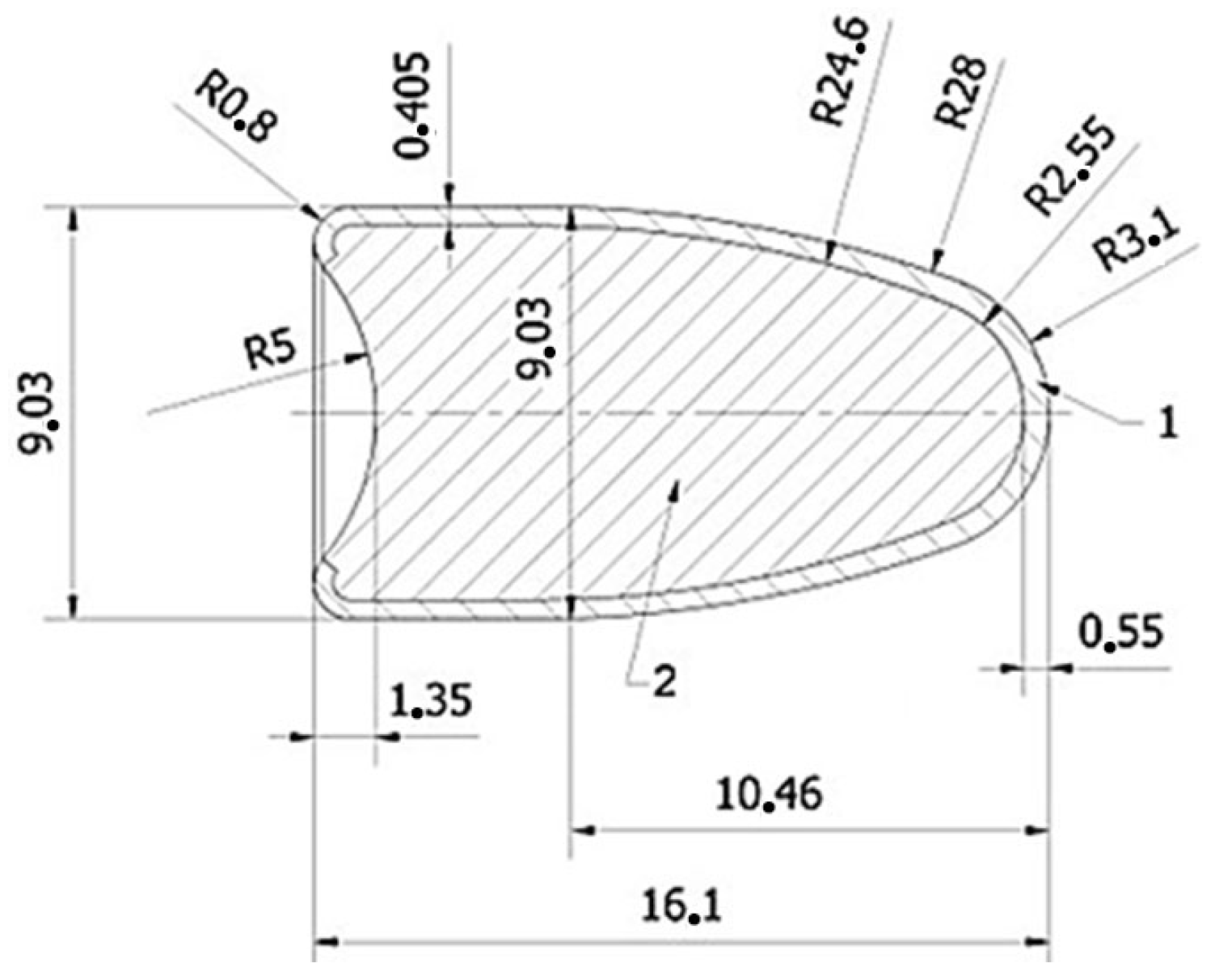
Figure 1. Dimensions of the 9 mm Parabellum FMJ bullet.
Fibers 13 00106 g001
Figure 2. Local mesh refinement.
Fibers 13 00106 g002
Figure 3. SEM pictures of the (a,b) Neat Kevlar plates; (c,d) STF/Kevlar plates; (e,f) Epoxy/Kevlar plates; (g,h) Polyurethane Elastomers/Kevlar plates.
Fibers 13 00106 g003
Figure 4. Experimental setup in the ballistics laboratory from left to right: infrared gates for measuring projectile velocity, gun barrel for firing 9 mm projectiles, gun stand.
Fibers 13 00106 g004
Figure 5. Experimental setup for MSZ K 1114-1 1999 standard level 4 [21].
Fibers 13 00106 g005
Figure 6. Projectile hit locations recommended by the standard MSZ K 1114-1 1999.
Fibers 13 00106 g006
Figure 7. Measurement procedure for the depth of the trauma zone (a—depth distance, b—ballistic plasticine).
Fibers 13 00106 g007
Figure 8. The neat Kevlar specimen before and after the shots, and the trauma zone.
Fibers 13 00106 g008
Figure 9. The Epoxy/Kevlar specimen before and after the shots, and the trauma zone.
Fibers 13 00106 g009
Figure 10. The Polyurethane/Kevlar specimen before and after the shots, and the trauma zone.
Fibers 13 00106 g010
Figure 11. Comparison of the projectiles: (a) original projectile, (b) projectile impacted in neat Kevlar, (c) projectile impacted in Epoxy/Kevlar, (d) projectile impacted Polyurethane/Kevlar.
Fibers 13 00106 g011
Figure 12. Cross-sectional images of projectiles fired into Epoxy/Kevlar (left) and into Polyurethane/Kevlar (right) specimens.
Fibers 13 00106 g012
Table 1. The explicit values for the J–C model parameters used in the ANSYS Explicit Dynamics environment.
MaterialA (MPa)B (MPa)NCMReference
Steel 4340 (34CrNiMo6)7925100.260.0141.03[9,12]
Al 7075-T65032600.260.0151.34[13]
Nylon95250.230.0151.0[7]
RubberJ–C not used, applied hyperelastic Mooney–Rivlin model [14]
PMMA (plexiglass)125900.30.021.2[10]
Table 2. Evaluation of simulation results.
MaterialPenetrationBullet DeformationFigure
Steel 4340NOFlatteningFibers 13 00106 i001
Al 7075-T6YESFragmentationFibers 13 00106 i002
RubberYESJacket RuptureFibers 13 00106 i003
NylonYESComplete Jacket SeparationFibers 13 00106 i004
PlexiglassYESJacket RuptureFibers 13 00106 i005
Table 3. Properties of the 200 g Kevlar (aramid) fiber fabric.
Parameter
Weight (g/m2)200
Density (g/cm3)1.45
Tensile strength (MPa)2400
Tensile modulus (GPa)90
Tensile strain (%)3.3
Table 4. Properties of the epoxy and the polyurethan resin.
ParameterEpoxyPolyurethan
Shore hardness5530
Density (cps)1.451.8
Tensile strength (MPa)303.5
Tensile modulus (GPa)75100
Equivalent weight (g/eq)140125
Viscosity (mPa·s)2001800
Table 5. Mass and thickness data of the specimens.
SpecimenMass (g)Thickness (mm)
13685.05
26545.48
36165.92
Table 6. The MSZ K 1114-1 1999 standards classification for bullet resistance [21].
Class Threat
Level
Type of Bullet
and Caliber
Minimum Bullet
Velocity
(m/s)
Number of Shots
00
Number of Shots
300
Minimum
Penetration Depth
(mm)
L10.38 Special RN2594244
L10.22 LR HV3204244
L20.357 Magnum JSP3814244
L29 × 19 mm FMJ Parabellum3324244
L30.357 Magnum JSP4254244
L39 × 19 mm FMJ Parabellum3584244
L444 Magnum SWC4264244
L49 × 19 mm FMJ Parabellum4264225
L57.62 × 54 R 39M L8386025
L67.62 × 54 R 39M B328681025
LSspecific requirementsdetermined by the customer
Table 7. Epoxy/Kevlar test data.
Number of ShotsProjectile Velocity (m/s)Angle of Shot (°)Depth of Trauma Zone (mm)Validity
1428017.42YES
24260-NO
3430019.25YES
Table 8. Polyurethane/Kevlar test data.
Number of ShotsProjectile Velocity (m/s)Angle of Shot (°)Depth of Trauma Zone (mm)Validity
1426023.2YES
2431024.8YES
3428022.25YES
4433−3023.5YES
5429+3024.5YES
6427022.84YES
Disclaimer/Publisher’s Note: The statements, opinions and data contained in all publications are solely those of the individual author(s) and contributor(s) and not of MDPI and/or the editor(s). MDPI and/or the editor(s) disclaim responsibility for any injury to people or property resulting from any ideas, methods, instructions or products referred to in the content.