Highlights
What are the main findings?
- Among the four hybrid configurations evaluated, the flax–glass–flax (LVL) laminate demonstrated the highest tensile strength and flexural deformation capacity.
- Its elastic behavior was reproduced through finite element modeling, showing close correlation with experimental results (≤0.86% stress error, ≤5.25% strain error).
- The orthotropic elastic properties of the LVL laminate were experimentally characterized and confirmed to be suitable for structural use in prosthetic applications.
What is the implication of the main finding?
- The LVL laminate offers a viable and more sustainable alternative to fully synthetic composites in load-bearing prosthetic components, maintaining mechanical reliability while incorporating natural fibers.
- The finite element model developed using the experimental data enables accurate simulation and design of hybrid composite prostheses.
- The proposed fabrication method—vacuum-assisted hand lay-up with additional weight—proves to be a practical and low-cost route for producing high-performance bio-composites.
Abstract
Four configuration laminates made of flax, glass, and basalt were fabricated via vacuum-assisted hand lay-up with added weight and tested under ASTM D3039 and D790. The flax–glass–flax lay-up exhibited the highest tensile strength and flexural strength. Orthotropic elastic properties were determined from remanufactured 90°-rotated specimens. A hexahedral-meshed finite element model using these inputs under a 5256 N load predicted the stress and strain within 1% and 5% of the experimental values. These findings demonstrate that flax–glass hybrids offer mechanical reliability, sustainability, and affordability for next-generation prosthetic applications.
1. Introduction
Prosthetic device development has changed dramatically over the last few decades, owing to advances in biomechanics and material science [1,2,3]. Because they were heavy and lacked biomechanical plasticity, early designs depended on inflexible monolithic structures composed of metal and wood [4,5]. Composite laminates and polymeric materials have made it possible for contemporary prosthetic devices to offer greater energy return and storage, increased longevity, and decreased weight [6,7].
High-performance prosthetic limbs are typically made of composite materials, especially those reinforced with synthetic fibers such as carbon and glass [7,8,9,10,11,12]. These materials have notable strength-to-weight ratios and can be laminated to customize their mechanical properties. However, interest in sustainable substitutes, such as natural fiber-reinforced composites, has increased owing to the expense and environmental effects of synthetic fibers [13,14,15,16,17,18,19,20,21].
Hybrid laminates, which incorporate both natural and synthetic fibers, present an approach that balances mechanical performance, sustainability, and cost-effectiveness [21,22,23,24,25]. The strategic combination of fibers, such as flax, hemp, or basalt, with traditional carbon or glass reinforcements can enhance energy absorption, improve damping characteristics, and provide an eco-friendly alternative to fully synthetic composites [25,26,27,28,29].
Hybrid laminates used in prosthetic devices need to have high flexural strength, fatigue resistance, and the right amount of stiffness to mimic the biomechanical characteristics of human biomechanics [12]. Choosing the right fiber type, resin matrix, and laminate stacking pattern is essential for performance optimization. According to recent studies, hybrid topologies can achieve mechanical qualities similar to those of traditional synthetic fiber composites, which makes them appropriate for prosthetic applications [1,10,13].
Despite advances in prosthetic materials, the development and mechanical validation of sustainable hybrid composites that combine natural and synthetic fibers while achieving mechanical performance comparable to fully synthetic laminates remains a significant challenge. In this study, four different hybrid laminate configurations were fabricated and mechanically tested. Among these, the flax–glass–epoxy laminate demonstrated superior performance and was subsequently selected for detailed mechanical characterization and validation through numerical simulation. Our results demonstrate that this hybrid laminate can achieve competitive mechanical properties, offering a sustainable alternative with a reduced environmental impact compared to conventional synthetic composites. This study provides a comprehensive evaluation of the laminate’s mechanical behavior through standardized testing and introduces a validated finite element model to predict its performance in prosthetic applications. Collectively, these contributions offer a viable pathway toward high-performance, eco-friendly materials for prosthetic device manufacturing.
2. Materials and Methods
2.1. Materials
Fibers and Resin Specifications
A combination of synthetic and natural fibers embedded in a polymeric matrix was used to create hybrid laminates. Because of their superior mechanical qualities and advantages for the environment, flax (from RockWest Composites, San Diego, CA, USA, 2 × 2 twill weave, 365 GSM) [30,31,32,33,34,35,36] and basalt [29,35,37,38] fibers were selected as the natural reinforcements; glass fiber (from Fibre Glast, Brookville, OH, USA, 8H satin weave, weight: 305.15–345.84 GSM) was chosen because of its high strength-to-weight ratio [29,39,40,41]. An epoxy resin (Epoxy Resin 2000 with Catalyst 2021 from Fibre Glast) system was used to create the matrix because of its excellent mechanical performance and good fiber adherence [1,12,42,43,44,45].
2.2. Sample Preparation
2.2.1. Laminated Configurations (Hybrid Compositions)
The laminate configurations were adapted from the design proposed by Song et al. [6], incorporating different stacking sequences of flax, basalt, and glass fibers to optimize mechanical performance. The configurations were as follows:
- BLB: Basalt [±45] + Flax 8@[90] + Basalt [±45];
- LBL: Flax [±45] + Basalt 8@[90] + Flax [±45];
- VLV: Glass [±45] + Flax 8@[90] + Glass [±45];
- LVL: Flax [±45] + Glass 8@[90] + Flax [±45].
Each laminate consisted of 12 layers in total, with the outermost two layers on both sides oriented at ±45° and the inner eight layers oriented at 90°. This stacking sequence ensured a symmetrical and balanced laminate structure. Although the stacking sequence remained the same across all four laminates, the constituent materials varied according to the specified configurations, affecting the mechanical behavior of each laminate.
2.3. Manufacturing Process
2.3.1. Vacuum-Assisted Hand Lay-Up with Added Weight
The laminates were manufactured using a vacuum-assisted hand lay-up technique with additional weight (see Figure 1) to ensure proper fiber impregnation and reduced void content. Layers of fibers were manually arranged in the specified stacking sequences, impregnated with epoxy resin, and then subjected to vacuum pressure. The resin-to-catalyst ratio was maintained at 100:27 by weight as specified by the manufacturer. Each laminate was left to cure at room temperature for approximately 48 h. The final laminate size was 12 × 9.25 inches to accommodate six test specimens of the dimensions required by ASTM D3039 and ASTM D790.
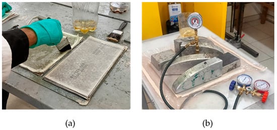
Figure 1.
Hand lay-up: (a) assisted vacuum bagging with added weight and (b) the method used to manufacture the proposed laminates.
2.3.2. Laminate Preparation and Cutting
After the curing process, each laminate was trimmed to ensure uniformity and proper alignment of fiber layers. The laminates were marked and cut into test specimens. The tensile test specimens (ASTM D3039 [46]) measured 10 × 1 inches with a span support of 5.645 inches, while the flexural test specimens (ASTM D790 [47]) were cut with a width of 0.5 inches and lengths based on laminate thickness for a 32:1 span-to-depth ratio. The calculated span supports used for the flexural tests were BLB = 9.667 inches, LBL = 6.986 inches, VLV = 9.142 inches, and LVL = 6.202 inches. Six specimens were cut from each laminate for each ASTM test, using an 8-inch carbide cutting disk. The process began by marking and identifying each specimen on the laminate surface, followed by marking the cutting guides and manually cutting each specimen. A total of 48 specimens were obtained, with six allocated for each ASTM test, totaling 12 specimens per laminate configuration (see Figure 2).
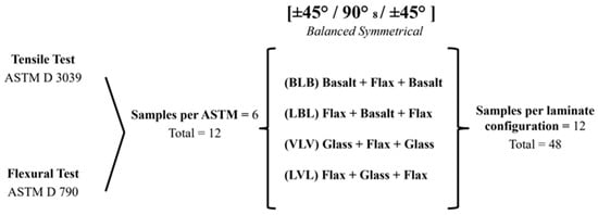
Figure 2.
Distribution and total number of test specimens required according to the type of test and laminate configuration.
2.4. Mechanical Testing
2.4.1. Tensile and Flexural Testing of Hybrid Laminates
Six test specimens were tested under both tensile and flexural loading conditions. Tensile testing was conducted according to ASTM D3039 using a Universal Testing Machine from Physical Test Solutions (Physical Test Solutions, Culver City, CA, USA). (https://www.physicaltestsolutions.com/) (accessed on 4 April 2025) with PTS MaxTest software for controlling, testing, and data acquisition. Tensile tests were performed under a constant crosshead speed of 2 mm/min until specimen failure, as specified by ASTM D3039 (see Figure 3a).
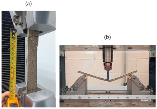
Figure 3.
Tensile (a) and flexural (b) failure test specimens tested according to ASTM D3039 and D790.
Flexural testing followed ASTM D790 standards using a SHIMADZU AG-IC 100 kN Universal Testing Machine (Shimadzu Corporation, Kyoto, Japan) (https://www.shimadzu.com/) (accessed on 4 April 2025) with TRAPEZIUM X software for control and data acquisition. Flexural tests were performed as three-point bending tests with a constant crosshead speed of 2 mm/min until specimen failure or 5% strain, whichever occurred first (see Figure 3b). The load and displacement data were captured for analysis, and the results were averaged from six specimens per laminate configuration for each test type for statistical reliability.
2.4.2. Statistical Analysis for Laminate Performance Comparison
To determine the best-performing laminate configuration based on tensile strength, a statistical analysis was conducted prior to evaluating the orthotropic properties. A one-way Analysis of Variance (ANOVA) was performed to assess whether significant differences existed among the four tested laminate configurations: BLB, LBL, VLV, and LVL.
The analysis was based on the tensile strength values obtained from six specimens per laminate configuration, in accordance with ASTM D3039. Statistical computations were conducted using Microsoft Excel, with a significance level of α = 0.05. ANOVA was used to compare the tensile strength values across the four groups to identify statistically significant differences.
The results revealed a significant difference in the tensile performance among the proposed configurations, with the LVL laminate exhibiting superior mean strength. No post hoc tests were applied because the ANOVA results were sufficient to identify the LVL laminate as the statistically best-performing configuration. This justified the selection of the LVL laminate for remanufacturing and detailed orthotropic characterization for numerical simulation validation.
2.4.3. Determination of Orthotropic Properties for the Best-Performing Laminate
Following the statistical analysis of the tensile and flexural test results (see Section 3. Results and Discussion for more details), the LVL laminate configuration was identified as the best-performing laminate owing to its superior mechanical properties. To further characterize its orthotropic mechanical properties, the LVL laminate was remanufactured using the vacuum-assisted hand lay-up method described previously (as discussed in Section 2.3. Manufacturing Process). Because only a single-axis testing machine was available, an additional LVL laminate was produced with fiber orientations rotated by 90° to determine the transverse mechanical properties (see Figure 4).
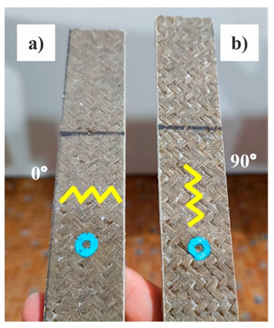
Figure 4.
Test specimens of the LVL laminate, with the original orientation of the layers (a), and rotated 90° (b). The yellow lines indicate the difference between the two laminates.
Both laminates were subjected to tensile tests according to ASTM D3039 (as described in Section 2.4.1. Tensile and Flexural Testing of Hybrid Laminates), one with the original stacking sequence to obtain longitudinal properties (see Figure 4a) and the other with the rotated sequence to approximate transverse properties (see Figure 4b). The tensile tests for both laminates were performed using the HOYTOM HM-D Lab Series testing machine (Hoytom S.L., Leioa, Bizkaia, Spain) (https://www.hoytom.com/) (accessed on 5 April 2025) equipped with a VECTOR uniaxial digital extensometer (Imetrum Limited, Wraxall, Bristol, United Kingdom) (https://www.imetrum.com/vector-extensometers/) (accessed on 5 April 2025) and controlled using HoyWin software. As in previous tests, each laminate was used to extract six specimens of 10 × 1 inches, totaling 12 specimens (six for longitudinal and six for transverse properties), manufactured, marked, and cut as described in previous sections. This process enabled the determination of the key orthotropic parameters necessary for the accurate modeling and analysis of laminates using FEA.
2.5. Finite Element Analysis
2.5.1. Simulation of Tensile Behavior for Validation
To validate the orthotropic mechanical properties determined through the experimental tensile testing, FEA was conducted to replicate the tensile behavior of the LVL laminate. The objective of the FEA validation was to compare the simulated stress–strain response with the experimental results, ensuring consistency and reliability of the measured elastic properties.
A 3D model of the test specimen was developed using the average dimensions of the real LVL test subjects. The total length of the specimen was 254 mm (10 inches), with a calibrated area length of 142.24 mm (5.6 inches), a width of 26.50 mm (1.04 inches), and a thickness of 6.51 mm (0.2563 inches). The elastic orthotropic properties used in the simulation corresponded to the average values obtained from LVL tensile tests (see Section 3.2. Orthotropic Properties of the Selected Hybrid Laminate). However, because test subject 2 exhibited a significant deviation from the other five specimens in the elastic region of the laminate, its mechanical properties were excluded from the averaging process. Given that the LVL stacking sequence exhibited quasi-isotropic behavior, the elastic modulus was assumed to be equal in all directions (), and Poisson’s ratio was also treated as equal in all directions (). The final orthotropic material properties used in the simulations are presented in Table 1. The tensile load applied in the simulation was 5255.62 N, which corresponded to the average force at which the LVL laminate reached its elastic limit in the experimental tests. The average elastic stress limit used in the FEA was 30.695 MPa.

Table 1.
Orthotropic elastic properties used in the LVL test subject 3D finite element model.
The 3D model was meshed using hexahedral elements to ensure a high accuracy in the stress and strain calculations. A global element size of 3 mm was used, and the calibrated area was refined with 1 mm hexahedral elements to improve the local stress and strain resolution. The final model contained 132,780 nodes and 28,242 elements, with skewness close to zero and orthogonality values near one, ensuring a well-conditioned mesh for numerical accuracy. As part of the model calibration process, a correction factor of 1.2 was given to both the orthotropic elastic modulus and the shear modulus to compensate for model uncertainty, even though the original material properties provided a close approximation of the experimental results. The calibration process is necessary to compensate for real factors not taken into account in the simulation due to the simplification and idealization process, such as material anisotropy, minor errors in the boundary conditions, localized stress concentrations, or manufacturing defects that were not adequately represented in the experimental configuration.
FEA was performed under the same boundary and loading conditions as the experimental tensile test (see Section 2.4.1. Tensile and Flexural Testing of Hybrid Laminates) to ensure an accurate comparison between the numerical and physical results (Figure 5). The boundary conditions of one end face of the virtual test specimen were fully constrained to simulate the fixed grip of the testing machine, whereas a longitudinal tensile load was applied to the opposite end face, replicating the axial loading conditions used during the experimental procedure. The two mechanical parameters used for the validation were the average elastic limit in the calibrated area of the test specimen and the maximum longitudinal displacement of the central region (50 mm gauge length) of the calibrated section. The finite element model resulted in a stress of 30.427 MPa, which was compared to the experimental average of 30.69 MPa with an error of 0.86%. In contrast, the maximum longitudinal displacement obtained in the simulation was 0.032992 mm, resulting in a calculated strain of 0.0006598. A strain error of 5.25% was obtained compared to the experimentally measured strain of 0.0006269.
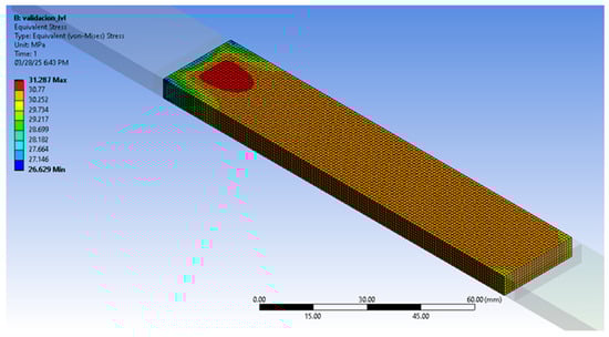
Figure 5.
Stress test and simulation setup of the LVL laminate 3D test subject model in ANSYS 2019 R3.
The stress distribution and deformation patterns observed in the simulation closely matched those observed in the physical specimens (Table 2), thereby reinforcing the validity of the experimental characterization. These findings demonstrate that the finite element method can effectively predict the elastic response of the LVL laminate, supporting the accuracy of the experimental results. The validated orthotropic properties can be further utilized in computational models for the structural performance analysis and design optimization of similar hybrid laminates in engineering applications.
Table 2.
Experimental versus simulated LVL validation results.
3. Results and Discussion
3.1. Mechanical Properties of Hybrid Laminates
3.1.1. Tensile and Flexural Behavior
The tensile and flexural behaviors of the four hybrid laminates (BLB, LBL, VLV, and LVL) were evaluated using data from the ASTM D3039 and ASTM D790 tests. The tensile strength, tensile strain, flexural strength, and flexural strain values for each laminate are summarized in Table 3.
Table 3.
The tensile and flexural mechanical properties of the tested laminates were determined according to ASTM D3039 and ASTM D790.
The LVL laminate exhibited the highest tensile strength (187.79 ± 8.02 MPa), while the VLV configuration achieved the highest flexural strength (109.94 ± 7.92 MPa), which was not significantly different from that of the LVL (91.31 ± 8.43). Notably, LVL reached a flexural strain exceeding 5% without failure, demonstrating a greater capacity for deformation prior to fracture. Overall, LVL showed a better mechanical response than the other configurations in terms of tensile and flexural performance. The stress–strain curves for all laminates, shown in Figure 6, highlight LVL’s load-bearing capacity and flexibility.
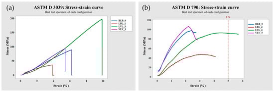
Figure 6.
Stress–strain curves of both the test tension (a) and flexion (b) for the best test specimen from each laminate configuration.
The superior performance of the LVL laminate in tensile testing can be attributed to the balanced combination of flax and glass fibers, which enhanced both stiffness and strength. Statistical analysis confirmed that the LVL configuration surpassed the other laminates (p < 0.05, as supported by ANOVA results F(3, 17) = 819.111 and a p-value of 1.41 × 10⁻¹⁸), indicating a clear difference in tensile strength across configurations. For detailed data on the statistical analysis, refer to Section 2.4.2. Statistical Analysis for Laminate Performance Comparison.
In the flexural test, the LVL laminate also demonstrated high resistance to bending deformation (see Figure 7), with minimal or no delamination and consistent load distribution throughout the test. In contrast, the BLB and VLV laminates exhibited moderate mechanical behavior, whereas the LBL laminate exhibited the lowest tensile and flexural strengths, likely due to its fiber composition and stacking orientation.
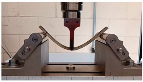
Figure 7.
Bending test of an LVL specimen according to ASTM D 790.
The results demonstrate that hybrid laminates with balanced fiber orientations and well-selected material combinations, such as the LVL configuration, are strong candidates for prosthetic applications, offering both mechanical strength and flexibility. A comparison with similar studies shows that the performance of the LVL laminate aligns well with previous findings on hybrid composites for structural applications. For instance, Dong [48] reported that optimal mechanical behavior can be achieved by placing flax fibers in the mid-plane and glass fibers in the outer layers, an approach that mirrors the LVL stack-up (see Section 2.2.1. Laminated Configurations). This configuration not only enhances the mechanical properties but also supports the integration of flax fibers owing to their sustainability benefits. Das et al. [49] and Hinzmann et al. [50] similarly affirmed the mechanical and ecological advantages of combining flax and glass fibers. The tensile strength and modulus values obtained in this study fall within the ranges reported in related studies [9,39,51], with LVL exceeding comparable laminates in both tensile and flexural tests. These consistent results reinforce the validity of the current findings and highlight the relevance of hybrid flax–glass laminates in prosthetic device development.
3.1.2. Performance Ranking Based on Mechanical Suitability
To establish a comparative ranking among the four proposed hybrid laminate configurations (BLB, LBL, VLV, and LVL), the results from the mechanical testing were assessed based on their overall performance in terms of both tensile and flexural properties. The comparison aimed to identify the most mechanically suitable laminate for structural applications while factoring in the sustainability contribution of natural fibers. The performance ranking was primarily based on the combination of the tensile strength and flexural strength values obtained through the ASTM D3039 and ASTM D790 tests (see Section 3.1.1. Tensile and Flexural Behavior).
The LVL laminate consistently demonstrated the highest mechanical performance in both tensile and flexural tests, achieving higher results than the other laminates. As detailed in the statistical analysis, the tensile strength of the LVL laminate (187.79 ± 8.02 MPa) was found to be approximately twice as high as the nearest hybrid competitor (VLV, 89.62 ± 3.69 MPa), with the ANOVA test confirming its statistical significance at p < 0.05 (see Section 2.4.2. Statistical Analysis for Laminate Performance Comparison).
To further validate the superior performance of the LVL laminate and estimate its orthotropic properties, a second set of LVL laminates was remanufactured following the fabrication method described previously (see Section 2.3. Manufacturing Process). The remanufactured LVL laminate was subsequently tested along both the longitudinal and transverse directions to determine its orthotropic properties (detailed in Section 2.4.3. Determination of Orthotropic Properties for the Best Performing Laminate). The consistent mechanical behavior observed in the remanufactured laminates reinforced the LVL configuration as the best-performing hybrid composition.
Thus, the use of flax fiber in the hybrid laminate composition is a good way to improve sustainability without sacrificing the mechanical performance. These results align with research that showed that the benefits of hybrid composites containing natural fibers are not only mechanical but also environmental, particularly flax [32,33,35,36,52] and kenaf [1,53]. By adding flax fibers to the LVL laminate, the mechanical performance was improved, and the use of natural fibers as a sustainable alternative material for structural applications was further supported. Based on these findings, the final performance ranking of the hybrid laminates, in terms of both mechanical suitability and sustainability factors, was as follows: (1) LVL, (2) VLV, (3) BLB, and (4) LBL.
3.2. Orthotropic Properties of the Selected Hybrid Laminate
Following a statistical comparison of the mechanical properties obtained from the hybrid laminates (see Section 3.1.2. Performance Ranking Based on Mechanical Suitability), the LVL laminate configuration exhibited the best performance in both the tensile and flexural tests. Consequently, this laminate was selected for determining its orthotropic properties. Two separate laminates were manufactured using the same method previously described, one for determining the longitudinal properties and the other for determining the transverse properties by rotating the stacking sequence at 90° (detailed in Section 2.4.3. Determination of Orthotropic Properties for the Best Performing Laminate).
The group of specimens tested from the original laminate was used to obtain the longitudinal mechanical properties, whereas the rotated laminate specimens were used to approximate the transverse mechanical properties. Owing to the quasi-isotropic nature of the stacking sequence, the variation between these properties is expected to be minimal. The directly measured parameters were the longitudinal modulus , transverse modulus , maximum load, maximum stress, and maximum strain of the longitudinal group. The shear moduli and were estimated using empirical equations based on the measured elastic modulus values. Poisson’s ratios and were obtained from averaging values from literature [25,26,29,31,32,33,34,36,40,52,54,55,56,57,58].
According to the findings (see Table 4), the LVL laminate has better mechanical qualities than several natural fiber composites documented in the literature. Its 75.56 ± 13.39 GPa longitudinal modulus is higher than the 17.33–32 GPa values found in flax/epoxy [33,54] and flax/basalt/epoxy [35] composites. Comparably, the transverse modulus of 71.26 ± 6.57 GPa is greater than that of Abida et al.’s [34] flax/epoxy (4.7 GPa) and Lian et al.’s [44] and Almula et al.’s [25] glass/epoxy composites (10.1–11.3 GPa). These findings imply that the LVL design offers more stiffness, most likely as a result of the fibers’ optimal orientation and the interplay between flax and glass fibers.
Table 4.
Elastic and strength properties of orthotropic LVL laminate.
The LVL laminate also performed better than the published hybrid natural fiber composites in terms of shear characteristics. The flax/basalt/epoxy hybrid laminate from Giammaria et al. [35] was between 0.8 and 2.65 GPa, which was exceeded by the LVL in-plane shear modulus, reaching 37.66 GPa. At 26.39 GPa, the out-of-plane shear modulus was comparatively high, exceeding the values found in glass/basalt/epoxy hybrid composite from Almula et al. [25], which was 3.35 GPa. These results suggest that the LVL laminate is a promising option for structural applications when multi-axial stress conditions are anticipated, due to its high resistance to shear deformation.
In terms of strength characteristics, the LVL laminate shows a maximum stress of 153.06 ± 4.55 MPa, which is higher than the values documented for hybrid laminate made of kenaf/jute/epoxy (88.08 MPa) [28]. Natural fiber composites, such as Moudood et al.’s [32] flax/epoxy, projected a range of maximum strain of 1.87–2.64%, which is comparable even though their laminate was made only by ten flax layers. Overall, the results confirm that the LVL hybrid laminate offers significant improvement over traditional natural fiber-reinforced composites in terms of stiffness, shear resistance, and strength. These enhancements make it a viable and sustainable alternative for engineering applications that require high mechanical performance while maintaining eco-friendly material composition.
3.3. Finite Element Validation of Tensile Behavior
The finite element model, developed to replicate the tensile behavior of the LVL laminate (as described in Section 2.5.1. Simulation of Tensile Behavior for Validation), showed agreement with experimental measurements. The simulation, which employed an adjustment factor of 1.2 to both the orthotropic elastic and shear moduli, yielded an average stress of 30.427 MPa—very close to the experimental average of 30.69 MPa (error of 0.86%). Moreover, the maximum longitudinal displacement in the simulation, when converted to strain over the 50 mm gauge length, produced a strain value of 0.0006598, compared to the experimental measurement of 0.0006269, corresponding to an error of 5.25% (see Table 2).
These findings confirm that the finite element analysis reliably predicts the elastic response of the LVL laminate. The close correlation between the simulated and experimental stress–strain data reinforces the validity of the measured orthotropic properties and demonstrates the effectiveness of the model in capturing the mechanical behavior of the laminate within the elastic range. Moreover, the reliability of the finite element model suggests that this approach can be extended to predict the mechanical elastic behavior of prosthetic 3D models and to test such models under various loading scenarios in future studies. Similar processes have been successfully employed to assess prosthetic foot materials, as reported in studies by Santana et al. [12], Sehar et al. [9], and Song et al. [6]. In contrast, studies such as those by Mankai et al. [17] and Nurhanisah et al. [1] have similar approaches, but for the socket made of fibers extracted from the alfa plant and kenaf, respectively.
4. Conclusions
Tensile and flexural characterizations of the four hybrid laminates revealed that the flax–glass–flax (LVL) configuration exhibited higher strength and stiffness compared to the other configurations. When remanufactured and tested in both the longitudinal and transverse directions, LVL exhibited a longitudinal modulus of 75.6 GPa and a transverse modulus of 71.3 GPa, with shear moduli of 37.7 GPa (in-plane) and 26.4 GPa (out-of-plane). Finite element simulations using these orthotropic properties—after applying a 1.2 correction factor to compensate for model uncertainty—predicted an average stress within 0.86% and a strain within 5.25% of the experimental results. The mesh quality (132,780 nodes, 28,242 hexahedral elements with skewness ≈ 0 and orthogonality ≈ 1) and the consistency between the numerical simulation and physical data support the accuracy and applicability of the mechanical model inside the elastic range.
By combining flax and glass fibers in a symmetrically balanced lay-up, the LVL laminate achieved a balance between sustainability and mechanical performance. The incorporation of natural flax fibers reduces raw material costs, and the use of vacuum-assisted hand lay-up with added weight proves to be a low-cost and effective manufacturing route for hybrid composites. These findings demonstrate the potential of hybrid laminates to meet the demands of load-bearing prosthetic components while minimizing both the ecological footprint and manufacturing cost.
Importantly, this study provides a novel contribution to the literature by integrating experimental and numerical methods to validate the orthotropic properties of flax–glass hybrid laminate tailored specifically for prosthetic applications. While natural fiber composites have been explored in various structural contexts, this study advances the field by focusing on biomechanical relevance and demonstrating their feasibility for use in prosthetic limbs.
Nevertheless, the limitations of this study must be acknowledged. The finite element validation was based on a single average experimental specimen, and confidence intervals could not be applied to the simulation comparison. Dynamic testing and fatigue evaluation were not conducted in this study, and the influence of interfacial effects, fiber orientation distribution, and matrix–fiber interactions on the mechanical response were not analyzed in depth. These aspects are important and will be addressed in future studies.
Moving forward, several directions are proposed to translate these findings into practical prosthetic solutions. First, the validated orthotropic properties should be implemented into a complete 3D prosthetic foot model and evaluated under static, dynamic, and fatigue loadings. Second, the physical prototyping of the design should be followed by mechanical and biomechanical testing. Third, long-term studies under cyclic and environmental exposure should be conducted to confirm durability. Finally, clinical collaboration is essential to assess the fit, comfort, and end-user functionality. Finally, clinical cooperation is required to determine the fit, comfort, and end-user functionality. These will bridge the material development-to-end-application gap, paving the way for economically feasible, high-performance, and sustainable prosthetic devices.
Author Contributions
Conceptualization, A.D.C.-F. and M.S.-H.; methodology, A.D.C.-F. and M.S.-H.; investigation, A.D.C.-F., M.S.-H. and B.G.-V.; writing—original draft, A.D.C.-F., M.S.-H. and V.G.-A.; writing—review and editing, A.D.C.-F., M.S.-H., V.G.-A., I.M.-M., L.E.V.-O. and H.D.M.-A. All authors have read and agreed to the published version of the manuscript.
Funding
This research received no external funding.
Data Availability Statement
The original contributions presented in this study are included in this article. Further inquiries can be directed to the corresponding authors.
Acknowledgments
The authors would like to thank the National Council for Science and Technology of Mexico (CONACYT) for the Ph.D. scholarship support given to Angel Daniel Castro Franco (CVU No. 983649). The authors are also greatly grateful to the Universidad Autónoma de Baja California for facilitating the access and use of their facilities and equipment to carry out this research.
Conflicts of Interest
The authors declare no conflicts of interest.
Abbreviations
The following abbreviations are used in this manuscript:
| BLB | basalt–flax–basalt |
| LBL | flax–basalt–flax |
| VLV | glass–flax–glass |
| LVL | flax–glass–flax |
| ASTM | American Society for Testing and Materials |
| ISO | International Organization for Standardization |
| AOPA | American Orthotic & Prosthetic Association |
| FEA | finite element analysis |
| ANOVA | Analysis of Variance |
References
- Nurhanisah, M.H.; Hashemi, F.; Paridah, M.T.; Jawaid, M.; Naveen, J. Mechanical properties of laminated kenaf woven fabric composites for below-knee prosthesis socket application. IOP Conf. Ser. Mater. Sci. Eng. 2018, 368, 012050. [Google Scholar] [CrossRef]
- DeWees, T. Transtibial prosthetics. Orthot. Prosthetics Rehabil. 4th ed. 2019, 605–634. [Google Scholar] [CrossRef]
- McDonald, C.L.; Kramer, P.A.; Morgan, S.J.; Halsne, E.G.; Cheever, S.M.; Hafner, B.J. Energy expenditure in people with transtibial amputation walking with crossover and energy storing prosthetic feet: A randomized within-subject study. Gait Posture 2018, 62, 349–354. [Google Scholar] [CrossRef] [PubMed]
- Bowker, J.H.; Pritham, C.H. The history of amputation surgery and prosthetics. In Atlas of Limb Prosthetics: Surgical, Prosthetic, and Rehabilitation Principles, 3rd ed.; Smith, D.G., Michael, J.W., Bowker, J.H., Eds.; American Academy of Orthopedic Surgeons: Rosemont, IL, USA, 2004; ch. 1; pp. 3–19. [Google Scholar]
- Strait, E.; McGimpsey, G.; Bradford, T. Limb Prosthetics Services and Devices. 2006. Available online: https://www.nist.gov/system/files/documents/2017/04/28/239_limb_prosthetics_services_devices.pdf (accessed on 8 August 2025).
- Song, Y.; Choi, S.; Kim, S.; Roh, J.; Park, J.; Park, S.H.; Yoon, J. Performance Test for Laminated-Type Prosthetic Foot with Composite Plates. Int. J. Precis. Eng. Manuf. 2019, 20, 1777–1786. [Google Scholar] [CrossRef]
- Webber, C.M.; Kaufman, K. Instantaneous stiffness and hysteresis of dynamic elastic response prosthetic feet. Prosthet. Orthot. Int. 2017, 41, 463–468. [Google Scholar] [CrossRef]
- Hamzah, M.; Gatta, A. Design of a Novel Carbon-Fiber Ankle-Foot Prosthetic using Finite Element Modeling. IOP Conf. Ser. Mater. Sci. Eng. 2018, 433, 012056. [Google Scholar] [CrossRef]
- Sehar, B.; Waris, A.; Gilani, S.O.; Ansari, U.; Mushtaq, S.; Khan, N.B.; Jameel, M.; Khan, M.I.; Bafakeeh, O.T.; Tag-ElDin, E.S.M. The Impact of Laminations on the Mechanical Strength of Carbon-Fiber Composites for Prosthetic Foot Fabrication. Crystals 2022, 12, 1429. [Google Scholar] [CrossRef]
- Walke, K.M. Mechanical Properties of Materials Used For Prosthetic Foot: A Review. IOSR J. Mech. Civ. Eng. 2017, 17, 61–65. [Google Scholar] [CrossRef]
- Sano, Y.; Makimoto, A.; Hashizume, S.; Murai, A.; Kobayashi, Y.; Takemura, H.; Hobara, H. Leg stiffness during sprinting in transfemoral amputees with running-specific prosthesis. Gait Posture 2017, 56, 65–67. [Google Scholar] [CrossRef] [PubMed]
- Santana, J.P.; Beltran, K.; Barocio, E.; Lopez-Avina, G.I.; Huegel, J.C. Development of a Low-Cost and Multi-Size Foot Prosthesis for Humanitarian Applications. In Proceedings of the GHTC 2018 IEEE Global Humanitarian Technology Conference, San Jose, CA, USA, 18–21 October 2018. [Google Scholar] [CrossRef]
- Malalli, C.S.; Ramji, B.R. Mechanical characterization of natural fiber reinforced polymer composites and their application in Prosthesis: A review. Mater. Today Proc. 2022, 62, 3435–3443. [Google Scholar] [CrossRef]
- Thapliyal, D.; Verma, S.; Sen, P.; Kumar, R.; Thakur, A.; Tiwari, A.K.; Singh, D.; Verros, G.D.; Arya, R.K. Natural Fibers Composites: Origin, Importance, Consumption Pattern, and Challenges. J. Compos. Sci. 2023, 7, 506. [Google Scholar] [CrossRef]
- Mahajan, A.; Binaz, V.; Singh, I.; Arora, N. Selection of Natural Fiber for Sustainable Composites Using Hybrid Multi Criteria Decision Making Techniques. Compos. Part C Open Access 2022, 7, 100224. [Google Scholar] [CrossRef]
- Siakeng, R.; Jawaid, M.; Ariffin, H.; Sapuan, S.M.; Asim, M.; Saba, N. Natural fiber reinforced polylactic acid composites: A review. Polym. Compos. 2019, 40, 446–463. [Google Scholar] [CrossRef]
- Mankai, W.; Brahim, S.B.; Smida, B.B.; Cheikh, R.B.; Chafra, M. Mechanical behavior of a lower limb prosthetic socket made of natural fiber reinforced composite. J. Eng. Res. 2021, 9, 269–277. [Google Scholar] [CrossRef]
- Zhao, X.; Copenhaver, K.; Wang, L.; Korey, M.; Gardner, D.J.; Li, K.; Lamm, M.E.; Kishore, V.; Bhagia, S.; Tajvidi, M.; et al. Recycling of natural fiber composites: Challenges and opportunities. Resour. Conserv. Recycl. 2022, 177, 105962. [Google Scholar] [CrossRef]
- Sailesh, A.; Arunkumar, R.; Saravanan, S. Mechanical Properties and Wear Properties of Kenaf—Aloe Vera—Jute Fiber Reinforced Natural Fiber Composites. Mater. Today Proc. 2018, 5, 7184–7190. [Google Scholar] [CrossRef]
- Kumar, S.; Manna, A.; Dang, R. A review on applications of natural Fiber-Reinforced composites (NFRCs). Mater. Today Proc. 2021, 50, 1632–1636. [Google Scholar] [CrossRef]
- Shrivastava, R.; Telang, A.; Rana, R.; Purohit, R. Mechanical Properties of Coir/G Lass Fiber Epoxy Resin Hybrid Composite. Mater. Today Proc. 2017, 4, 3477–3483. [Google Scholar] [CrossRef]
- Choobbor, S.S.; Hawileh, R.A.; Abu-Obeidah, A.; Abdalla, J.A. Performance of hybrid carbon and basalt FRP sheets in strengthening concrete beams in flexure. Compos. Struct. 2019, 227, 111337. [Google Scholar] [CrossRef]
- Johri, N.; Agarwal, G.; Mishra, R.K.; Thakur, H. FEM analysis of polymeric hybrid composites. Mater. Today Proc. 2021, 57, 383–390. [Google Scholar] [CrossRef]
- Ismail, K.I.; Sultan, M.T.H.; Shah, A.U.M.; Jawaid, M.; Safri, S.N.A. Low velocity impact and compression after impact properties of hybrid bio-composites modified with multi-walled carbon nanotubes. Compos. Part B Eng. 2019, 163, 455–463. [Google Scholar] [CrossRef]
- Almula, T.A.D.M.S.; Khuder, A.H.; Yahya, M.Y.; Ayob, A. Numerical Investigation of Hybrid of Eglass and Basalt Fiber Reinforced Epoxy Tube Pressurized Internally. IOP Conf. Ser. Mater. Sci. Eng. 2019, 638, 012012. [Google Scholar] [CrossRef]
- Assarar, M.; Zouari, W.; Sabhi, H.; Ayad, R.; Berthelot, J.-M. Evaluation of the damping of hybrid carbon–flax reinforced composites. Compos. Struct. 2015, 132, 148–154. [Google Scholar] [CrossRef]
- Chethan, N.; Nagesh, S.N.; Babu, L.S. Mechanical behaviour of Kenaf-Jute-E-glass reinforced hybrid polymer composites. Mater. Today Proc. 2021, 46, 4454–4459. [Google Scholar] [CrossRef]
- Sun, G.; Tong, S.; Chen, D.; Gong, Z.; Li, Q. Mechanical properties of hybrid composites reinforced by carbon and basalt fibers. Int. J. Mech. Sci. 2018, 148, 636–651. [Google Scholar] [CrossRef]
- Raajeshkrishna, C.R.; Chandramohan, P.; Saravanan, D. Effect of surface treatment and stacking sequence on mechanical properties of basalt/glass epoxy composites. Polym. Polym. Compos. 2019, 27, 201–214. [Google Scholar] [CrossRef]
- Dujardin, N.; Fois, M.; Grimau, M.; Poilâne, C. Soft interface dynamics in flax-fabrics/epoxy composites. Compos. Struct. 2018, 202, 389–396. [Google Scholar] [CrossRef]
- Wang, J.; Li, Y.; Li, Q.; Long, Y.; Yu, T.; Li, Z. Evolution of stiffness in flax yarn within flax fiber reinforced composites during moisture absorption. Compos. Part B Eng. 2023, 268, 11096. [Google Scholar] [CrossRef]
- Moudood, A.; Öchsner, A.; Francucci, G. Mechanical properties of flax fiber-reinforced composites at different relative humidities: Experimental, geometric, and displacement potential function approaches. Polym. Compos. 2020, 41, 4963–4973. [Google Scholar] [CrossRef]
- Saadati, Y.; Lebrun, G.; Chatelain, J.; Beauchamp, Y. Experimental investigation of failure mechanisms and evaluation of physical/mechanical properties of unidirectional flax–epoxy composites. J. Compos. Mater. 2020, 54, 2781–2801. [Google Scholar] [CrossRef]
- Abida, M.; Mars, J.; Gehring, F.; Vivet, A.; Dammak, F. Anisotropic Visco-Elastoplastic Modeling of Quasi-Unidirectional Flax Fiber Reinforced Epoxy Behavior: An Investigation on Low-Velocity Impact Response. J. Renew. Mater. 2018, 6, 464–476. [Google Scholar] [CrossRef]
- Giammaria, V.; Boria, S.; Sarasini, F.; Tirillò, J.; Cognigni, F.; Rossi, M.; Fischer, B.; Pörnbacher, J. Low-velocity impact behaviour of biocomposite laminates reinforced by flax, basalt and hybrid fibres at various temperatures: Analytical, numerical and experimental results. Compos. Struct. 2023, 322, 117332. [Google Scholar] [CrossRef]
- Mahboob, Z.; El Sawi, I.; Zdero, R.; Fawaz, Z.; Bougherara, H. Tensile and compressive damaged response in Flax fibre reinforced epoxy composites. Compos. Part A Appl. Sci. Manuf. 2017, 92, 118–133. [Google Scholar] [CrossRef]
- Lascano, D.; Valcárcel, J.; Balart, R.; Quiles-Carrillo, L.; Boronat, T. Manufacturing of composite materials with high environmental efficiency using epoxy resin of renewable origin and permeable light cores for vacuum-assisted infusion molding. Ingenius 2019, 23, 62–73. [Google Scholar] [CrossRef]
- Li, Y.; Yi, X.; Yu, T.; Xian, G. An overview of structural-functional-integrated composites based on the hierarchical microstructures of plant fibers. Adv. Compos. Hybrid Mater. 2018, 1, 231–246. [Google Scholar] [CrossRef]
- Hatti, P.S.; Somanakatti, A.B. Investigation on tensile behavior of glass-fiber reinforced polymer matrix composite with varying orientations of fibers. Mater. Today Proc. 2022, 54, 137–140. [Google Scholar] [CrossRef]
- Nassir, N.A.; Gharkan, M.R. Impact response of composite laminates based on epoxy and glass fibre. Mater. Today Proc. 2021, 42, 1901–1907. [Google Scholar] [CrossRef]
- Al-Dulaimy, A.K.M.A.; Al-Hassany, M.O.A.; Shakir, S.W. The effect of unidirectional pre-load on tensile characteristics of E-glass fiber and epoxy composite. Mater. Today Proc. 2021, 42, 2510–2515. [Google Scholar] [CrossRef]
- Batu, T.; Lemu, H.; Sirhabizuh, B. Study of the Performance of Natural Fiber Reinforced Composites for Wind Turbine Blade Applications. Adv. Sci. Technol. Res. J. 2020, 14, 67–75. [Google Scholar] [CrossRef]
- Parashar, S.; Chawla, V.K. Evaluation of fiber volume fraction of kenaf-coir-epoxy based green composite by finite element analysis. Mater. Today Proc. 2022, 50, 1265–1274. [Google Scholar] [CrossRef]
- Lian, W.; Yao, W. Fatigue life prediction of composite laminates by FEA simulation method. Int. J. Fatigue 2010, 32, 123–133. [Google Scholar] [CrossRef]
- Puttaraju, D.G.; Hanumantharaju, H.G. Finite element analysis and validation of tensile properties of carbon fiber reinforced polymer matrix composites. Mater. Today Proc. 2022, 62, 2800–2807. [Google Scholar] [CrossRef]
- ASTM D3039/D3039M; Standard Test Method for Tensile Properties of Polymer Matrix Composite Materials. ASTM International: West Conshohocken, PA, USA, 2005.
- ASTM D790-17; Standard Test Methods for Flexural Properties of Unreinforced and Reinforced Plastics and Electrical Insulating Materials. ASTM International: West Conshohocken, PA, USA, 2017; Volume 08.01. [CrossRef]
- Dong, C. Flexural properties and optimisation of hybrid composites reinforced by carbon, glass and flax fibres. Hybrid Adv. 2024, 7, 100302. [Google Scholar] [CrossRef]
- Das, P.; Tiwari, P. Thermal degradation study of waste polyethylene terephthalate (PET) under inert and oxidative environments. Thermochim. Acta 2019, 679, 178340. [Google Scholar] [CrossRef]
- Hinzmann, C.; Johansen, N.F.J.; Hasager, C.B.; Holst, B. Towards greener wind power: Nanodiamond-treated flax fiber composites outperform standard glass fiber composites in impact fatigue tests. Compos. Part A Appl. Sci. Manuf. 2024, 186, 108342. [Google Scholar] [CrossRef]
- Chen, A.Y.; Baehr, S.; Turner, A.; Zhang, Z.; Gu, G.X. Carbon-fiber reinforced polymer composites: A comparison of manufacturing methods on mechanical properties. Int. J. Light. Mater. Manuf. 2021, 4, 468–479. [Google Scholar] [CrossRef]
- Nicolinco, C.; Mahboob, Z.; Chemisky, Y.; Meraghni, F.; Oguamanam, D.; Bougherara, H. Prediction of the compressive damage response of flax-reinforced laminates using a mesoscale framework. Compos. Part A Appl. Sci. Manuf. 2020, 140, 106153. [Google Scholar] [CrossRef]
- Saba, N.; Paridah, M.T.; Jawaid, M. Mechanical properties of kenaf fibre reinforced polymer composite: A review. Constr. Build. Mater. 2015, 76, 87–96. [Google Scholar] [CrossRef]
- Tan, S.; Zhang, Z.; Li, Q.; Yang, W.; Yu, T.; Li, Y. Characterization and prediction of frequency- and moisture-dependent damping behaviors for hierarchical flax fiber reinforced composite laminates. Compos. Sci. Technol. 2024, 254, 110682. [Google Scholar] [CrossRef]
- Wang, G.; Gao, M.; Yang, B.; Chen, Q. The morphological effect of carbon fibers on the thermal conductive composites. Int. J. Heat Mass Transf. 2020, 152, 119477. [Google Scholar] [CrossRef]
- Daoud, H.; Rebière, J.-L.; Makni, A.; Taktak, M.; El Mahi, A.; Haddar, M. Numerical and Experimental Characterization of the Dynamic Properties of Flax Fiber Reinforced Composites. Int. J. Appl. Mech. 2016, 8, 1650068. [Google Scholar] [CrossRef]
- Shaikh, A.A.; Pradhan, A.A.; Kotasthane, A.M.; Patil, S.; Karuppanan, S. Comparative analysis of Basalt/E-Glass/S2-Fibreglass-Carbon fiber reinforced epoxy laminates using finite element method. Mater. Today Proc. 2022, 63, 630–638. [Google Scholar] [CrossRef]
- Shohel, S.M.; Riyad, S.H.; Noman, A.A. Study to analyze the mechanical strength of composite glass fiber laminated with resin epoxy, resin polyester, and PVC foam under tensile loading conditions by numerically using finite element analysis via Ansys. Mater. Today Proc. 2023, 76, 341–347. [Google Scholar] [CrossRef]


Disclaimer/Publisher’s Note: The statements, opinions and data contained in all publications are solely those of the individual author(s) and contributor(s) and not of MDPI and/or the editor(s). MDPI and/or the editor(s) disclaim responsibility for any injury to people or property resulting from any ideas, methods, instructions or products referred to in the content. |
© 2025 by the authors. Licensee MDPI, Basel, Switzerland. This article is an open access article distributed under the terms and conditions of the Creative Commons Attribution (CC BY) license (https://creativecommons.org/licenses/by/4.0/).