Abstract
The anticorrosive composite coatings based on waterborne silicate were prepared to replace existing solvent-based coatings suitable for ships. A series of composite coatings were prepared by adding zinc powder and micaceous iron oxide to the waterborne silicate resin. The adhesion, pencil hardness and impact resistance of the coatings were investigated and corrosion performance in seawater is characterized by electrochemical impedance spectroscopy (EIS). The results show that coatings have excellent adhesion and impact resistance and their pencil hardness can reach up to 4H. During the immersion of composite coatings in seawater for 8 h, only one time constant appears in the Bode plot, coating capacitance (Qc) gradually increases but dispersion coefficient (n) and coating resistance (Rc) gradually decrease. The breakpoint frequency formula was deduced, considering the dispersion effect. With the increase of micaceous iron oxide, the fluctuation of breakpoint frequency with immersion time is weakened. It can be used to evaluate the corrosion resistance of inorganic anticorrosive coatings in seawater. In addition, different penetration models of corrosive media were proposed for the coatings with low or high content of micaceous iron oxide.
1. Introduction
A ship’s corrosion in the ocean is unavoidable. Therefore, its corrosion rate must be limited to extend the life of ship in service [1]. There are two main methods for ship corrosion protection: coating and cathodic protection. Cathodic protection includes sacrificial anode and impressed current protection. The former protects the hull with a metal or alloy that is more negative than the electrode potential of steel. The timeliness of this method is not well controlled, and the application position is limited. The latter is to apply a protection current to the hull through the auxiliary anode supported by a DC power source. This method has a high investment at one time, complex installation and could be applied to hulls. Compared to cathodic protection, coating protection is an economical, convenient and less restrictive method. The coating protection relies mainly on the anti-corrosion coating used. The more mature and extensive coatings currently in use are solvent-based anti-corrosion coatings but they will release volatile organic compounds (VOC), which results in photochemical smog, acid rain and serious pollution to the atmosphere. VOC are considered one of the major sources of atmospheric pollution. As the awareness of environmental and labour protection of society is growing, some countries around the world have successively established laws and regulations that limit VOC emissions. Therefore, the research and development of environmentally friendly coatings that replace traditional solvent-based coatings has become the trend. Because waterborne coatings use water as a solvent and dispersant, resulting in very low or zero VOC emissions, they are more beneficial to the human living environment and health. Waterborne coatings include both organic and inorganic. The former mainly includes waterborne epoxy, polyurethane and acrylic anticorrosion coating and so forth. Their anticorrosive properties can be improved by modified resin, pigment, filler and additive. For example, for the epoxy coating, its anticorrosion property can be improved by means of polyaniline modifying epoxy resin [2,3,4,5] or by adding nano-silica/aluminium powder together with suitable additive [6,7]. The polyurethane coating can be improved by means of epoxy/acrylic modifying polyurethane [8,9,10,11] or by adding nano-zinc oxide [12,13]. The acrylic coating can be improved by means of epoxy modifying acrylic acid [14] or by adding suitable functional monomer, pigment and filler and additive [15,16,17]. Compared with the solvent-based anticorrosion coating, the waterborne organic anticorrosion coating’s environmental protection has been greatly improved; however, since its binder is usually composed of resins dissolved in organic solvents, it will inevitably release VOC during the manufacturing process, which has limited its development to some extent. On the contrary, the inorganic binders without the VOC are completely environmentally friendly and have become a hot spot for coating research. They mainly include phosphate [18,19], silica sol [20,21] and silicate coatings [22,23]. Silica sol paints form a film by polymerization of silanol group but cohesion is larger during polycondensation, which is likely to cause the coatings to crack or even cause large-areas to fall off. Phosphate coatings can be formed by polycondensation of phosphate at high temperatures and the ratio of metal atom to phosphorus (M/P) determines the final properties of the coatings. Silicate coatings are also referred to as water glass coatings. The general formula of water glass is M2O⋅mSiO2⋅nH2O, where M is Li or Na or K and m is modulus. As the modulus increases, the bonding ability, bonding strength and water resistance of the silicate increase accordingly but solubility in water decreases. Although these inorganic coatings have excellent environmental performance but still have some problems, such as poor water resistance, film formation and mechanical properties and so forth [24]. In order to improve the performance of waterborne inorganic anticorrosion coatings, acid modification, organic-inorganic hybridization and nano-modification have been used [6]. In this paper, silicate resin modified by nano-sized silicone-acrylic emulsion was selected. Silicone-acrylic emulsion has the advantages of both silicone and acrylic resin. Silicone is used to improve the water resistance, acrylic resin to improve the mechanical property and nano-effects are used to enhance the overall performance. Micaceous iron oxide is a natural mineral and its main chemical composition is α-Fe2O3, which is an unusual tabular crystalline form capable of fracturing into very thin plate-like cleavage fragments called lamellae so as to produce the best protective action [25]. This is due to the fact that the lamellae can be distributed in parallel within the coating to introduce an “labyrinth effect,” which makes the diffusion path of corrosive media such as water, oxygen and so forth, in the coating become more tortuous, thereby increasing the time when corrosive media reach a metal substrate, reducing the formation rate of corrosion galvanic cells and slowing the corrosion rate [24,26,27,28]. This has been proven in some literature. For example, Yang et al. [29] found that polymer coatings containing impermeable inorganic flakes can reduce solute permeability by a factor of 10 and Danaee et al. [30] found that the rate of reactivity of inorganic zinc-rich coatings was reduced after replacing the zinc powder with micaceous iron oxide. Micaceous iron oxide’s addition not only improves the protective performance of the coatings but also reduces the curing shrinkage of the coating, thereby improving the comprehensive performance of the coatings.
Many investigations [31,32,33] have proven that the corrosion resistance of organic coatings could be evaluated by electrochemical parameters such as coating capacitance (Qc), coating resistance (Rc), double-layer capacitance and charge transfer resistance obtained by fitting the electrochemical impedance spectroscopy of the coatings. This is mainly due to the fact that some assumptions, such as intactness of coating main structure, linear transmission of corrosive media and so forth, are needed to apply the corresponding relationship [34] between Qc and the water absorption of the coating. However, these conditions cannot be met in most cases for inorganic coatings—it will result in an obvious deviation between the water absorption calculated from the coating capacitance value and the actual water absorption [35,36,37,38]. Therefore, to effectively evaluate the protective performance of the inorganic coatings, new evaluation parameters and methods need to be found. The effectiveness of the breakpoint frequency () proposed by Liu [39] has been verified for the evaluation of the protectiveness of organic coatings representing dispersion effect. In view of that, the coatings studied also show the dispersion effect in this paper. Consequently, Rc and will be used for this investigation.
2. Experiment
2.1. Materials
Nanomodified waterborne silicate resin for zinc-rich paint (E777-2) was obtained from the Wuhan Modern Technologies Institute (Wuhan, China). The E777-2′s main constituent is potassium silicate, its solid content, pH and density are 25%, 10–12 and 1.02–1.20 g/mL (25 °C), respectively. Spherical zinc powder through 400 mesh and 500 mesh screen and flake zinc powder were purchased from Jiangsu Kecheng Nonferrous Metal New Material Co., Ltd. (Jiangsu, China) Talc, composite calcium zinc phosphate, titanium dioxide and micaceous iron oxide was respectively purchased from Dalian Keli Ultrafine Powder Co., Ltd. (Dalian, China), Wuhan Modern Technologies Institute, Shanghai Hongyunyuan Chemical Co., Ltd. (Shanghai, China) and Changzhou Lehuan Trading Co., Ltd. (Changzhou, China). Triethylamine was bought from Tianjin Kemiou Chemical Reagent Co., Ltd. (Tianjin, China). Sterilized seawater was obtained by the process of pouring the appropriate amount of fresh seawater taken from the Yellow Sea into a funnel with filter paper, filtering seawater into a conical flask, heating the conical flask on an electric furnace and boiling the filtered seawater for more than 15 min.
2.2. Preparation of Zinc-Rich Antirust Paint
2.2.1. Formulation
The basic formulation designed for antirust paint in this experiment is shown in Table 1. ZF, Z4S and Z5S represent formulation containing flake zinc powder, 400 and 500 mesh spherical zinc powder, respectively.

Table 1.
The basic formulation of zinc-rich antirust paint.
2.2.2. Preparation
E777-2 was poured into a 100 mL stirring tank, the stirring speed was 500 r/min, zinc powder was added to the tank according to the amount in the formulation and the speed was increased to 1500 r/min, the mixture needed to be stirred for 15 min to prepare the required zinc-rich antirust paint. During the preparation of zinc-rich antirust paints, the formulation ZF in Table 1 was found to be incapable of forming well-dispersed paint. This is mainly due to the fact that the specific gravity of flake zinc powder is about 1/3 that of spherical zinc powder, resulting in the volume of flake zinc powder being about three times the volume of spherical zinc powder in the case of the same amount of zinc powder in the paint. The resin cannot enwrap such a large volume of flake zinc powder and therefore it is unable to make proper paint.
2.3. Preparation of Micaceous Iron Oxide Anticorrosion Paint
2.3.1. Formulation
The basic formulation designed for anticorrosion paint in this experiment is shown in Table 2. M16, M14, M12, M10 and M8 represent a sample with 16%, 14%, 12%, 10% and 8% micaceous iron oxide respectively.

Table 2.
The basic formulation of micaceous iron oxide anticorrosion paint.
2.3.2. Preparation
Firstly, E777-2 and deionized water was added into a 300 mL stirring tank, then four kinds of powders were added in turn and stirred at 1500 r/min for 2 min after each powder was added, finally an appropriate amount of triethylamine was added and the mixture was stirred at 1500 r/min for 15 min.
2.4. Preparation of Studied Coatings
2.4.1. Preparation of Coating Specimen
In this experiment, the film thickness was controlled by brushing different layers of paint on the steel plate (Table 3). The film thickness could reach about 20, 30 and 40 μm, respectively, when the paint was brushed to two, four and six layers. Z4S-2, Z4S-3 and Z4S-4 represents formulation Z4S sample with 20, 30 and 40 μm film thickness, respectively. Z5S-2, Z5S-3 and Z5S-4 represent the formulation of the Z5S sample with film thicknesses of 20, 30 and 40 μm film, respectively.

Table 3.
Film thicknesses of zinc-rich antirust paints with different formulations.
Each paint was brushed on the surface of aluminium plates for basic mechanical properties testing. The zinc-rich antirust paints prepared in Section 2.2.2 were brushed on the steel plate and then micaceous iron oxide anticorrosion paints were brushed on the zinc-rich antirust coating to prepare the composite coatings for electrochemical testing in seawater. Each paint was cured for 3 days.
2.4.2. Curing Mechanism of Silicate Paints
The film curing mechanism of silicate coatings has been introduced in the relevant literature [40,41,42]. It is generally agreed that its curing process consists of the following reaction equations. The substrate can react with silicic acid to form iron silicate to make the coating have good adhesion and the reaction of zinc with silicic acid and the polycondensation between silicic acid ensure the film formation of the coating.
where M represents Fe or Zn.
K2O·mSiO2·nH2O + (2m − n + 1)H2O ⇌ 2KOH + mSi(OH)4,
2KOH + CO2 + H2O → K2CO3 + 2H2O,
M + H2SiO3 → MSiO3 + H2,
mSi(OH)4 → HO(SiO2)mH + (2m − 1)H2O.
2.5. Preparation of Cross Section Specimens
A sample with a size of 20 × 20 mm2 was removed from the coating Z5S + M10/Z5S + M14 with a saw blade and then the sample was fixed with a steel splint. The non-cutting edge of the sample was sanded by 400 to 1000 grit sandpaper and polished.
2.6. Measurement and Characterization
2.6.1. Confocal Laser Scanning Microscope (CLSM)
The particle size of zinc powder, surface roughness of the zinc-rich coating and cross section of the coating Z5S + M10/Z5S + M14 were measured using the LEXT software of Olympus OLS4000 CLSM version 2.2.4.
2.6.2. Dry Film Thickness
Five points were measured for each sample with a film thickness gauge (QuaNix7500, AUTOMATION DR.NIX GmbH KӦLN, Kӧln, Germany).
2.6.3. Water Contact Angle
Water contact angle measurements were conducted using the sessile drop method on a JC2000 contact angle measurement system. A 3 μL droplet of distilled water was placed on the surface of the coating sample using a syringe. Digital images of the droplet silhouette were captured with a charge-couple device (CCD) camera and the contact angles were evaluated using the measuring angle method. For each sample, the mean of the contact angle measurements for the five points was calculated.
2.6.4. Basic Mechanical Properties
According to GB/T 1720-1979 [43], the adhesion of the coatings was evaluated with the spiral scoring method using the film adhesion tester (QFZ-II). According to GB/T6739-2006 [44] and GB/T1732-1993 [45], the pencil hardness and impact strength of the coatings were evaluated with a pencil-scratch hardness tester (QHQ-A) and paint film impactor (QCJ), respectively.
2.6.5. Electrochemical Impedance Spectroscopy (EIS)
At different immersion times, the ZAHNER IM6ex Electrochemical Workstation (Kronach, Germany) with COLT system was used to measure the electrochemical impedance spectroscopy (EIS) of the composite coatings immersed in sterilized seawater. The signal amplitude was 10 mV relative to the open circuit potential and the frequency ranged from 1 Hz to 100 kHz. The detailed test operation can be found in Reference [46]. The test results were treated using Z2.03 USB software and were then analysed using ZSimpWin3.2.1 software.
3. Results and Discussion
3.1. Influence of Thickness on Film Forming Effect of Zinc-Rich Coatings
It was found that the surface roughness of the coating increased as the film thickness increased (refer to Table 4). This may be due to the increase in dry film thickness, which may cause the surface and interior of the paint to not be cured at the same time, producing residual stress in the coating. In addition, according to the curing mechanism of the zinc-rich coating (Equations (1)–(4)), H2 and H2O will be released during the curing process. If the released gas diffuses to the surface, pores will form. If the diffusion fails, bubbles can form in the interior. Therefore, the increase in thickness of the zinc-rich coating makes it subject to the collective effect of residual stress and the released gas, which leads to a poor film forming effect and increased surface roughness.

Table 4.
The surface roughness of samples with different formulations and film thicknesses.
3.2. Effect of Zinc Particle Size and Film Thickness on Hydrophilicity of Zinc-Rich Coatings
The morphology of the zinc powder observed by using CLSM is shown in Figure 1 and the field of view of CLSM is 131 μm × 131 μm. A number of zinc powder particles were selected on the CLSM images and their particle sizes were measured by using the LEXT software (version 2.2.4) of the OLS4000. The average particle size of 400 and 500 mesh zinc powder is 3.78 and 1.87 μm, respectively.
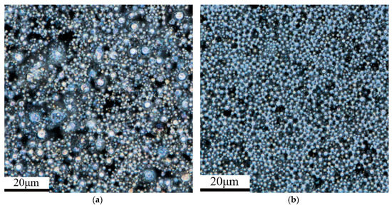
Figure 1.
The CLSM picture of (a) 400 and (b) 500 mesh zinc powder.
In this experiment, the water contact angles of samples with different formulations and film thicknesses were measured (Table 5) to understand the influence of zinc powder size and film thickness on the hydrophilicity. First, the water contact angles of Z4S and Z5S coatings were less than 90°, which shows that Z4S and Z5S coatings can be wetted by water. Second, when the film thickness was the same, the water contact angles of Z4S and Z5S coatings had a small difference, which shows that the zinc powder size has little effect on the hydrophilicity. Third, when the zinc powder size was constant, the apparent contact angle (θγ) gradually decreased as the film thickness increased. This is mainly due to the fact that the surface roughness of coatings increases as the film thickness increases, in the case where the θγ is less than 90°, eigen contact angle (θ) < 90° is known from the Wenzel equation [47] (cosθγ = γcosθ, where the γ is the ratio of the actual to the geometric solid-liquid interface contact area and is ≥1). Wenzel [48] pointed out that when the θ is less than 90°, the θγ decreases as the surface roughness increases.

Table 5.
Water contact angles of samples with different formulations and film thicknesses.
Considering the influence of film forming effect and hydrophilicity, the Z5S formulation was selected for further investigation of the composite coatings.
3.3. Basic Mechanical Properties of Micaceous Iron Oxide Anticorrosion Coatings
The basic mechanical properties of the micaceous iron oxide anticorrosion coatings are shown in Table 6. It can be found that the adhesion and impact strength of the coatings do not change and reach Grade 1 and 50 kg⋅cm, respectively. This shows that the added pigments and fillers and their contents do not affect the adhesion of the resin to the metal substrate and the enwrapping of the resin to the pigments and fillers. The paint can form a continuous film after being cured. Since the resin is bonded with the metal substrate by a chemical bond (Equation (3)), the coatings have good cohesiveness and flexibility.

Table 6.
Basic mechanical properties of micaceous iron oxide anticorrosion coatings.
From Table 6, it can be seen that the pencil hardness increases from 2H to 4H as the contents of micaceous iron oxide increase from 8% to 16%. This shows that the addition of micaceous iron oxide can indeed improve the scratch resistance of the coating but there is limit for the amount of micaceous iron oxide.
3.4. Anticorrosion Performance of Composite Coatings
3.4.1. Corrosion of Composite Coatings in Seawater
The AC impedance of the composite coatings immersed in seawater was measured at 1 h, 2 h, 4 h, 6 h and 8 h. The results for the Z5S + M16 coatings are shown in Figure 2 while the results of the other coatings are shown in Figure A1, Figure A2, Figure A3 and Figure A4
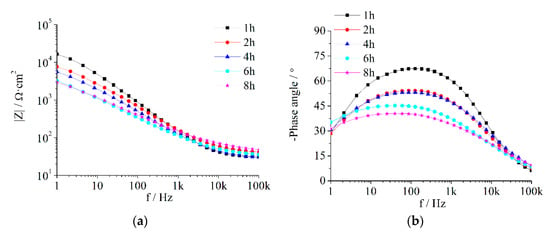
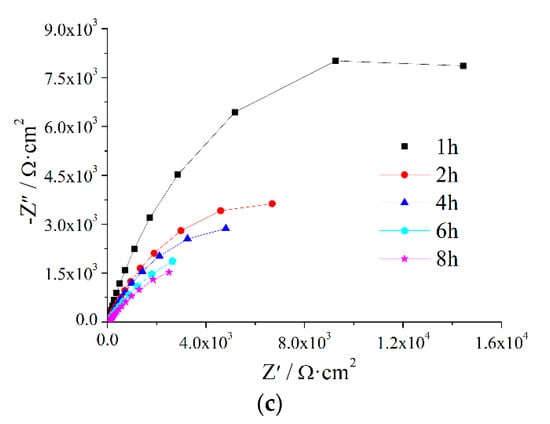
Figure 2.
EIS of Z5S + M16 immersed in seawater for different times.
Based on the Bode plot in Figure 2a,b, each |Z|-ƒ curve is basically a diagonal and there is only one peak on the negative phase angle-ƒ curve. It shows that the composite coatings always present the impedance spectrum of one time constant during the test period; in other words, the seawater does not penetrate the anticorrosion coating and reach the antirust coating over 8 h. Compared with some conventional coatings, such as waterborne modified epoxy [49] and polyurethane coating [50], the protection performance of the composite coatings prepared in this paper was better than that of these conventional coatings.
The Nyquist plot in Figure 2c indicates that the capacitive loop decreases with an extension of the immersion time. From the Bode plot in Figure 2, it can be seen that with the prolongation of immersion time, the low frequency impedance reduces and the |Z|-ƒ curve moves toward the low frequency direction, the phase angle curve descends and moves toward the high frequency direction. These show that Qc increases while Rc decreases as immersion time increases, it indicates that corrosive media penetrate gradually into the composite coating.
The measurement results in Figure 2 were analysed using the equivalent circuit R(QR) (Figure 3) in the ZSimpWin3.2.1 software and the fitted results are shown in Table 7. Qc gradually increases while dispersion coefficient (n) and Rc gradually decrease as immersion time is extended.

Figure 3.
Equivalent circuit used to fit the EIS data.

Table 7.
Electrochemical parameters of the equivalent circuit for micaceous iron oxide composite coatings immersed at different times in seawater.
3.4.2. The Protective Performance Evaluated by Coating Resistance
The values of Rc, which can evaluate the protective performance of the coatings, are extracted from Table 7 and immersion time is plotted on the horizontal axis while Rc is plotted on the vertical axis (Figure 4). Rc decreases with the prolonging of immersion time for each content of micaceous iron oxide. In the earlier stage of immersion, the coating porosity increases due to the penetration of water as well as aggressive ions, while Rc is inversely proportional to coating porosity, so Rc decreases with immersion time. At the same immersion time, the coatings with higher micaceous iron oxide content have larger Rc. This may be due to the fact that the defects in the coating, as well as the coating porosity, gradually decrease as the micaceous iron oxide content gradually increase.
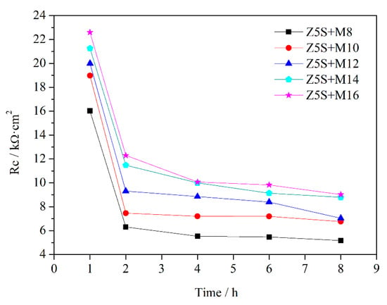
Figure 4.
The changes of Rc curves as a function of immersion time.
3.4.3. The Protective Performance Evaluated by Breakpoint Frequency
Since breakpoint frequency is related to the coating porosity or the coating defect area, the can be used to evaluate the protective properties of the coating [51,52]. Cao [51] and Haruyama [53] provided the breakpoint frequency formula without considering the dispersion effect. Liu [39] used the −45° phase angle at a high frequency to obtain an improved breakpoint frequency formula considering the dispersion effect. However, some research [51] has shown that the phase angle corresponding to the is no longer −45° for some coatings with the dispersion effect. It is similar to this investigation. Therefore, Liu’s formula is not suitable for this paper. Haruyama [53] proposed an extreme value method to calculate the breakpoint frequency. This method is still available in the presence of the dispersion effect [51]. Accordingly, this method was adopted to deduce the breakpoint frequency formula.
Taking into account Rs and the influence of the dispersion effect, the expression of the impedance corresponding to the equivalent circuit R(QR) shown in Figure 3 is
where Y0 is the constant of the constant-phase element (CPE), which is the value of Qc in Table 7 and ω is the angular frequency.
Therefore, is
The extreme value of should obey the following formula [53]:
That is
where is the characteristic angular frequency. The relationship between and is
The data in Table 7 are substituted into Equation (8) to obtain and then is substituted into Equation (9) to obtain . The breakpoint frequency calculated by the above mentioned equations was plotted with immersion time in Figure 5.
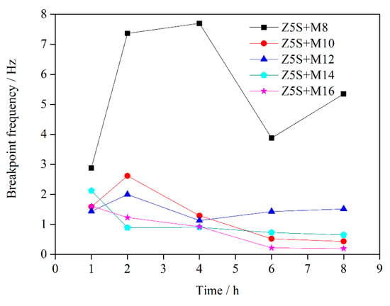
Figure 5.
The changes of curves as a function of immersion time.
The change range of with immersion time is larger when the micaceous iron oxide content is 8%. This is mainly due to the fact that micaceous iron oxide has a disorderly arrangement in the coating when the contents of micaceous iron oxide are relatively lower, as shown in Figure 6a. It affects the quantity and distribution of defects in the coating to some extent, leading to a larger difference in the quantity of defects in all directions of the coating. The relationship between and defect area () is , where K, A is coating area, d is coating thickness, is the dielectric constant of coating containing corrosive media, is the dielectric constant in vacuum, is electrochemical reaction resistance per unit area [52]. The A and the d are constant in this experiment. The increases while the decreases as corrosive media penetrate into the coating. This opposite effect can make the be regarded approximately as a constant. So is proportional to the . Therefore, shows sharp fluctuation with immersion time when the changes drastically with immersion time due to lower micaceous iron oxide content. The fluctuation of with immersion time is weakened as the contents of micaceous iron oxide increase. This is mainly due to the fact that with the increase of contents of micaceous iron oxide, its degree of disordered arrangement is reduced while the degree of ordered arrangement is increased (the micaceous iron oxide flakes are uniformly arranged in the coating and the flakes are alternately arranged in the cross-section direction of the coating, as shown in Figure 6b), which results in a reduction in the quantity of defects in the coating and an increase in the uniform of the distribution of defects in all directions of the coating. Therefore, the change range of the with immersion time decreases. Since is proportional to the , the fluctuation of decreases with immersion time. When the content of micaceous iron oxide reaches 16%, is small and the fluctuation of with immersion time is also small. It indicates that defects in the coating are few and their distribution is uniform as well as corrosive media diffusing slowly in the coating.
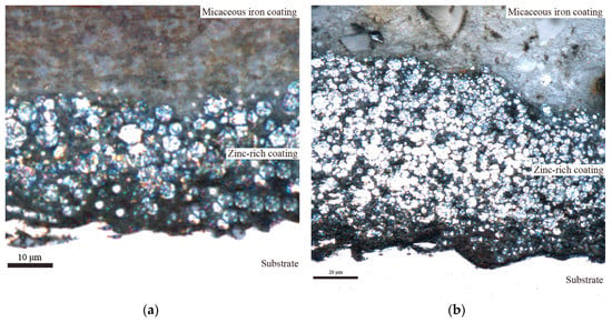
Figure 6.
The CLSM images of the cross section of the coatings (a) Z5S + M10, (b) Z5S + M14.
When the contents of micaceous iron oxide are 10% to 12%, both and firstly increase, then decrease and finally tends to be stable as immersion time extends. This may be due to the fact that when the contents of micaceous iron oxide are relatively lower, micaceous iron’s degree of ordered arrangement is not very high, which results in a certain amount of micaceous irons to be irregularly arranged, as shown in Figure 7. When corrosive media diffuse in the direction shown in Figure 7 as immersion time increases, begins to increase gradually. As corrosive media continue to diffuse along the path shown in Figure 7, some of micaceous iron oxides may be slightly rotated or moved so that defects in their vicinity are filled or disappeared. After defects are reduced or minified, corrosive media are transferred to a “labyrinth structure” composed of regularly arranged micaceous iron oxides, where the coating has fewer defects and corrosive media can only diffuse along a tortuous path, resulting in a slow diffusion rate. Therefore, it appears that the firstly increases, then decreases and finally tends to be stable.
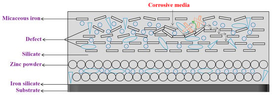
Figure 7.
The corrosive media penetration model of low micaceous iron oxide contents.
When the contents of micaceous iron oxide are 14% to 16%, trends initially decrease and subsequently become stable with immersion time. When the contents of micaceous iron oxide are relatively higher, micaceous iron’s degree of ordered arrangement is higher but in the orderly arranged micaceous iron oxide structure there are still some micaceous iron oxides that are in the special position, as shown in Figure 8. When corrosive media diffuse in the direction shown in Figure 8 as immersion time increases, which may cause micaceous iron oxide in the special position in the ordered structure to be slightly rotated or moved so that defects in their vicinity are filled or disappeared. After defects are reduced or minified, corrosive media are transferred to the orderly arranged micaceous iron oxide structure, where there are fewer defects and corrosive media can only slowly diffuse along the “labyrinth” formed by micaceous iron oxide. Therefore, as a whole, the shows the evolution trend of initial decrease and subsequent stability as immersion time is extended.
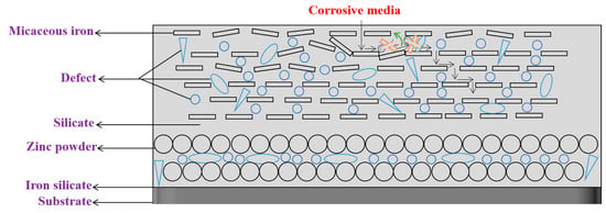
Figure 8.
The corrosive media penetration model of high micaceous iron oxide contents.
Based on the above analysis and the Figure 5, it could be concluded that the was less than 1.3 Hz from 2 h to 8 h when the micaceous iron oxide content exceeded 12%, indicating that the coating had a good protective structure.
4. Conclusions
In this paper, waterborne silicate zinc-rich antirust coatings, micaceous iron oxide anticorrosion coatings and composite coatings composed of antirust and anticorrosion ones were prepared and their properties were studied. For zinc-rich antirust coatings, when the particle size of zinc powder is constant, as the film thickness increases, the film forming effect becomes worse and the hydrophilicity of the coatings is enhanced. For micaceous iron oxide anticorrosion coatings, the adhesion and impact strength reached Grade 1 and 50 kg⋅cm, respectively, and the pencil hardness was up to 4H. These basic mechanical properties could meet the needs of the application on ships for anticorrosion coatings. Only one-time constant existed in the EIS results during the test period, which means that the composite coatings have good protection performance. The formula for breakpoint frequency, considering the dispersion effect, was deduced and used to evaluate the anticorrosive performance. It was found that the fluctuation of breakpoint frequency with immersion time was weakened as the content of micaceous iron oxide increased. Based on the relationship between breakpoint frequency and defect, different penetration models of corrosive media were proposed for the coatings with low or high contents of micaceous iron oxide.
Author Contributions
Conceptualization, X.Z., Y.Q. and Z.Z.; Methodology, X.Z., Y.Q. and Z.Z.; Software, Z.L.; Validation, K.L.; Formal Analysis, X.Z. and Z.Z.; Investigation, X.Z. and Z.Z.; Resources, Y.Q. and Z.Z.; Data Curation, X.Z.; Writing—Original Draft Preparation, X.Z.; Writing—Review and Editing, X.Z., Z.Z. and Y.Q.; Visualization, X.Z., K.L. and Z.L.; Supervision, Z.Z. and Y.Q.; Project Administration, Z.Z. and Y.Q.; Funding Acquisition, Z.Z. and Y.Q.
Funding
This research was funded by Project of Equipment Pre-research Field Fund, grant number 61409220304 and Equipment Pre-research Sharing Technology Project, grant number 41404010306 and 41423060314.
Conflicts of Interest
The authors declare no conflict of interest.
Appendix A
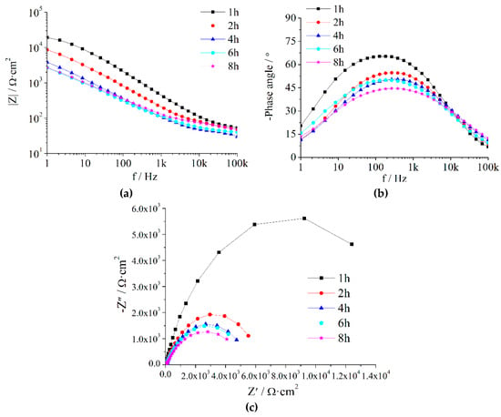
Figure A1.
EIS of Z5S + M8 immersed in seawater for different times.
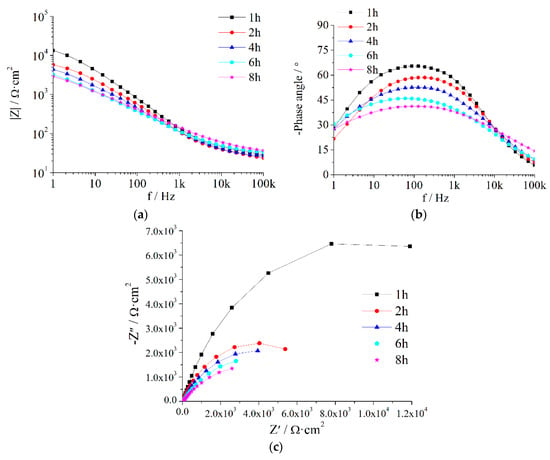
Figure A2.
EIS of Z5S + M10 immersed in seawater for different times.
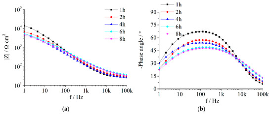
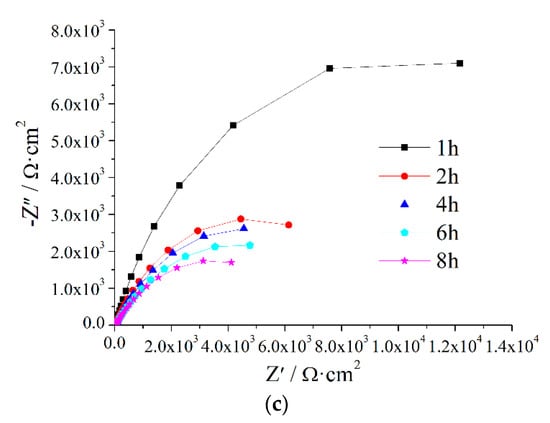
Figure A3.
EIS of Z5S + M12 immersed in seawater for different times.
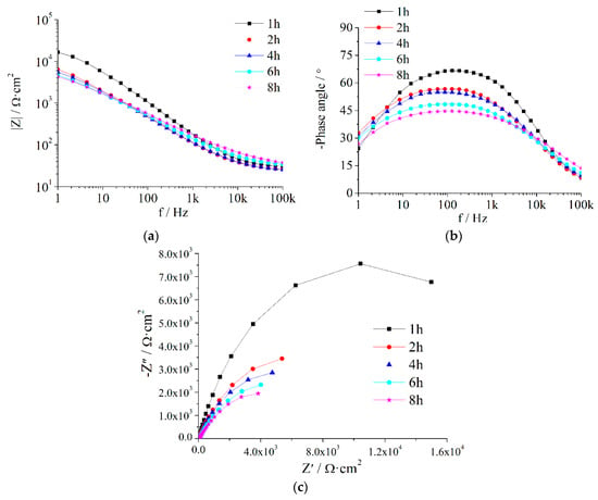
Figure A4.
EIS of Z5S + M14 immersed in seawater for different times.
References
- Wang, G.P. Marine Coating and Coating Technology, 2nd ed.; Chemical Industry Press: Beijing, China, 2006. [Google Scholar]
- Wang, N.; Cheng, K.Q.; Zhang, J.; Zhang, D.; Kang, P. Method for preparing polyaniline modified mesoporous molecular sieve anticorrosion coating. CN Patent 201210109355.5, 22 August 2012. [Google Scholar]
- Wang, N.; Wu, Y.H.; Cheng, K.Q.; Zhang, J. Investigation on anticorrosion performance of polyaniline-mesoporous MCM-41 composites in new water-based epoxy coating. Mater. Corros. 2015, 65, 968–976. [Google Scholar] [CrossRef]
- Bagherzadeh, M.R.; Ghasemi, M.; Mahdavi, F.; Shariatpanahi, H. Investigation on anticorrosion performance of nano and micro polyaniline in new water-based epoxy coating. Prog. Org. Coat. 2011, 72, 348–352. [Google Scholar] [CrossRef]
- Bagherzadeh, M.R.; Mahdavi, F.; Ghasemi, M.; Shariatpanahi, H.; Faridi, H.R. Using nanoemeraldine salt-polyaniline for preparation of a new anticorrosive water-based epoxy coating. Prog. Org. Coat. 2010, 68, 319–322. [Google Scholar] [CrossRef]
- Wang, Z.; Han, E.; Liu, F.; Qian, Z.; Zhu, L. Waterborne epoxy nanocoatings modified by nanoemulsions and nanoparticles. J. Mater. Sci. Technol. 2014, 30, 1036–1042. [Google Scholar] [CrossRef]
- Liu, J.H.; Zhan, Z.W.; L, S.M.; Yu, M. Corrosion resistance of waterborne epoxy coating pigmented by nano-sized aluminium powder on steel. J. Cent. South Univ. Technol. 2012, 19, 46–54. [Google Scholar] [CrossRef]
- Jiang, C. A waterborne metal anticorrosion coating. CN Patent 201410488980.4, 25 February 2015. [Google Scholar]
- Yao, Z.J.; Li, L.; Zhou, J.T.; Li, T.M.; Liu, P.J. Marine anticorrosion coating. CN Patent 201410337820.X, 8 October 2014. [Google Scholar]
- Xu, J.; Rong, X.; Chi, T.; Ming, W.; Wang, Y.; Yang, D.; Qiu, F. Preparation, characterization of UV-Curable Waterborne Polyurethane-Acrylate and the application in metal iron surface protection. J. Appl. Polym. Sci. 2014, 130, 3142–3152. [Google Scholar] [CrossRef]
- Ding, Y.S.; Ding, Y.Q.; Fang, H.G.; Yang, S.Z. An ultraviolet curing waterborne epoxy-polyurethane-acrylate copolymer resin-based anticorrosion paint and preparation method. CN Patent 201410275754.8, 10 September 2014. [Google Scholar]
- Rashvand, M.; Ranjbar, Z. Effect of nano-ZnO particles on the corrosion resistance of polyurethane-based waterborne coatings immersed in sodium chloride solution via EIS technique. Prog. Org. Coat. 2013, 76, 1413–1417. [Google Scholar] [CrossRef]
- Christopher, G.; Kulandainathan, M.A.; Harichandran, G. Highly dispersive waterborne polyurethane/ZnO nanocomposites for corrosion protection. J. Coat. Technol. Res. 2015, 12, 657–667. [Google Scholar] [CrossRef]
- Rahman, O.U.; Kashif, M.; Ahmad, S. Nanoferrite dispersed waterborne epoxy-acrylate: Anticorrosive nanocomposite coatings. Prog. Org. Coat. 2015, 80, 77–86. [Google Scholar] [CrossRef]
- Lin, L.; Xu, J. Study on Synthesis of nano-SiO2/polyacrylate compound antirust emulsion. Paint Coat. Ind. 2014, 44, 19–22. [Google Scholar]
- Lewis, O.D.; Critchlow, G.W.; Wilcox, G.D.; Dezeeuw, A.; Sander, J. A study of the corrosion resistance of a waterborne acrylic coating modified with nano-sized titanium dioxide. Prog. Org. Coat. 2012, 73, 88–94. [Google Scholar] [CrossRef]
- Li, J.; Ecco, L.; Delmas, G.; Whitehouse, N.; Pan, J. In-Situ AFM and EIS Study of waterborne acrylic latex coatings for corrosion protection of carbon steel. J. Electrochem. Soc. 2015, 162, C55–C63. [Google Scholar] [CrossRef]
- Sayyedan, F.S.; Enayati, M.H. On structure and oxidation behaviour of non-stoichiometric amorphous aluminium phosphate coating. Surf. Eng. 2019, 35, 670–676. [Google Scholar] [CrossRef]
- Mokabber, T.; Zhou, Q.; Vakis, A.I.; van Rijn, P.; Pei, Y.T. Mechanical and biological properties of electrodeposited calcium phosphate coatings. Mater. Sci. Eng. C Mater. Biol. Appl. 2019, 100, 475–484. [Google Scholar] [CrossRef] [PubMed]
- Castro, Y.; Duran, A. Control of degradation rate of Mg alloys using silica sol-gel coatings for biodegradable implant materials. J. Sol-gel Sci. Technol. 2019, 90, 198–208. [Google Scholar] [CrossRef]
- Guo, L.L.; Tao, X.; Gong, Z.; Guo, A.R.; Du, H.Y.; Liu, J.C. Preparation of MoSi2-SiC-Al2O3-SiO2 coating on mullite fibrous insulation with silica sol as binder by non-firing process. Ceram. Int. 2019, 45, 2602–2611. [Google Scholar] [CrossRef]
- Cheng, L.H.; Liu, C.L.; Han, D.J.; Ma, S.H.; Guo, W.H.; Cai, H.F.; Wang, X.H. Effect of graphene on corrosion resistance of waterborne inorganic zinc-rich coatings. J. Alloy. Compd. 2019, 774, 255–264. [Google Scholar] [CrossRef]
- Jolin, W.C.; Oster, C.; Kaminski, M.D. Silicate coating to prevent leaching from radiolabeled surrogate far-field fallout in aqueous environments. Chemosphere 2019, 222, 106–113. [Google Scholar] [CrossRef]
- Zhao, X.; Zhang, Z.Z.; Zhang, J.T.; Ding, G.Q. Research and development trend of environmentally friendly anticorrosive and antifouling coatings for hulls. Shanghai Coat. 2017, 55, 24–28. (In Chinese) [Google Scholar]
- Giúdice, C.A.; Benítez, J.C. Optimising the corrosion protective abilities of lamellar micaceous iron oxide containing primers. Anticorros. Methods Mater. 2000, 47, 226–232. [Google Scholar] [CrossRef]
- Sørensen, P.A.; Kiil, S.; Dam-Johansen, K.; Weinell, C.E. Anticorrosive coatings: A review. J. Coat. Technol. Res. 2009, 6, 135–176. [Google Scholar] [CrossRef]
- Nikravesh, B.; Ramezanzadeh, B.; Sarabi, A.A.; Kasiriha, S.M. Evaluation of the corrosion resistance of an epoxy-polyamide coating containing different ratios of micaceous iron oxide/Al pigments. Corros. Sci. 2011, 53, 1592–1603. [Google Scholar] [CrossRef]
- Wang, G.; Yang, J. Influences of glass flakes on fire protection and water resistance of waterborne intumescent fire resistive coating for steel structure. Prog. Org. Coat. 2011, 70, 150–156. [Google Scholar] [CrossRef]
- Yang, C.; Smyrl, W.H.; Cussler, E.L. Flake alignment in composite coatings. J. Membr. Sci. 2004, 231, 1–12. [Google Scholar] [CrossRef]
- Naser Kakaei, M.; Danaee, I.; Zaarei, D. Evaluation of cathodic protection behavior of waterborne inorganic zinc-rich silicates containing various contents of MIO pigments. Anticorros. Methods Mater. 2013, 60, 37–44. [Google Scholar] [CrossRef]
- Castela, A.S.; Simões, A.M. An impedance model for the estimation of water absorption in organic coatings. Part II: A complex equation of mixture. Corros. Sci. 2003, 45, 1647–1660. [Google Scholar] [CrossRef]
- Deflorian, F.; Fedrizzi, L.; Bonora, P.L. Influence of the photo-oxidative degradation on the water barrier and corrosion protection properties of polyester paints. Corros. Sci. 1996, 38, 1697–1708. [Google Scholar] [CrossRef]
- Barranco, V.; Carpentier, J.; Grundmeier, G. Correlation of morphology and barrier properties of thin microwave plasma polymer films on metal substrate. Electrochim. Acta 2004, 49, 1999–2013. [Google Scholar] [CrossRef]
- Brasher, D.M.; Kingsbury, A.H. Electrical measurements in the study of immersed paint coatings on metal. I. Comparison between capacitance and gravimetric methods of estimating water uptake. J. Chem. Technol. Biotechnol. 2010, 4, 62–72. [Google Scholar] [CrossRef]
- Castela, A.S.; Simões, A.M. An impedance model for the estimation of water absorption in organic coatings. Part I: A linear dielectric mixture equation. Corros. Sci. 2003, 45, 1631–1646. [Google Scholar] [CrossRef]
- Castela, A.S.; Simões, A.M. Assessment of water uptake in coil coatings by capacitance measurements. Prog. Org. Coat. 2003, 46, 55–61. [Google Scholar] [CrossRef]
- Neshati, J.; Fardi, M.R. Evaluation and investigation of surface treatment of industrial coatings by impedance spectroscopy. Surf. Eng. 2013, 20, 299–303. [Google Scholar] [CrossRef]
- Sykes, J.M. A variant of the Brasher–Kingsbury equation. Corros. Sci. 2004, 46, 515–517. [Google Scholar] [CrossRef]
- Liu, L.; Hu, J.M.; Zhang, J.Q.; Cao, C.N. Evaluation of protectiveness of organic coatings by means of high-frequency EIS measurement. Corros. Sci. Prot. Technol. 2010, 22, 325–328. [Google Scholar]
- Wang, P.; Yang, Q.; Cheng, X.R. Study on the curing mechanism of sodium silicate inorganic zinc-rich coating. Appl. Chem. Ind. 2007, 36, 1076–1080. [Google Scholar]
- Peng, G.Y. Preparation and Properties of Waterborne Inorganic Coatings with Potassium Silicate/Silica Sol as Film-Forming Substance. Master’s Thesis, South China University of Technology, Guangzhou, China, 2012. [Google Scholar]
- Zhou, C.J. Preparation of Silicate Waterborne Inorganic Zinc-Rich Anticorrosion Coatings and Studies on Its Performance. Master’s Thesis, Shenyang University of Technology, Shenyang, China, 2014. [Google Scholar]
- GB/T 1720-1979 Method of Test for Adhesion of Paint Films; China Petroleum and Chemical Industry Federation: Beijing, China, 1980.
- GB/T 6739-2006 Paints and Varnishes-Determination of Film Hardness by Pencil Test; China Petroleum and Chemical Industry Federation: Beijing, China, 2007.
- GB/T 1732-1993 Determination of Impact Resistance of Film; China Petroleum and Chemical Industry Federation: Beijing, China, 1993.
- Qi, Y.H.; Zhang, Z.P.; Miao, M.; Zhang, X.Z. Studies on estimating methods of polarization performance for coated steel in seawater. Mater. Sci. Forum 2010, 654–656, 2418–2421. [Google Scholar] [CrossRef]
- Wenzel, R.N. Resistance of solid surfaces to wetting by water. Ind. Eng. Chem. 1936, 28, 988–994. [Google Scholar] [CrossRef]
- Jiang, L.; Feng, L. Bionic Intelligent Nano Interface Material; Chemical Industry Press: Beijing, China, 2007. [Google Scholar]
- Ding, J.H.; Liu, S.; Gu, L.; Zhao, H.C.; Yu, H.B. Corrosion resistance of epoxy phosphate/waterborne epoxy coatings on steel. China Surf. Eng. 2015, 28, 126–131. (In Chinese) [Google Scholar]
- Li, Y.; Yang, Z.; Qiu, H.; Dai, Y.; Zheng, Q.; Li, J.; Yang, J. Self-aligned graphene as anticorrosive barrier in waterborne polyurethane composite coatings. J. Mater. Chem. A 2014, 2, 14139–14145. [Google Scholar] [CrossRef]
- Cao, C.N.; Zhang, J.Q. Introduction to Electrochemical Impedance Spectroscopy; Science Press: Beijing, China, 2002. [Google Scholar]
- Liu, H.; Liang, F.; Zhang, J.; Cao, C.; Shuqin, X.U.; Lin, H.; Dong, J.; Cai, Z. Investigation of effect of aluminium powder on performance of epoxy coatings by breakpoint frequency method. Corros. Sci. Prot. Technol. 1992, 4, 144–149. [Google Scholar]
- Haruyama, S.; Asari, S.; Tsuru, T. Corrosion protection by organic coatings. Electrochem. Soc. 1987, 87, 197–207. [Google Scholar]
© 2019 by the authors. Licensee MDPI, Basel, Switzerland. This article is an open access article distributed under the terms and conditions of the Creative Commons Attribution (CC BY) license (http://creativecommons.org/licenses/by/4.0/).