Degradation Behaviour of Mg0.6Ca and Mg0.6Ca2Ag Alloys with Bioactive Plasma Electrolytic Oxidation Coatings


Abstract
1. Introduction
2. Materials and Methods
3. Results
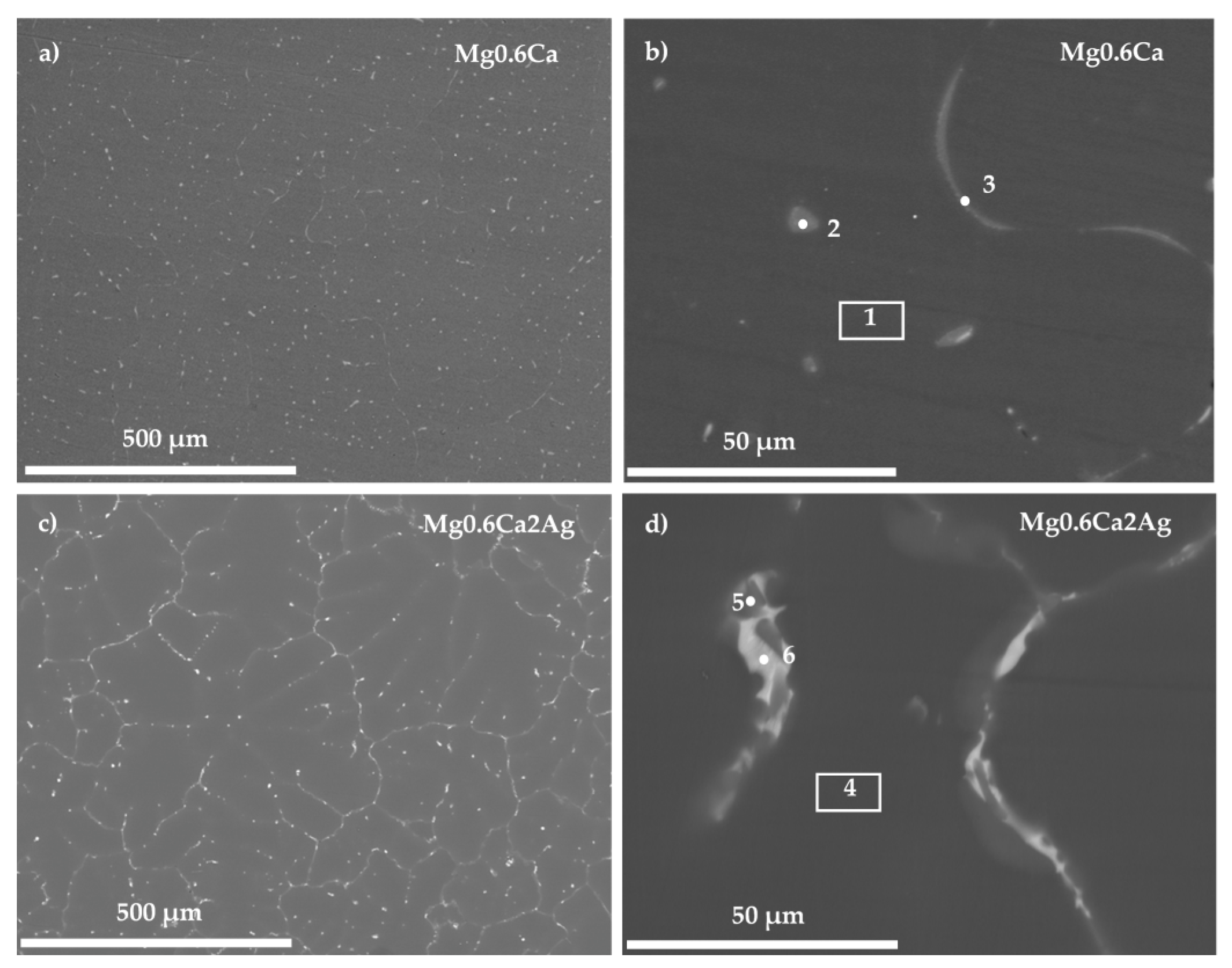
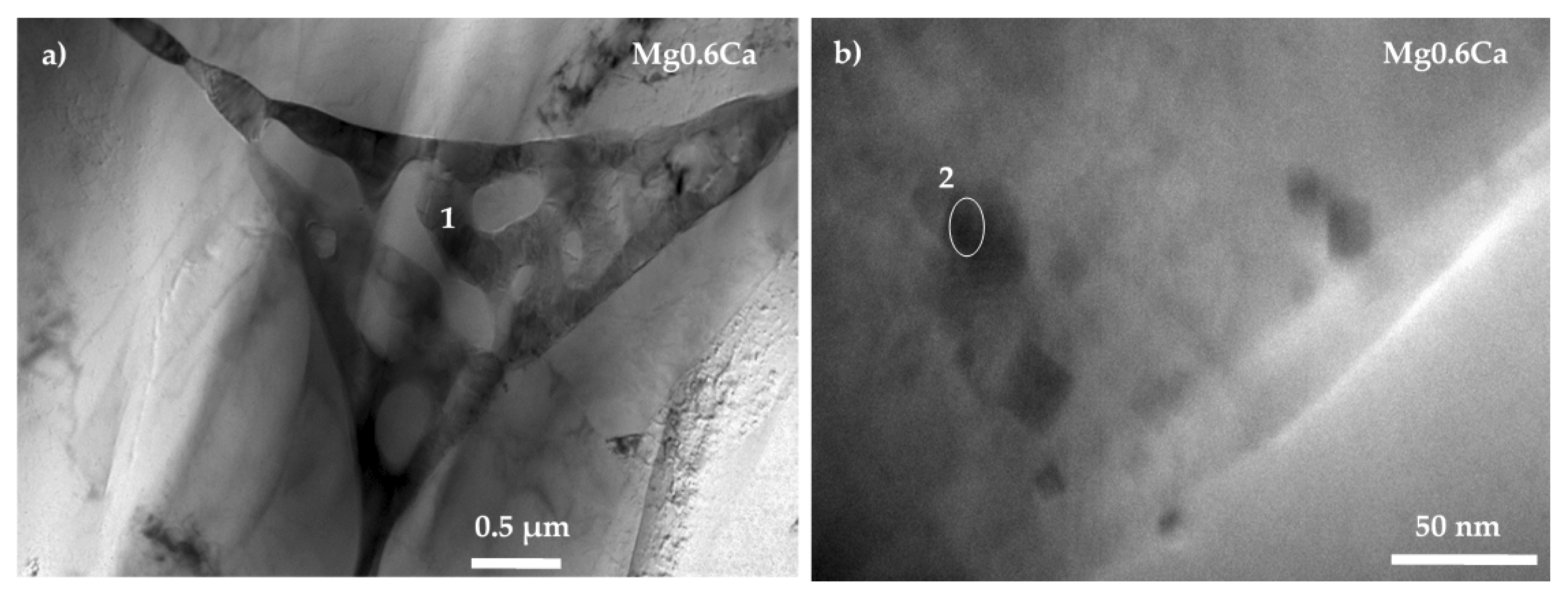
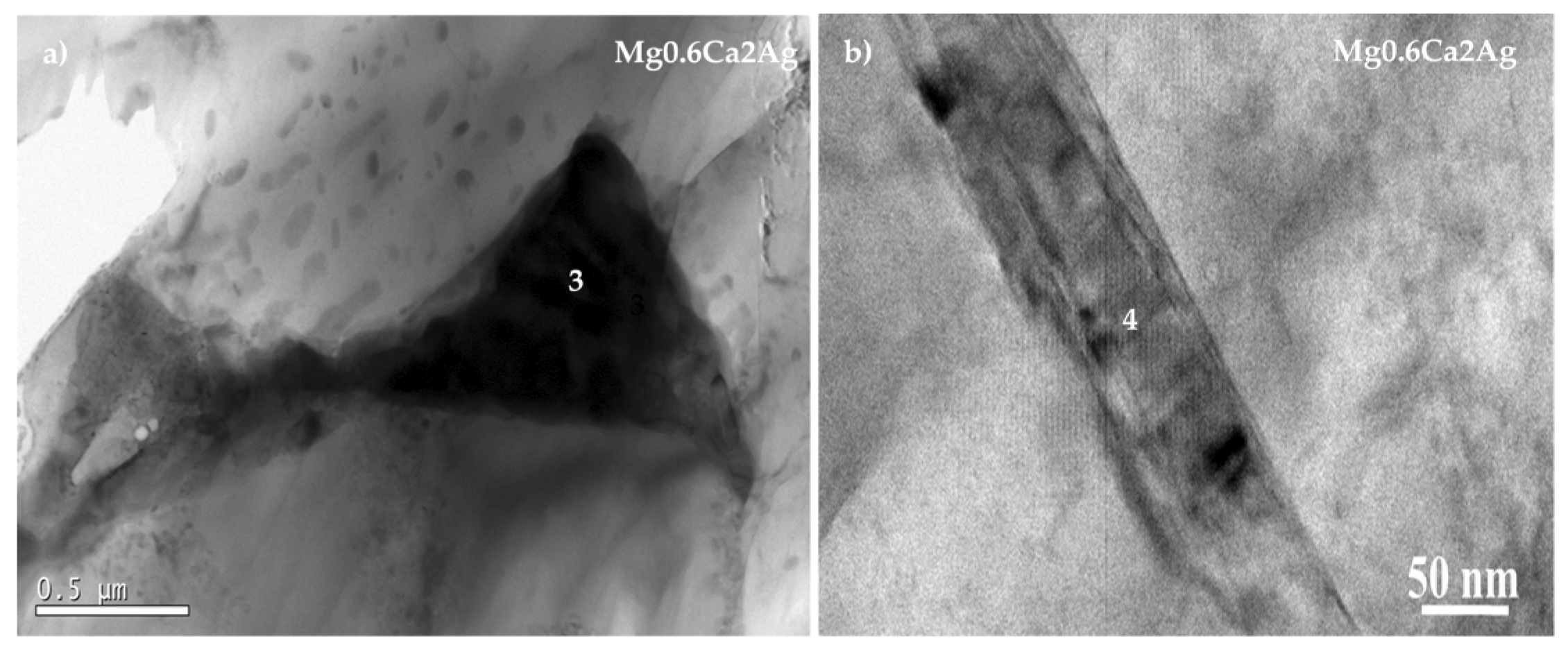
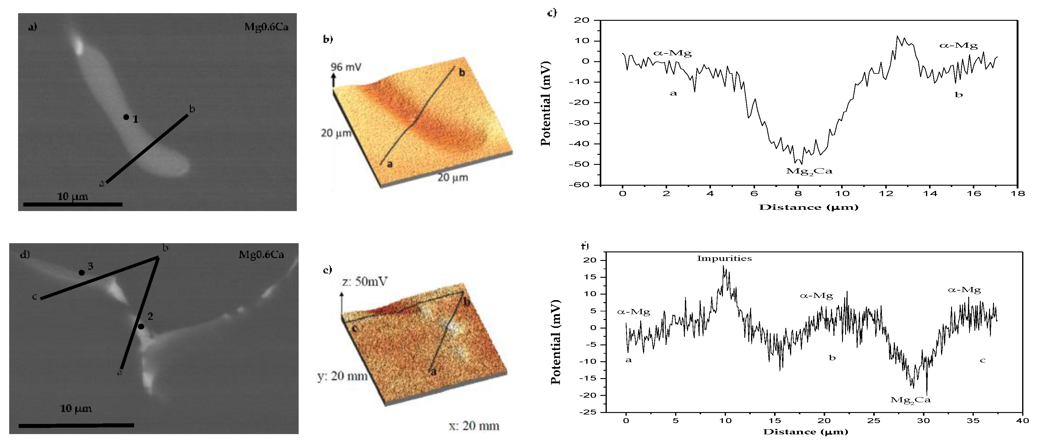
3.1. Characterisation
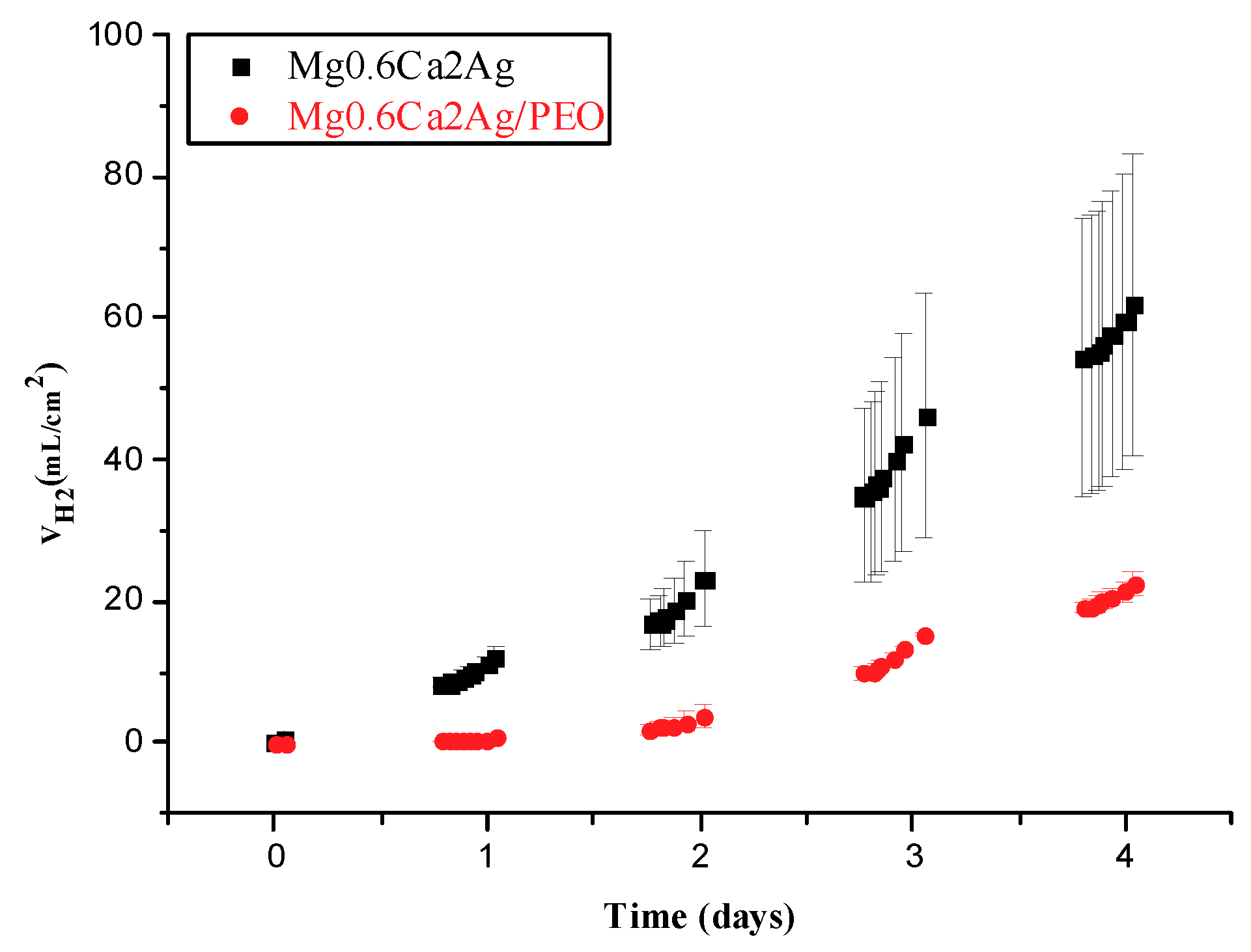
3.2. Hydrogen Evolution Measurement
3.3. Fluoride Release
4. Conclusions
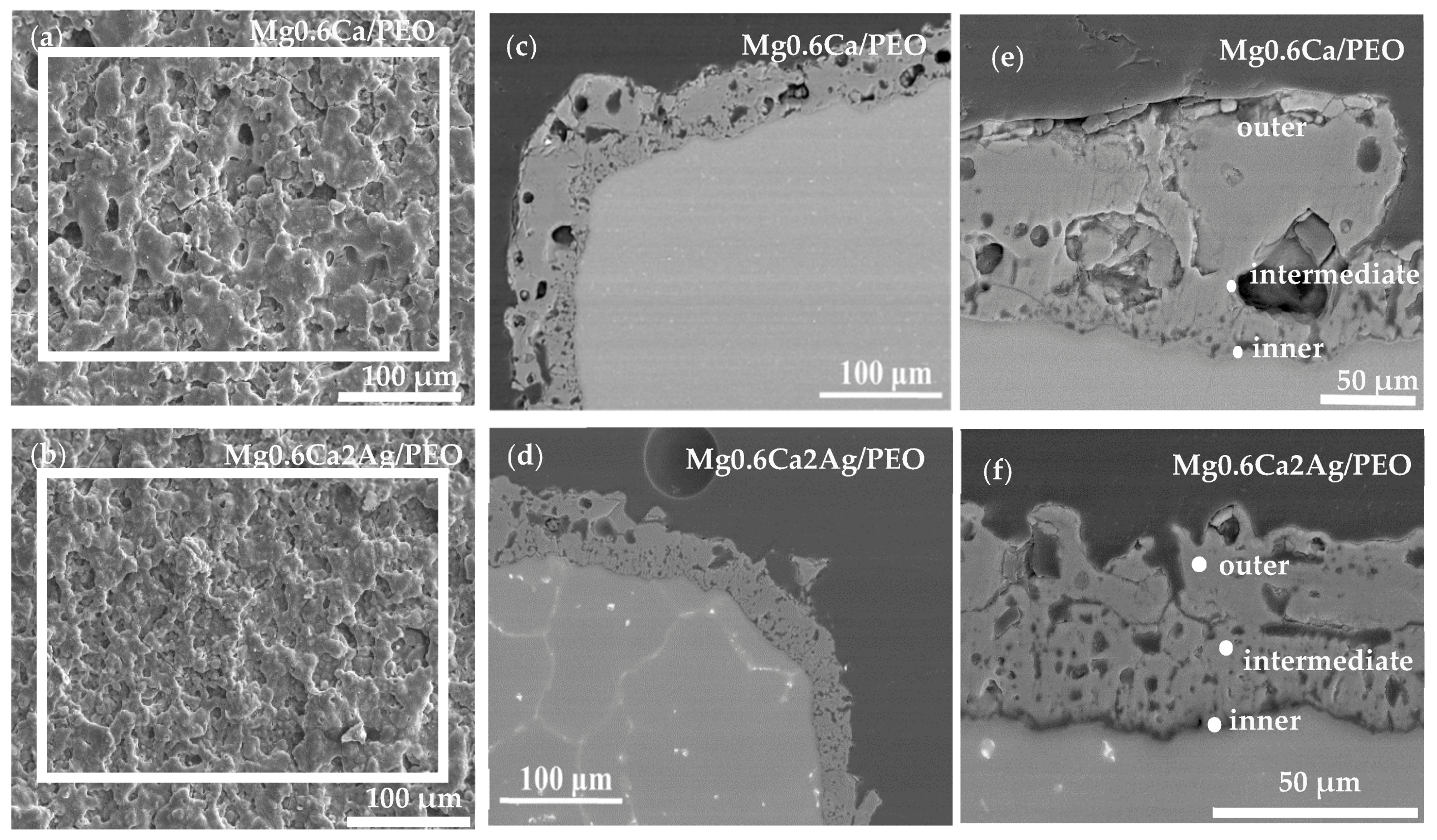
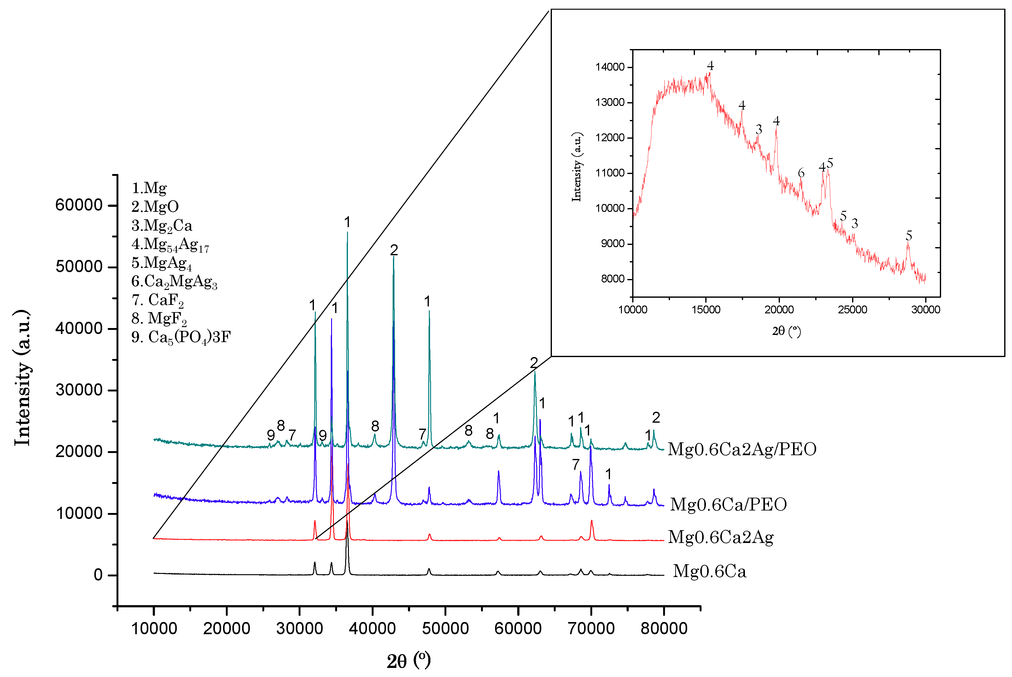
- PEO coatings of 32–35 μm thickness, containing bioactive calcium fluoride, magnesium fluoride and fluorapatite phases, were generated on Mg0.6Ca and Mg0.6Ca2Ag alloys for biomedical implant applications.
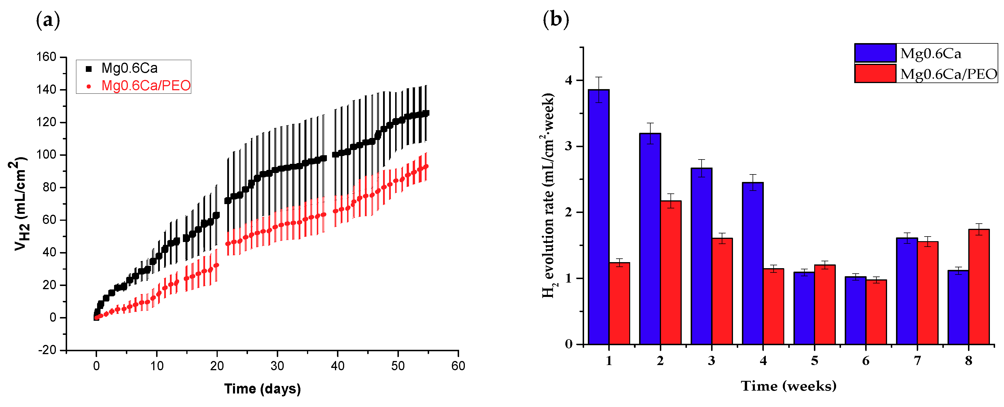
- The hydrogen evolution rate of PEO-coated Mg0.6Ca 3D prototypes evaluated during long-term immersion tests (up to 60 days), was 3.86 mL/cm2 week during the first month of immersion in SBF and 1.75 mL/cm2 week during the second month of immersion. The uncoated alloy generated two times more hydrogen in the first month of the test.
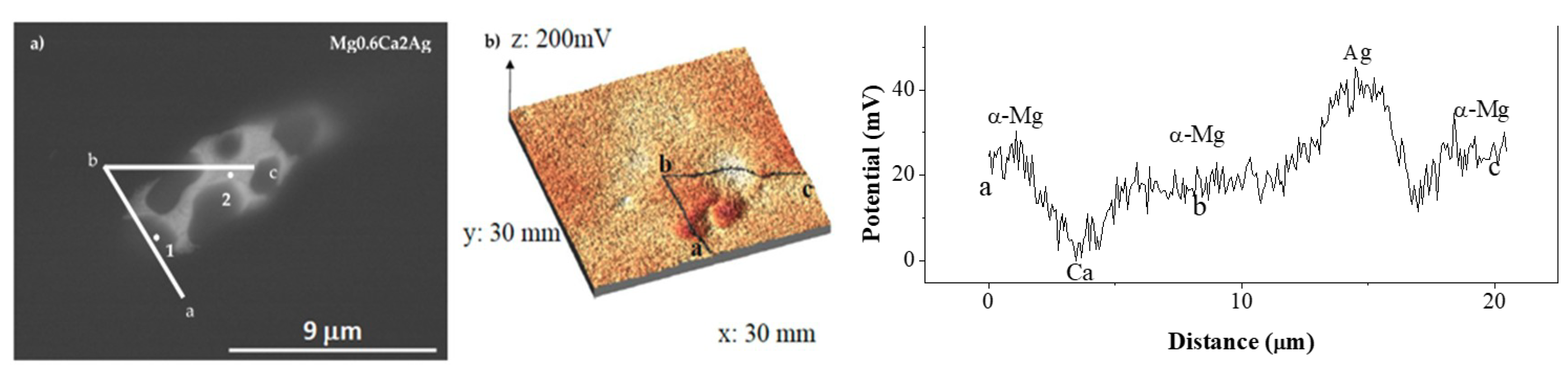
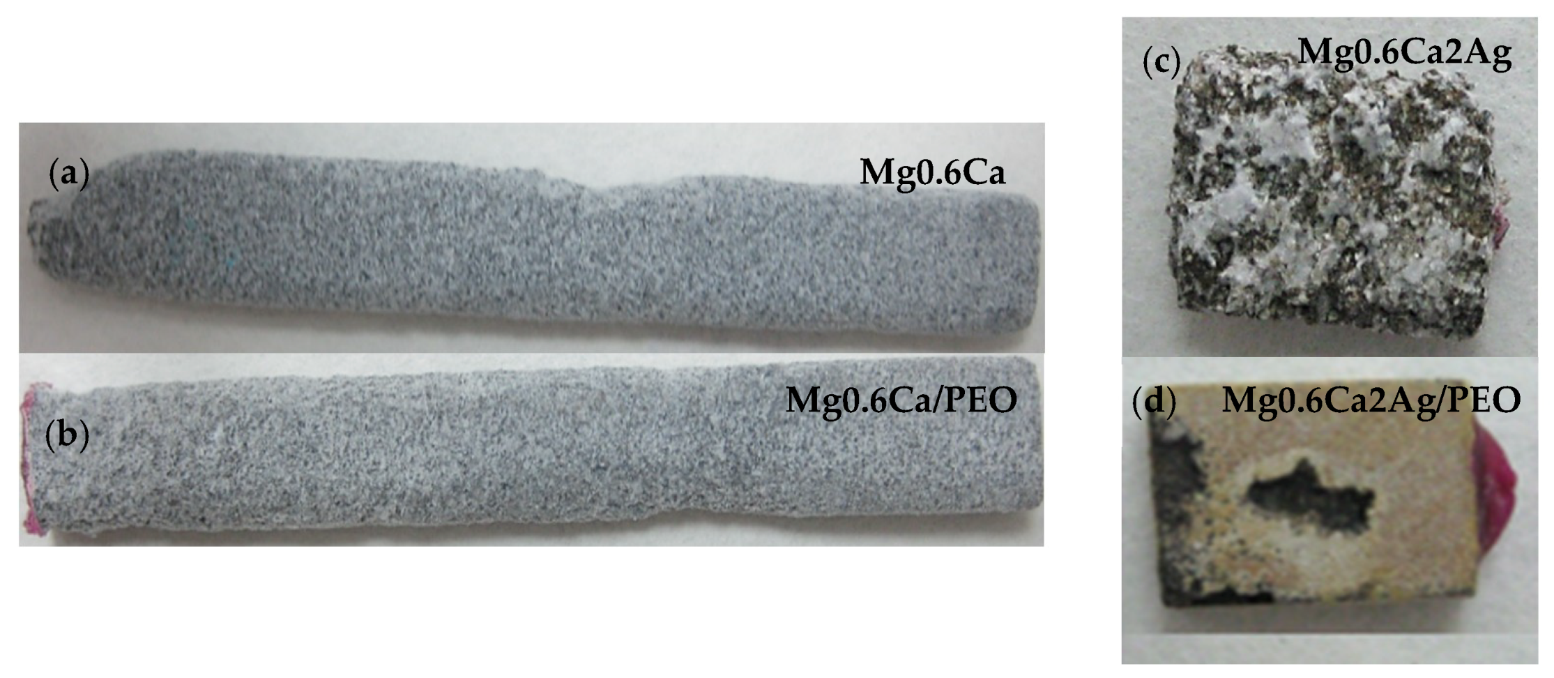
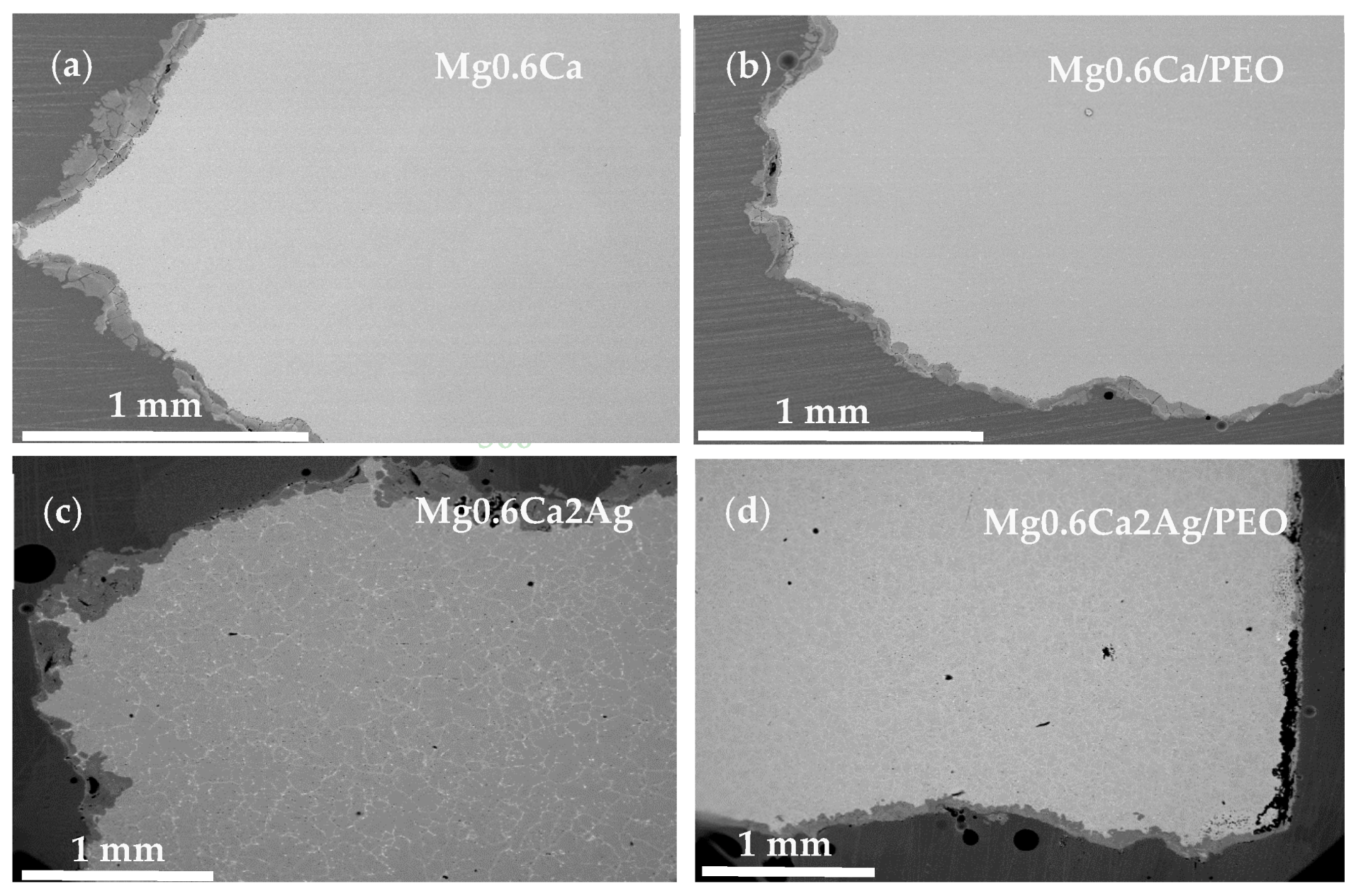
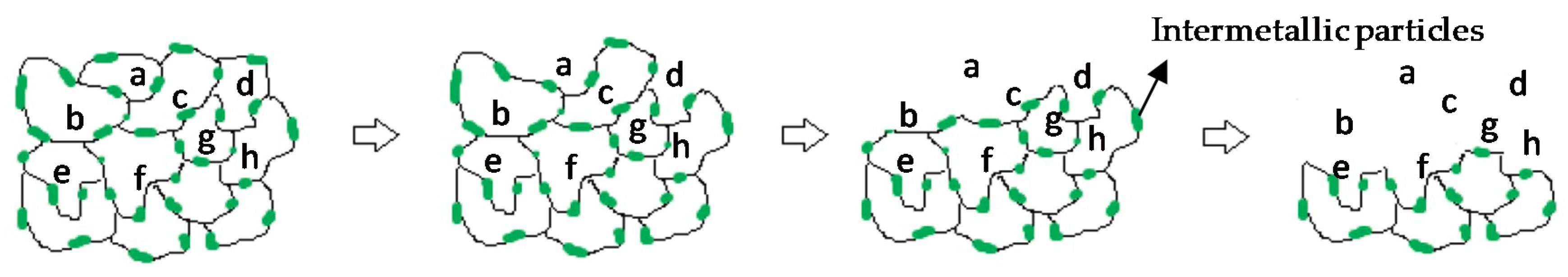
- The degradation mechanism during immersion of the studied materials corresponds to a generalized corrosion in both alloys. The Mg0.6Ca2Ag alloys degrade much faster than Mg0.6Ca due to the varied content of Ag and impurities in Mg–Ca–Ag intermetallic particles, which are mainly distributed along the grain boundaries; some of them acting as local anodes and causing the loss of the whole grain or clusters of grains. This also happens in Mg0.6Ca but to a much lesser extent, which leads to a slower corrosion process.
- The PEO coatings liberate fluoride ions during immersion in 0.9 M NaCl. The fluoride release is increased throughout 24 h of immersion time for Mg0.6Ca/PEO. The fluoride reserves of the coating have not been completely depleted in the course of the 24 h immersion.
Author Contributions
Funding
Acknowledgments
Conflicts of Interest
References
- Sanchez, A.H.M.; Luthringer, B.J.; Feyerabend, F.; Willumeit, R. Mg and Mg alloys: How comparable are in vitro and in vivo corrosion rates? A review. Acta Biomater. 2014, 13, 16–31. [Google Scholar] [CrossRef] [PubMed]
- Ding, W. Opportunities and challenges for the biodegradable magnesium alloys as next-generation biomaterials. Regen. Biomater. 2016, 3, 79–86. [Google Scholar] [CrossRef] [PubMed]
- Antoniac, I.; Laptoiu, D. Magnesium alloys—Current orthopedic applications. Revista de Ortopedie si Traumatologie a Asociatiei de Ortopedie Româno-Italo-Spaniole 2010, 4, 79–88. [Google Scholar]
- Manivasagam, G.; Suwas, S. Biodegradable Mg and Mg based alloys for biomedical implants. Mater. Sci. Technol. 2014, 30, 515–520. [Google Scholar] [CrossRef]
- Staiger, M.P.; Pietak, A.M.; Huadmai, J.; Dias, G. Magnesium and its alloys as orthopedic biomaterials: A review. Biomaterials 2006, 27, 1728–1734. [Google Scholar] [CrossRef]
- Waizy, H.; Seitz, J.M.; Reifenrath, J.; Weizbauer, A.; Bach, F.W.; Meyer-Lindenberg, A.; Denkena, B.; Windhagen, H. Biodegradable magnesium implants for orthopedic applications. J. Mater. Sci. 2013, 48, 39–50. [Google Scholar] [CrossRef]
- Walker, J.; Shadanbaz, S.; Woodfield, T.B.F.; Staiger, M.P.; Dias, G.J. Magnesium biomaterials for orthopedic application: A review from a biological perspective. J. Biomed. Mater. Res. B 2014, 102, 1316–1331. [Google Scholar] [CrossRef]
- Feliu, S., Jr.; Pardo, A.; Merino, M.C.; Coy, A.E.; Viejo, F.; Arrabal, R. Correlation between the surface chemistry and the atmospheric corrosion of AZ31, AZ80 and AZ91D magnesium alloys. Appl. Surf. Sci. 2009, 255, 4102–4108. [Google Scholar] [CrossRef]
- Esmaily, M.; Svensson, J.E.; Fajardo, S.; Birbilis, N.; Frankel, G.S.; Virtanen, S.; Arrabal, R.; Thomas, S.; Johansson, L.G. Fundamentals and advances in magnesium alloy corrosion. Prog. Mater. Sci. 2017, 89, 92–193. [Google Scholar] [CrossRef]
- Pardo, A.; Merino, M.C.; Coy, A.E.; Viejo, F.; Arrabal, R.; Feliú, S., Jr. Influence of microstructure and composition on the corrosion behaviour of Mg/Al alloys in chloride media. Electrochim. Acta 2008, 53, 7890–7902. [Google Scholar] [CrossRef]
- Makar, G.L.; Kruger, J. Corrosion of magnesium. Int. Mater. Rev. 1993, 38, 138–153. [Google Scholar] [CrossRef]
- Chen, Y.; Xu, Z.; Smith, C.; Sankar, J. Recent advances on the development of magnesium alloys for biodegradable implants. Acta Biomater. 2014, 10, 4561–4573. [Google Scholar] [CrossRef]
- Radha, R.; Sreekanth, D. Insight of magnesium alloys and composites for orthopedic implant applications—A review. J. Magnes. Alloy. 2017, 5, 286–312. [Google Scholar] [CrossRef]
- Zhang, C.; Lin, J.; Liu, H. Magnesium-based biodegradable materials for biomedical applications. MRS Adv. 2018, 3, 2359–2364. [Google Scholar] [CrossRef]
- Gusieva, K.; Davies, C.H.J.; Scully, J.R.; Birbilis, N. Corrosion of magnesium alloys: The role of alloying. Int. Mater. Rev. 2015, 60, 169–194. [Google Scholar] [CrossRef]
- Tie, D.; Feyerabend, F.; Müller, W.-D.; Schade, R.; Liefeith, K.; Kainer, K.; Willumeit, R. Antibacterial biodegradable Mg-Ag alloys. Eur. Cells Mater. 2013, 25, 284–298. [Google Scholar] [CrossRef]
- Chen, Q.; Thouas, G.A. Metallic implant biomaterials. Mater. Sci. Eng. R. 2015, 87, 1–57. [Google Scholar] [CrossRef]
- Rad, H.R.B.; Idris, M.H.; Kadir, M.R.A.; Farahany, S. Microstructure analysis and corrosion behavior of biodegradable Mg-Ca implant alloys. Mater. Des. 2012, 33, 88–97. [Google Scholar] [CrossRef]
- Li, Z.; Gu, X.; Lou, S.; Zheng, Y. The development of binary Mg-Ca alloys for use as biodegradable materials within bone. Biomaterials 2008, 29, 1329–1344. [Google Scholar] [CrossRef]
- Salahshoor, M.; Guo, Y. Biodegradable orthopedic magnesium-calcium (MgCa) alloys, processing, and corrosion performance. Materials 2012, 5, 135–155. [Google Scholar] [CrossRef]
- Mohedano, M.; Arrabal, R.; Mingo, B.; Pardo, A.; Matykina, E. Role of particle type and concentration on characteristics of PEO coatings on AM50 magnesium alloy. Surf. Coat. Technol. 2018, 334, 328–335. [Google Scholar] [CrossRef]
- Yu, K.; Dai, Y.; Luo, Z.; Long, H.; Zeng, M.; Li, Z.; Zhu, J.; Cheng, L.; Zhang, Y.; Liu, H.; et al. In vitro and in vivo evaluation of novel biodegradable Mg-Ag-Y alloys for use as resorbable bone fixation implant. J. Biomed. Mater. Res. A 2018, 106, 2059–2069. [Google Scholar] [CrossRef] [PubMed]
- Gopi, D.; Shinyjoy, E.; Kavitha, L. Synthesis and spectral characterization of silver/magnesium co-substituted hydroxyapatite for biomedical applications. Spectrochim. Acta Part A 2014, 127, 286–291. [Google Scholar] [CrossRef] [PubMed]
- Mohedano, M.; Lu, X.; Matykina, E.; Blawert, C.; Arrabal, R.; Zheludkevich, M. Plasma electrolytic oxidation (PEO) of metals and alloys. Encycl. Interfacial Chem. 2018, 423–438. [Google Scholar]
- Mohedano, M.; Luthringer, B.J.C.; Mingo, B.; Feyerabend, F.; Arrabal, R.; Sanchez-Egido, P.J.; Blawert, C.; Willumeit-Römer, R.; Zheludkevich, M.L.; Matykina, E. Bioactive plasma electrolytic oxidation coatings on Mg-Ca alloy to control degradation behavior. Surf. Coat. Technol. 2017, 315, 454–467. [Google Scholar] [CrossRef]
- Gu, X.; Li, N.; Zhou, W.; Zheng, Y.; Zhao, X.; Cai, Q.; Ruan, L. Corrosion resistance and surface biocompatibility of a microarc oxidation coating on a Mg-Ca alloy. Acta Biomater. 2011, 7, 1880–1889. [Google Scholar] [CrossRef]
- Jugdaohsingh, R. Silicon and bone health. J. Nutr. Health Aging 2007, 11, 99–110. [Google Scholar]
- Pan, Y.; Chen, C.; Feng, R.; Cui, H.; Gong, B.; Zheng, T.; Ji, Y. Effect of calcium on the microstructure and corrosion behavior of microarc oxidized Mg-xCa alloys. Biointerphases 2018, 13, 011003. [Google Scholar] [CrossRef]
- Narayanan, T.S.; Park, I.S.; Lee, M.H. Strategies to improve the corrosion resistance of microarc oxidation (MAO) coated magnesium alloys for degradable implants: Prospects and challenges. Prog. Mater. Sci. 2014, 60, 1–71. [Google Scholar] [CrossRef]
- Kim, E.-J.; Bu, S.-Y.; Sung, M.-K.; Choi, M.-K. Effects of silicon on osteoblast activity and bone mineralization of MC3T3-E1 cells. Biol. Trace Elem. Res. 2013, 152, 105–112. [Google Scholar] [CrossRef]
- Salahshoor, M.; Guo, Y.B. Biodegradation control of magnesium-calcium biomaterial via adjusting surface integrity by synergistic cutting-burnishing. Procedia CIRP 2014, 13, 143–149. [Google Scholar] [CrossRef]
- Kirkland, N.T.; Birbilis, N.; Walker, J.; Woodfield, T.; Dias, G.J.; Staiger, M.P. In-vitro dissolution of magnesium-calcium binary alloys: Clarifying the unique role of calcium additions in bioresorbable magnesium implant alloys. J. Biomed. Mater. Res. Part B 2010, 95, 91–100. [Google Scholar] [CrossRef]
- Bita, A.I.; Antoniac, A.; Cotrut, C.; Vasile, E.; Ciuca, I.; Niculescu, M.; Antoniac, I. In vitro degradation and corrosion evaluation of Mg-Ca alloys for biomedical applications. J. Optoelectron. Adv. Mater. 2016, 18, 394–398. [Google Scholar]
- Deng, M.; Höche, D.; Lamaka, S.V.; Snihirova, D.; Zheludkevich, M.L. Mg-Ca binary alloys as anodes for primary Mg-air batteries. J. Power Sources 2018, 396, 109–118. [Google Scholar] [CrossRef]
- Wang, H.; Lou, Y.; Northwood, D.O. Synthesis of Ag nanoparticles by hydrolysis of Mg-Ag intermetallic compounds. J. Mater. Process. Technol. 2008, 204, 327–330. [Google Scholar] [CrossRef]
- Du, J.; Zhang, A.; Guo, Z.; Yang, M.; Li, M.; Xiong, S. Atomic cluster structures, phase stability and physicochemical properties of binary Mg-X (X = Ag, Al, Ba, Ca, Gd, Sn, Y and Zn) alloys from ab-initio calculations. Intermetallics 2018, 95, 119–129. [Google Scholar] [CrossRef]
- Bakhsheshi-Rad, H.; Abdul-Kadir, M.; Idris, M.; Farahany, S. Relationship between the corrosion behavior and the thermal characteristics and microstructure of Mg-0.5Ca-xZn alloys. Corros. Sci. 2012, 64, 184–197. [Google Scholar] [CrossRef]
- Yang, J.; Peng, J.; Nyberg, E.A.; Pan, F.-S. Effect of Ca addition on the corrosion behavior of Mg-Al-Mn alloy. Appl. Surf. Sci. 2016, 369, 92–100. [Google Scholar] [CrossRef]
- Ben-Hamu, G.; Eliezer, D.; Kaya, A.; Na, Y.; Shin, K. Microstructure and corrosion behavior of Mg-Zn-Ag alloys. Mater. Sci. Eng. A 2006, 435–436, 579–587. [Google Scholar] [CrossRef]
- Yerokhin, A.; Nie, X.; Leyland, A.; Matthews, A.; Dowey, S. Plasma electrolysis for surface engineering. Surf. Coat. Technol. 1999, 122, 73–93. [Google Scholar] [CrossRef]
- Scapin, M.A.; Guilhen, S.N.; Cotrim, M.E.; Pires, M.A.F. Determination of Ca/P molar ratio in hydroxyapatite (HA) by X-ray fluorescence technique. Proceedings of International Nuclear Atlantic Conference Brazilian Nuclear Program State Policy for A Sustainable World, Sao Paulo, Brazil, 4–9 October 2015. [Google Scholar]
- Mohedano, M.; Matykina, E.; Arrabal, R.; Pardo, A.; Merino, M. Metal release from ceramic coatings for dental implants. Dent. Mater. 2014, 30, 28–40. [Google Scholar] [CrossRef] [PubMed]
- Laws, K.J.; Shamlaye, K.F.; Granata, D.; Koloadin, L.S.; Löffler, J.F. Electron-band theory inspired design of magnesium-precious metal bulk metallic glasses with high thermal stability and extended ductility. Sci. Rep. 2017, 7, 3400. [Google Scholar] [CrossRef] [PubMed]
- Matykina, E.; Garcia, I.; Arrabal, R.; Mohedano, M.; Mingo, B.; Sancho, J.; Merino, M.; Pardo, A. Role of PEO coatings in long-term biodegradation of a Mg alloy. Appl. Surf. Sci. 2016, 389, 810–823. [Google Scholar] [CrossRef]
- Gao, Y.; Yerokhin, A.; Matthews, A. DC plasma electrolytic oxidation of biodegradable cp-Mg: In-vitro corrosion studies. Surf. Coat. Technol. 2013, 234, 132–142. [Google Scholar] [CrossRef]
- Arrabal, R.; Matykina, E.; Viejo, F.; Skeldon, P.; Thompson, G. Corrosion resistance of WE43 and AZ91D magnesium alloys with phosphate PEO coatings. Corros. Sci. 2008, 50, 1744–1752. [Google Scholar] [CrossRef]
- Gao, Y.; Yerokhin, A.; Matthews, A. Deposition and evaluation of duplex hydroxyapatite and plasma electrolytic oxidation coatings on magnesium. Surf. Coat. Technol. 2015, 269, 170–182. [Google Scholar] [CrossRef]
- Mathieu, S.; Rapin, C.; Steinmetz, J.; Steinmetz, P. A corrosion study of the main constituent phases of AZ91 magnesium alloys. Corros. Sci. 2003, 45, 2741–2755. [Google Scholar] [CrossRef]
- Ballerini, G.; Bardi, U.; Bignucolo, R.; Ceraolo, G. About some corrosion mechanisms of AZ91D magnesium alloy. Corros. Sci. 2005, 47, 2173–2184. [Google Scholar] [CrossRef]
- McCann, H. The solubility of fluorapatite and its relationship to that of calcium fluoride. Arch. Oral Biol. 1968, 13, 987–1001. [Google Scholar] [CrossRef]
- Agalakova, N.I.; Gusev, G.P. Molecular mechanisms of cytotoxicity and apoptosis induced by inorganic fluoride. ISRN Cell Biol. 2012, 2012, 403835. [Google Scholar] [CrossRef]


| Element | Mg0.6Ca | Mg0.6Ca2Ag | Element | Mg0.6Ca | Mg0.6Ca2Ag |
|---|---|---|---|---|---|
| Mg | 99.4 | 97 | Nd | 0.00107 | 0.0009 |
| Ca | >0.504 | >0.504 | Si | <0.0010 | <0.0010 |
| Ag | 0.0005 | 2.417 | Sr | 0.0006 | 0.0007 |
| Pr | 0.02844 | 0.02579 | Sn | <0.0005 | <0.0005 |
| Al | 0.01985 | <0.00020 | Ni | 0.0004 | 0.0005 |
| Th | 0.01547 | 0.01437 | P | <0.0003 | <0.0003 |
| Mn | 0.015 | 0.03715 | Zr | <0.0003 | <0.0003 |
| Cu | 0.00156 | 0.0004 | Fe | <0.0002 | <0.0002 |
| Alloy | Location | Mg | Ca | Al | Si | Ag |
|---|---|---|---|---|---|---|
| Mg0.6Ca | 1 | 96.77 | 2.3 | 0.73 | 0.2 | – |
| 2 | 90.2 | 9.42 | 0.38 | – | – | |
| 3 | 92.66 | 7.11 | 0.27 | – | – | |
| Mg0.6Ca2Ag | 4 | 99.4 | 0.15 | – | – | 0.4 |
| 5 | 98.13 | 0.3 | – | – | 1.57 | |
| 6 | 76.03 | 7.47 | – | – | 15.57 |
| Alloy | Location | Mg | Ca | Ag | Fe | Al | Ni | Co | Cr | Si |
|---|---|---|---|---|---|---|---|---|---|---|
| Mg0.6Ca | 1 | 92.59 | 7.08 | – | – | 0.33 | – | – | – | – |
| 2 | 85.04 | 12.7 | – | 0.05 | 1.29 | 0.86 | – | – | – | |
| Mg0.6Ca2Ag | 3 | 74.6 | 7.27 | 16.52 | 0.59 | – | 0.15 | 0.51 | 0.62 | 0.15 |
| 4 | 99.08 | 0.15 | 0.31 | 0.15 | – | – | 0.12 | 0.18 | – |
| Alloy | Location | Mg | Ca | Si | O | Al |
|---|---|---|---|---|---|---|
| Mg0.6Ca | 1 | 91.31 | 6.15 | – | 2.23 | 0.3 |
| 2 | 80.42 | 7.38 | 10.87 | 1.33 | – | |
| 3 | 95.67 | 4.33 | – | – | – |
| Alloy | Location | Mg | Ca | O | Ag |
|---|---|---|---|---|---|
| Mg0.6Ca2Ag | 1 | 91.44 | 5.04 | 1.42 | 2.11 |
| 2 | 81.67 | 8.32 | 0.71 | 9.31 |
| Alloy | Location | Mg | O | F | Na | P | Ca | Ag | Ca/P |
|---|---|---|---|---|---|---|---|---|---|
| Mg0.6Ca | Surface | 22.1 | 44.9 | 16.3 | 4.2 | 5.2 | 7.3 | – | 1.42 |
| Inner layer | 39.7 | 24.5 | 32.5 | 0.3 | 2.9 | 0.1 | – | 0.63 | |
| Intermediate layer | 35.2 | 21.2 | 36.7 | 1.9 | 4.4 | 0.6 | – | 0.14 | |
| Outer layer | 36.5 | 34.9 | 18.6 | 4.2 | 3.6 | 2.3 | – | 0.05 | |
| Mg0.6Ca2Ag | Surface | 27 | 42.5 | 16.2 | 3.7 | 4.2 | 6.4 | – | 1.53 |
| Inner layer | 37.6 | 22.3 | 34.7 | 1 | 3.8 | 0.5 | 0.2 | 0.4 | |
| Intermediate layer | 32.4 | 26.3 | 30.1 | 4.3 | 5.1 | 1.5 | 0.2 | 0.3 | |
| Outer layer | 36.2 | 37.3 | 13 | 4.6 | 6.3 | 2.5 | – | 0.12 |
© 2019 by the authors. Licensee MDPI, Basel, Switzerland. This article is an open access article distributed under the terms and conditions of the Creative Commons Attribution (CC BY) license (http://creativecommons.org/licenses/by/4.0/).
Share and Cite
Moreno, L.; Mohedano, M.; Mingo, B.; Arrabal, R.; Matykina, E. Degradation Behaviour of Mg0.6Ca and Mg0.6Ca2Ag Alloys with Bioactive Plasma Electrolytic Oxidation Coatings. Coatings 2019, 9, 383. https://doi.org/10.3390/coatings9060383
Moreno L, Mohedano M, Mingo B, Arrabal R, Matykina E. Degradation Behaviour of Mg0.6Ca and Mg0.6Ca2Ag Alloys with Bioactive Plasma Electrolytic Oxidation Coatings. Coatings. 2019; 9(6):383. https://doi.org/10.3390/coatings9060383
Chicago/Turabian StyleMoreno, Lara, Marta Mohedano, Beatriz Mingo, Raul Arrabal, and Endzhe Matykina. 2019. "Degradation Behaviour of Mg0.6Ca and Mg0.6Ca2Ag Alloys with Bioactive Plasma Electrolytic Oxidation Coatings" Coatings 9, no. 6: 383. https://doi.org/10.3390/coatings9060383
APA StyleMoreno, L., Mohedano, M., Mingo, B., Arrabal, R., & Matykina, E. (2019). Degradation Behaviour of Mg0.6Ca and Mg0.6Ca2Ag Alloys with Bioactive Plasma Electrolytic Oxidation Coatings. Coatings, 9(6), 383. https://doi.org/10.3390/coatings9060383