Article

Control over the Phase Formation in Metastable Transition Metal Nitride Thin Films by Tuning the Al+ Subplantation Depth

1
Thin Film Physics Division, Department of Physics, Chemistry and Biology (IFM), Linköping University, SE-581 83 Linköping, Sweden
2
Materials Chemistry, RWTH Aachen University, Kopernikusstr. 10, D-52074 Aachen, Germany
*
Author to whom correspondence should be addressed.
Coatings 2019, 9(1), 17; https://doi.org/10.3390/coatings9010017
Submission received: 12 November 2018 / Revised: 10 December 2018 / Accepted: 22 December 2018 / Published: 28 December 2018
(This article belongs to the Special Issue Design and Synthesis of Hard Coatings)

Abstract

:
The performance of transition metal nitride based coatings deposited by magnetron sputtering, in a broad range of applications including wear-protective coatings on cutting tools and components in automotive engines, is determined by their phase content. The classical example is the precipitation of thermodynamically-favored wurtzite-AlN while alloying TiN with Al to obtain ternary single phase NaCl-structure films with improved high-temperature oxidation resistance. Here, we report on reactive high-power impulse and direct current magnetron co-sputtering (HiPIMS/DCMS) growth of Ti0.31Al0.69N and Zr0.48Al0.52N thin films. The Al concentrations are intentionally chosen to be higher than theoretically predicted solubility limits for the rock salt structure. The goal is to investigate the effect of the incident Al+ energy EAl+, controlled by varying the amplitude of the substrate bias applied synchronously with the Al+-rich portion of the ion flux from the Al-HiPIMS source, on the crystalline phase formation. For EAl+ ≤ 60 eV, films contain predominantly the wurtzite phase. With increasing EAl+, and thus, the Al subplantation depth, the relative fraction of the NaCl structure increases and eventually for EAl+ > 250 eV, Ti0.31Al0.69N and Zr0.48Al0.52N layers contain more than 95% of the rock salt phase. Thus, the separation of the film forming species in time and energy domains determines the phase formation of Ti0.31Al0.69N and Zr0.48Al0.52N layers and enables the growth of the cubic phase outside of the predicted Al concentration range. The new film growth concept can be applied to the entire family of multinary transition metal aluminum nitrides, where one of the metallic film constituents is available in the ionized form while the other arrives as neutral.

1. Introduction

The performance of transition metal (TM) nitride-based coatings deposited by magnetron sputtering, successfully used for wear-protection on cutting tools and components in automotive engines, is to a large extent determined by their phase content [1,2,3,4]. The flagship example is the precipitation of thermodynamically-favored wurtzite-AlN (w-AlN) phase in the widely used TiAlN system, which deteriorates mechanical properties [5,6,7,8], while NaCl-cubic structure spinodal decomposition leads to beneficial hardening [5,9]. As alloying with Al is a common strategy for improving high temperature oxidation resistance, the undesired formation of relatively soft w-AlN presents a great challenge in the design of next generations of TM(N)-based coatings, where control over the phase formation is required.
Theoretically predicted Al metastability limits xmax in rock salt structure TM nitrides are 0.45–0.47 for Zr1−xAlxN [10,11] and 0.68–0.75 for Ti1−xAlxN [10,12,13]. However, growth of (TM)AlN by conventional reactive DC magnetron sputtering (DCMS), with irradiation of the film surface by inert-gas ions with energies lower than the lattice displacement threshold (depending on the material system from 20 to 50 eV), typically results in significantly lower solubility levels. For example, for the TiAlN material system, xmax ~ 0.40 at the growth temperature Ts = 500 °C [14,15]. In the case of ZrAlN, values between 0.13 and 0.43 are reported [16,17,18], while xmax is in the range 0.52–0.54 for VAlN [19,20,21].
Recently, a new approach to the synthesis of metastable single-phase VAlN thin films with Al content far beyond solubility limits obtained with conventional DCMS has been demonstrated [22]. The new method relies on high-intensity temporal fluxes of Al+ from high-power pulsed magnetron sputtering (HiPIMS) [23] source superimposed onto a continuous flux of V neutrals supplied from a DCMS-operated target (hybrid Al-HiPIMS/V-DCMS co-sputtering) [24,25,26,27]. The essential feature is that the film-forming metals are separated in time and energy domains by applying negative substrate bias in the form of high-amplitude low-duty-cycle pulses synchronized with the Al+-rich portion of the ion flux generated during HiPIMS phase. The powering of the DCMS source is chosen such that the film surface, where high adatom mobility and gas-ion-induced mixing drives the system towards thermodynamic equilibrium, is dominated by V atoms, which arrive predominantly between HiPIMS pulses and form NaCl-structure VAlN crystallites with low Al content. To avoid precipitation of the thermodynamically favored w-AlN phase, high-energy Al+ ions deposited exclusively during the ~100-μs-long metal-ion rich HiPIMS phase are directly subplanted into cubic low-x V1−xAlxN grains buried below the high-mobility surface zone, where the activation energy for diffusion is larger than at the very surface, which enables formation of single-phase VAlN solid solution with record-high xmax of 0.75 [20,22,28].
The goal of the present work is to evaluate the Al+ subplantation method for other material systems than VAlN. We present direct experimental evidence that the Al subplantation phenomenon described above allows for an unsurpassed control over phase formation also in the case of TiAlN and ZrAlN thin films with high-Al concentration. In order to critically appraise the potential of the new film growth method for phase formation control, the Al content is intentionally selected higher than theoretically predicted solubility limits (of the rock salt structure) and well above xmax values achievable with conventional techniques. In all cases, the phase content can be controllably tuned between the wurtzite and rock salt structure, without affecting film composition, by varying the amplitude of the synchronized bias pulse and hence the Al+ subplantation depth.

2. Experimental Methods

Zr0.48Al0.52N, V0.26Al0.74N, and Ti0.31Al0.69N films were grown on 1.5 × 2 cm2 Si(001) substrates in an industrial CemeCon AG CC800/9 magnetron sputtering system (CemeCon AG, Würselen, Germany) [29], equipped with Advanced Energy Pinnacle Plus and Melec SIPP2000USB-10-500-S pulser combined with 10 kW ADL GX 100/1000 DC power supply (Melec, Baden-Baden, Germany), using TM (TM = Zr, V, Ti) and Al targets assembled from two triangular pieces that form rectangular plates with dimensions 8.8 × 50 cm2. Substrates were mounted symmetrically with respect to the targets on a 12 × 31 cm2 metal plate arranged in a co-sputtering geometry such that the angle between the substrate normal and the target normal is ~28° and the target-to-substrate distance is 18 cm. The system base pressure was lower than 0.75 mPa (5.63 × 10⁻⁶ Torr), following the 1 h 40 ± 5 min-long heating step, and the total pressure during deposition was 0.42 Pa (3 mTorr) with a nitrogen flow fraction in the sputtering gas, N2/(N2 + Ar), that varied from 0.29 to 0.32. Substrate temperature Ts during deposition was ~500 °C. The vacuum chamber was vented at a substrate temperature lower than 180 °C to minimize surface chemistry modifications upon air exposure [30].
The Al target operated in HiPIMS mode, while the TM target was mounted on a DCMS-driven cathode (Al-HiPIMS/(TM)-DCMS). The time-averaged HiPIMS power PAl-HIP was 2.5 kW (pulse duration of 50 s and pulsing frequency f = 500 Hz), while the DCMS power PTM-DC was set at 2.25, 0.64, and 1.15 kW for the Zr, V, and Ti targets, respectively, to obtain the desired compositions. The peak target current density JT,peak during Al-HiPIMS is in the range 0.9–1.0 A·cm−2 in all cases. The growth of the Zr0.48Al0.52N film with low JT,peak of 0.05 A·cm−2 was performed with f = 5 kHz, PAl-HIP = 1.0 kW and PZr-DC = 1.3 kW, with all other process parameters maintained the same as for the high JT,peak sample.
A negative pulsed substrate bias Vs ranging from −60 to −300 V, synchronized to the Al+-rich portion of the ion flux during each HiPIMS pulse, was used. The bias pulse length and a phase shift with respect to the ignition of the HiPIMS pulse was kept constant at 100 and 30 μs, respectively, while between HiPIMS pulses, the substrate was at floating potential, Vf = −10 V, to minimize the role of gas-ion irradiation from continuously operating DC magnetron.
Philips X’Pert MRD system operated with point-focus Cu Kα radiation (λ = 1.5418 Å) was used for X-ray diffraction (XRD) scans obtained as a function of the sample tilt angle ψ defined as the angle between surface normal and the diffraction plane containing the incoming and diffracted X-ray beams, and varied from 0° to 71.57°, with steps chosen to produce equally-spaced data points on the sin2ψ axis. Cross-sectional TEM (XTEM) samples used to record selected area electron diffraction (SAED) patterns were prepared by mechanical polishing, followed by Ar+ ion milling at 5 kV with an 8° incidence angle and sample rotation. During the final thinning stages, the ion energy and incidence angle were reduced to 2.5 kV and 5°, respectively. Film nanostructure was analyzed in a FEI Tecnai G2 TF 20 UT transmission electron microscope operated at 200 kV.
Chemical compositions were characterized by time-of-flight elastic recoil detection analysis (ToF-ERDA) carried out at the tandem accelerator laboratory of Uppsala University. Then, 36 MeV 127I8+ projectiles were directed onto the specimens at an angle of 22.5° and recoils were detected at an angle of 45° with respect to the primary beam, using a segmented gas ionization system [31]. Average chemical composition values were obtained from homogeneous depth profiles and the maximum statistic uncertainty of TM and Al was 10% (relative standard deviation). Ar and O impurities were in the order of 1–9 at.% (depending on the deposition parameters) and <1 at.%, respectively. Regarding absolute N concentrations, the systematic uncertainties can be up to 10% relative deviation [32] and for simplicity the compositions are described as (TM)1−xAlxN in the present work.

3. Results and Discussion

Figure 1 shows six sets of θ–2θ XRD scans acquired as a function of the sample tilt angle ψ for (a) Zr0.48Al0.52N (Vs = −100 V), (b) Zr0.48Al0.52N (Vs = −300 V), (c) V0.26Al0.74N (Vs = −60 V), (d) V0.26Al0.74N (Vs = −300 V), (e) Ti0.31Al0.69N (Vs = −60 V), and (f) Ti0.31Al0.69N (Vs = −300 V) films. The substrate bias Vs was applied in a form of pulses that were synchronized to the Al+-rich portions of the ion fluxes generated during the HiPIMS phase, as determined by the ion mass spectrometry analyses conducted at the substrate plane [28]. In this way, the incident Al+ ion energy and, hence, the Al subplantation depth, could be controlled with a minor effect on the overall occurring gas-ion irradiation.
Clearly, in each case, the crystalline phase content is controlled by the Vs amplitude. The diffractograms obtained from Zr0.48Al0.52N layers grown with Vs = −100 V (cf. Figure 1a) are dominated by reflections from w-AlN phase [33] with a possible minor contribution from the substoichiometric Zr2N. The film exhibits very strong 10 1 ¯ 0 preferred orientation. With increasing the amplitude of synchronous substrate bias to –300 V, a prominent NaCl-structure 002 peak is observed at 2θ = 39.5° (and ψ = 0°), indicative of strong dominance of the cubic phase (see Figure 1b) and 002 preferred orientation. Due to the latter, the NaCl-structure 111 peak present at 2θ = 34.5° is strongest at θ–2θ scans recorded at ψ = 50.8° and 56.8°, in agreement with the 54.7° angle between the 002 and 111 planes. The small shoulder on the left side of the NaCl-111 peak is due to 002 reflection from the Si substrate present at 2θ = 32.9° (better visible for other materials systems at ψ = 0° scans), which is forbidden by extinction rules, but appears due to multiple scattering. There is no obvious indication of the second w-AlN phase except for tiny broad shoulders at around 2θ ~ 32° visible in scans recorded at ψ ≥ 45°, that could be potentially assigned to 10 1 ¯ 0 reflections. Both 111 and 002 peaks are shifted towards higher 2θ angles with respect to the reference ZrN powder patterns due to incorporation of smaller Al atoms into the NaCl lattice. However, the shift is significantly larger for the 111 peak: From 33.9° to 34.5° vs. 39.3° to 39.5° for the 002 peak [34].
In the case of the V0.26Al0.74N alloy film deposited with the lower bias voltage of –60 V (cf. Figure 1c), the only diffraction peaks visible are due to w-AlN, indicative of an XRD-single-phase film. Comparison to the reference w-AlN data [35] reveals that all wurtzite phase peaks appear at lower 2θ angles, which is caused by the lattice expansion resulting from substitution of Al with larger V atoms. The relaxed lattice constants increase from a0 = 3.111 Å and c0 = 4.979 Å for w-AlN to 3.160 and 5.073 Å, respectively. V0.26Al0.74N films grown with synchronous Vs = –300 V and otherwise identical conditions (see Figure 1d) are also single phase, however, in contrast to the layers grown at –60 V bias, they possess NaCl structure. The 111 and 002 peaks recorded at the strain-free tilt angle ψ* [24,36] are shifted towards higher diffraction angles with respect to the reference VN powder patterns (e.g., 2θ111 = 37.86° vs. 37.61° for powder sample) [37] indicative of a lattice shrinkage from 4.139 Å for VN to 4.113 Å caused by incorporation of smaller Al atoms into the rock salt structure. Hence, the phase content of V0.26Al0.74N films can be completely altered from thermodynamically-favored single-phase w-AlN to metastable single-phase NaCl-structure by varying the amplitude of the synchronous low-duty-cycle bias pulse, while maintaining all other parameters constant.
In analogy to Zr0.48Al0.52N and V0.26Al0.74N, the amplitude of the synchronous bias pulse, hence, the energy of the incident Al+ ions, has a decisive effect on the crystalline phase structure of Ti0.31Al0.69N films. θ–2θ XRD scans obtained from layers grown with relatively low Vs of –60 V (cf. Figure 1e) are dominated by strong 10 1 ¯ 0 , 0002 , and 10 1 ¯ 1 wurtzite AlN peaks. There is a small contribution of the cubic phase, as indicated by the very broad low-intensity features at around 2θ ≈ 43° assigned to 002 NaCl diffraction. The approximate volume fractions of the rock salt and wurtzite phase estimated based on the NaCl-002 and w-AlN- 10 1 ¯ 0 peak intensities integrated over all ψ angles and normalized to random powder diffraction patterns are 9% cubic and 91% wurtzite. As is the case for V0.26Al0.74N films discussed above, wurtzite phase peaks are shifted to lower 2θ angles, indicating the lattice expansion to a0 = 3.195 Å and c0 = 5.178 Å, i.e., much larger than that observed for VAlN films with similar Al concentrations. Increasing the energy of the incident Al+ ions by means of higher Vs amplitude, while keeping all other process parameters constant, results in Ti0.31Al0.69N layers containing predominantly the rock salt structure, as evident from diffractograms shown in Figure 1f. Apart from the very strong 111 and 002 NaCl peaks, low-intensity w-AlN- 10 1 ¯ 0 features at 2θ ≃ 33° reveal that a small fraction of the hexagonal phase is present: Our estimates indicate 98% cubic and 2% wurtzite. There is clear evidence for a lattice shrinkage from 4.242 Å for TiN [38] to 4.185 Å, as Al atoms are dissolved into the cubic lattice.
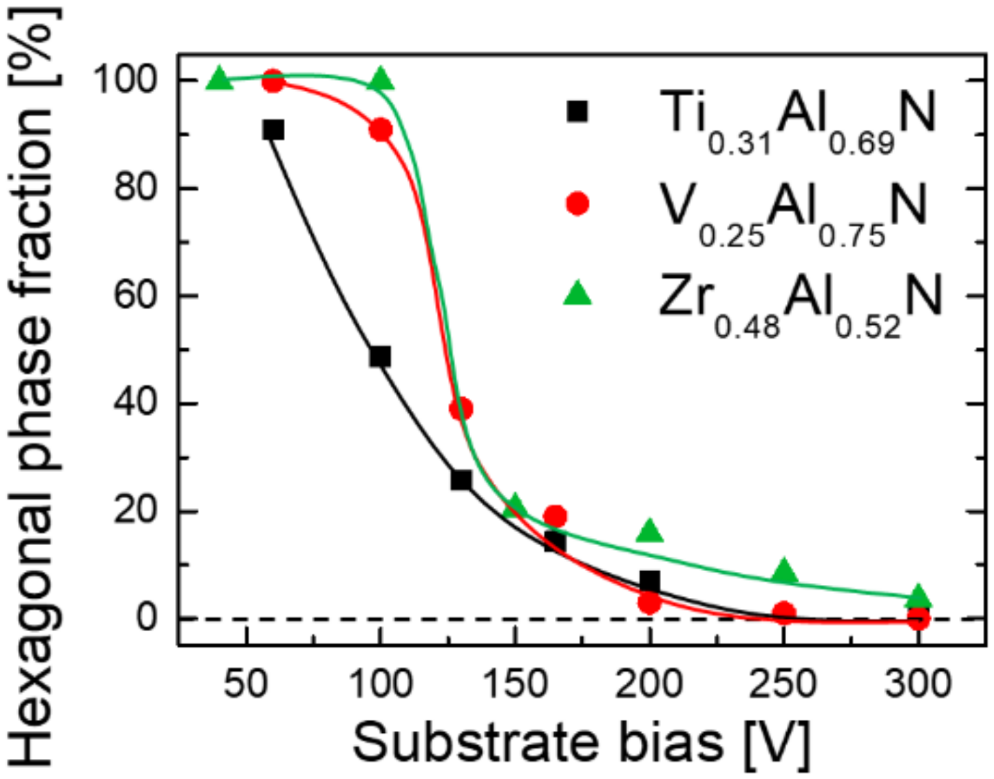
The relative volume fractions χ of w-AlN phase, estimated from wurtzite 10 1 ¯ 0 and NaCl 002 peaks integrated over all ψ angles, are plotted as a function of synchronous bias voltage Vs for Zr0.48Al0.52N, V0.26Al0.74N, and Ti0.31Al0.69N films in Figure 2. Interestingly, in all cases, there is a rapid decrease of the w-AlN phase fraction from χ ≳ 90% with |Vs| ≤ 60 V to χ ≲ 20% with |Vs| ≥ 150 V. Subtle differences are, however, to be noticed. For example, for Zr0.48Al0.52N layers, the largest change in the hexagonal phase content occurs from Vs = –100 V (χ = 100%) to –150 V (χ = 21%), which is similar to the V0.26Al0.74N system, in which case χ drops from 91% to 24% in the same bias voltage range. Ti0.31Al0.69N film behaves somewhat differently in that a large change in χ, from 91% to 49%, is observed at lower Vs values, from –60 to –100 V. Thus, a rapid transition from w-AlN- to NaCl-dominated films, observed for both Zr0.48Al0.52N and V0.26Al0.74N, is not that pronounced in the TiAlN case. Overall, it appears that the ion energy necessary for efficient Al+ subplantation into TM nitrides is in the range of ~150–200 eV.
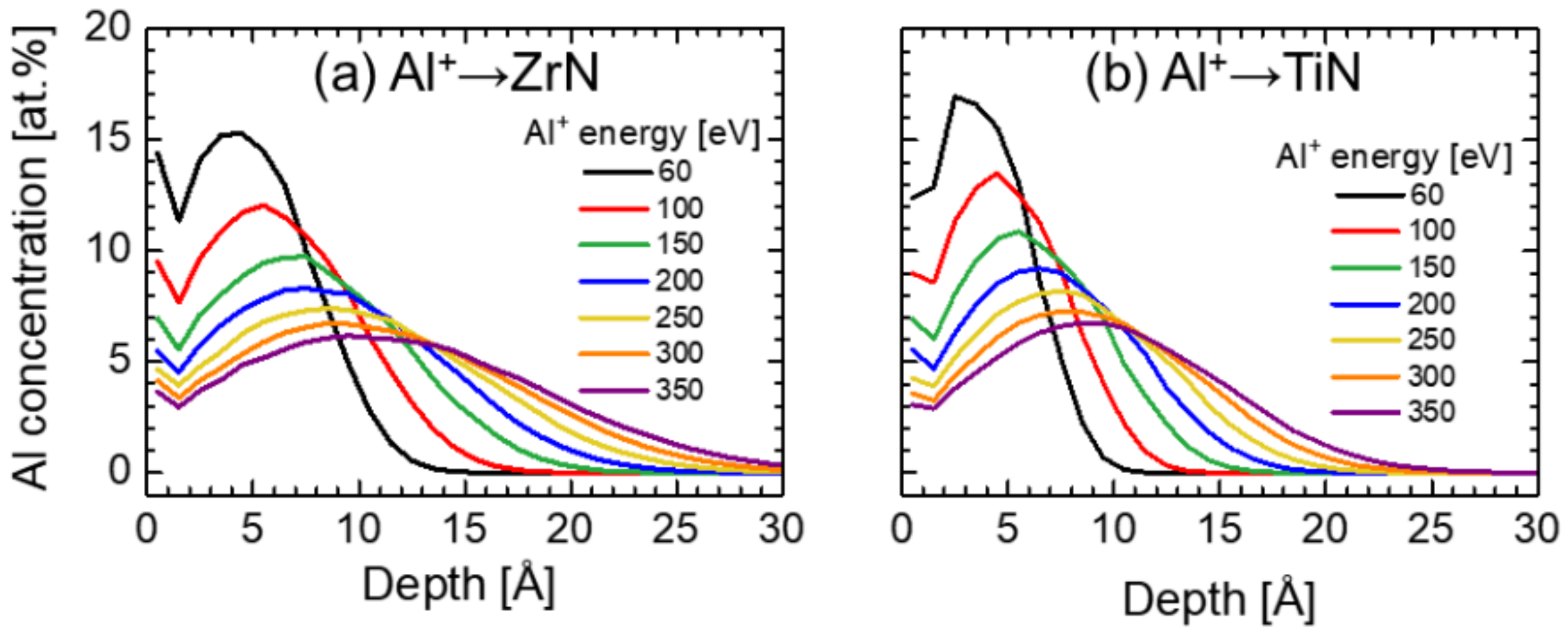
The χ(Vs) plots can be interpreted with the help of Al implantation profiles shown in Figure 3 and obtained from Monte Carlo TRIDYN simulations of Al+ irradiation of (a) ZrN and (b) TiN surface. It can be observed that for both types of nitrides, an increase in the Al+ incident energy EAl+ results in a shift of the most probable implantation depth away from the high-mobility surface zone (defined as 4 Å, which corresponds to about a monolayer nitride thickness) [39]. As a consequence, the Al concentration at depths larger than 10 Å, i.e., below the high mobility zone, increases rapidly with increasing EAl+. For ZrN the Al+ fraction incorporated below the surface, ξAl+ increases from 49% with EAl+ = 60 eV to 84% with EAl+ = 300 eV. In the case of TiN the corresponding numbers are 33% and 79%, respectively.
The authors of the TRIDYN code [40] state that the binary collision approximation (BCA) results in limited validity of the simulation for very low ion energies ≤ 1 eV·amu−1, i.e., ≤ 27 eV for Al+ ions. The here communicated simulation results describing subplantation at 60 to 300 eV are helpful in visualizing the energy dependence of Al+ subplantation. Although the precision of the simulated subplantation profiles, particularly at low energies, may be limited, the energy dependence of the Al implantation profiles is meaningful considering the energy cut off given by the authors and consistent with the here observed phase formation. Clearly, Al is subplanted and a larger fraction of Al is subplanted as the subplantation energy is increased. This effectively suppresses the formation of the thermodynamically stable w-AlN phase as the activation energy for bulk diffusion is larger than for surface diffusion.
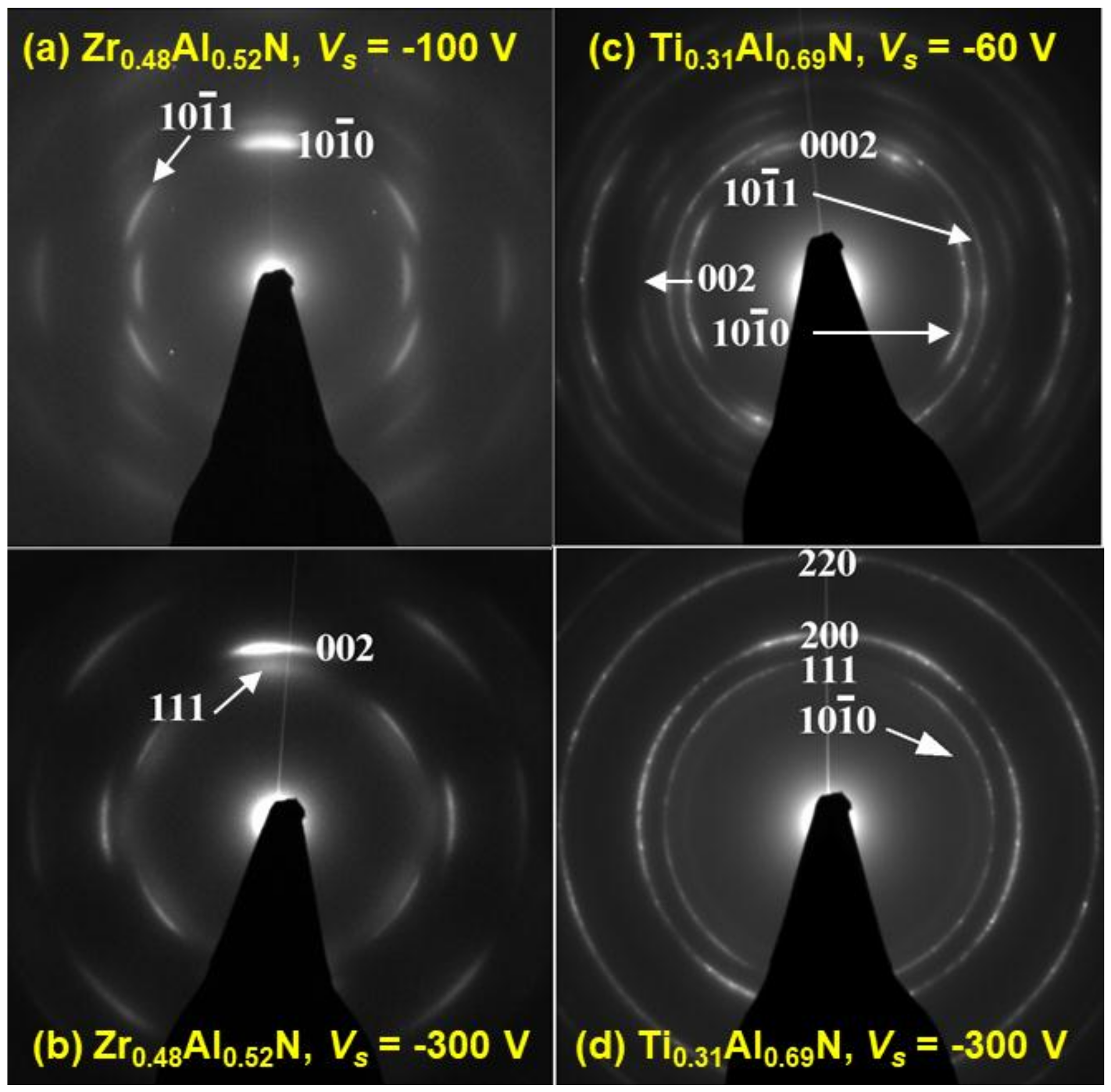
The dramatic change in phase evolution upon variation of the metal-ion-synchronized bias voltage Vs is fully confirmed by SAED patterns obtained from XTEM samples and shown in Figure 4 for Zr0.48Al0.52N (a) Vs = −100 V and (b) Vs = −300 V, and for Ti0.31Al0.69N (c) Vs = −60 V and (d) Vs = −300 V films. The only diffraction rings in SAED obtained from the Zr0.48Al0.52N film grown with Vs = −100 V (Figure 4a) are those from the w-AlN. The film growth direction is 10 1 ¯ 0 , in agreement with XRD results. With increasing the substrate bias amplitude to −300 V, the structure changes to NaCl with the clear 002 preferred orientation as revealed by SAED in Figure 4b. The diffuse pattern on the inner side of the 111 ring may be interpreted as a signature of a 10 1 ¯ 0 w-AlN present in small amounts possibly in a form of (semi-)coherent w-AlN domains of the type reported by for reactively sputtered Zr0.66Al0.34N [41] and Zr0.64Al0.36N [42]. This feature is consistent with the broad shoulders at around 2θ ~ 32° visible in XRD scans recorded at higher tilt angles (cf. Figure 1b).
The SAED recorded from the Vs = −60 V Ti0.31Al0.69N sample (see Figure 4c) consists primarily of w-AlN rings with the 0002 preferred orientation. The 002 signal from the NaCl structure is also detected. Thus, all findings are in agreement with the tilt-angle dependent XRD results discussed above. Ti0.31Al0.69N film grown with Vs = −300 V (Figure 4d) contains primarily NaCl structure diffraction rings with 002 preferred orientation. A weak 10 1 ¯ 0 w-AlN ring is also visible, in agreement with XRD above.
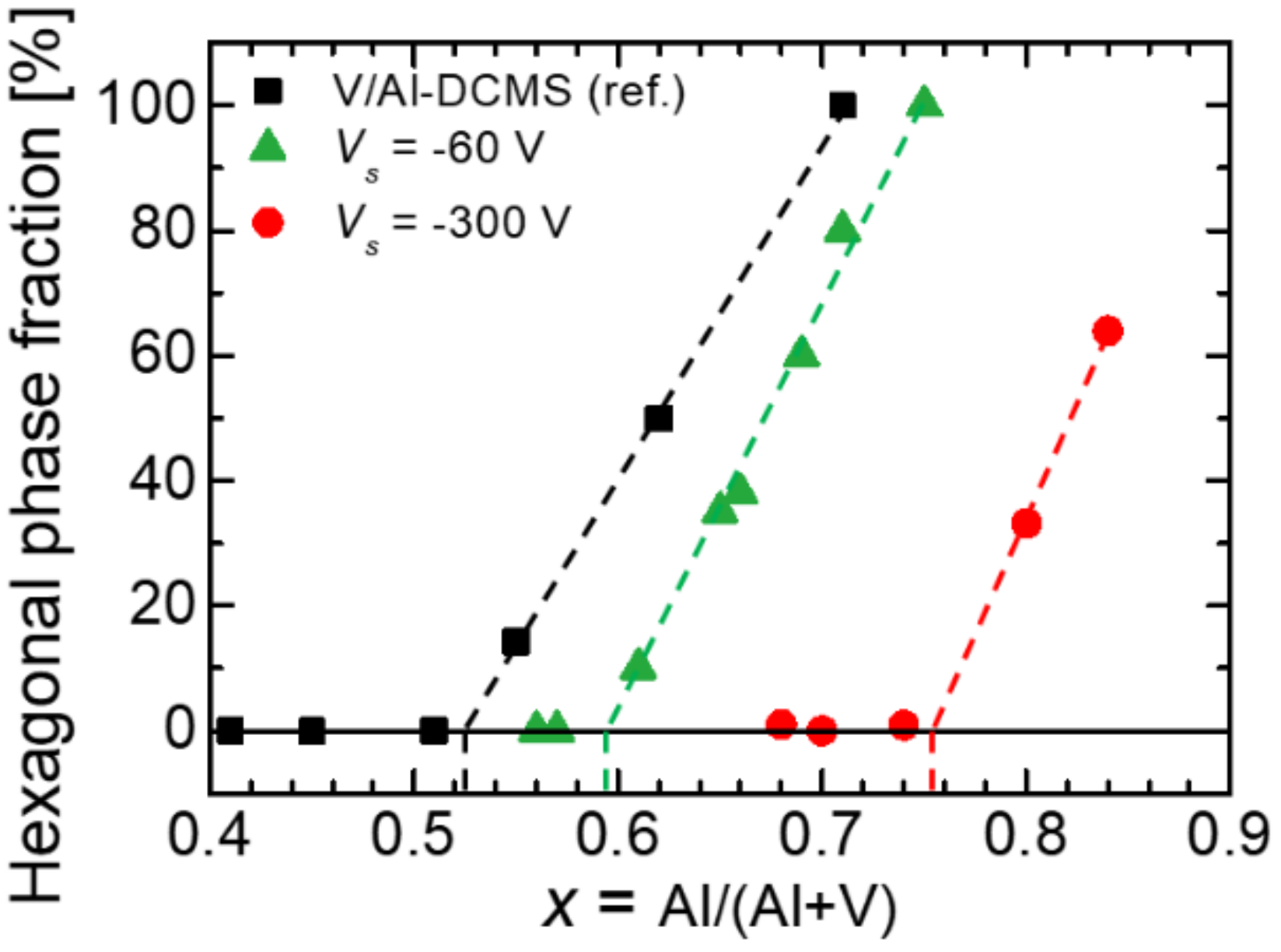
The volume fraction χ of the second-phase w-AlN precipitates, estimated from NaCl phase 002 and wurtzite 10 1 ¯ 0 peak intensities integrated over all sample title angles and normalized to random powder diffraction values, is plotted in Figure 5 as a function of Al concentration x for three series of V1−xAlxN films grown with (a) conventional DCMS and dc bias of −100 V, (data points from [20]) (b) hybrid Al-HiPIMS/V-DCMS co-sputtering with –60 V bias pulses synchronized to the metal-ion rich portions of the HiPIMS pulses, and (c) hybrid Al-HiPIMS/V-DCMS co-sputtering with Vs = −300 V. Linear extrapolations of χ(x) data plots towards the χ = 0 horizontal line are used to estimate the critical Al concentration value xmax, above which w-AlN phase is detected, corresponding to metastable solubility limit of Al in the NaCl crystal lattice. Clearly, solubility is lowest for the V1−xAlxN films grown with conventional DCMS technique and with a DC substrate bias of –100 V, xmax = 0.52. A higher value of xmax = 0.59, is achieved for layers grown by Al-HiPIMS/V-DCMS and with synchronous Vs = –60 V, which may indicate that some Al+ subplantation takes place already at this low Vs amplitude. Higher bias amplitude of –300 V, corresponding to ~300 eV Al+ irradiation, results in xmax = 0.75, which is 44% higher than that obtained with DCMS sputtering.
The potential of the metal-ion-synchronized HiPIMS for the formation of supersaturated thin film alloys, demonstrated here for ZrAlN, VAlN, and TiAlN systems, is due to the intentional separation of film-forming species in time and energy domains in order to avoid that Al is present in the high-mobility surface region, thereby enabling the formation of the thermodynamically-favored wurtzite phase. The time separation results from the hybrid co-sputtering setup, in which the growth surface is irradiated predominantly by Al+ metal-ions during the ~100 μs-long period starting 30 μs after the ignition of the HiPIMS pulse (i.e., 5% of the deposition time), while between HiPIMS pulses (for 95% of the deposition time) the surface is exposed to metal neutrals (here: Zr, V or Ti) together with low-energy (~10 eV) gas ions (Ar+, N2+, and N+). The energy separation between Al and other TM deposited from the DCMS source is obtained by advanced biasing scheme, in which the synchronization of the bias pulse to the Al+-rich portion of the ion flux originating from the HiPIMS-driven target enables precise control over the incident energy and, hence, over the subplantation depth of the ionized Al flux (see Figure 3), which can be easily extended to exceed the thickness of the surface high-mobility zone ξ. To further enhance the separation of subplanted Al from TM neutrals residing at the very surface, ξ is minimized by keeping the substrate at the floating potential between Al+ HiPIMS pulses, i.e., when gas-ion flux dominates over that of Al+ (which is also the time when the majority of TM-DCMS flux arrives), meaning that the incident energies of gas ions are below the lattice displacement threshold. Thus, the film structure evolution is determined, to a great extent, by metal-ion irradiation during metal-ion-rich HiPIMS phase. The latter has a clear advantage over gas-ion-assisted growth in that metal-ions are incorporated into the structure, while, in contrast, gas ions are trapped in the interstitial sites [43] leading to high compressive stress [44,45] and, as a consequence, to cohesive and/or adhesive film failure [46,47].
In the growth scenario described above, the composition at the high-mobility surface layer is set by the TM neutrals from the DCMS source deposited predominantly between HiPIMS pulses and the non-ionized portion of the Al-HiPIMS flux, both arriving with an energy of a few eV. TM-DCMS source ensures that the low-energy gas ion irradiation continuously enables surface diffusion. Formation of low-Al content metastable, NaCl-structure (TM)AlN prevails at the surface as long as TM neutral flux dominates over that of Al. Since a significant portion of the Al flux during Al-HiPIMS is ionized, upon application of sufficiently high Vs, the Al concentration at the surface is lowered due to subplantation, preventing the formation of the w-AlN (which is otherwise observed) in the high-mobility surface zone. Al+ arriving with EAl+ ~ 300 eV is effectively subplanted at depths exceeding 10 Å (see Figure 3), i.e., directly into the cubic TM-rich (TM)1−xAlxN matrix triggering local mobility on cation lattice and subsequent quenching, thus enabling the formation of the single-phase rock salt structure metastable solid solution. As the activation energy for bulk diffusion is larger than for surface diffusion, the mobility on the cation lattice is limited to few neighboring sites. The subplantation-induced mobility on the cation sublattice is insufficient to cause nucleation and growth of w-AlN with a larger molar volume than the resulting Al supersaturated cubic (TM)AlN phase. xmax is limited by the ionization degree of the Al-HiPIMS flux: The concentration of non-ionized Al in the high-mobility surface zone increases and, once it exceeds that of TM, w-AlN begins to form.
There are different reasons responsible for the presence of the small w-AlN content in Zr0.48Al0.52N and Ti0.31Al0.69N films grown with synchronous ~300 eV Al+ irradiation (Vs = −300 V). First, the bias pulse length (100 μs) and the phase shift (30 μs) are determined based upon the ion mass spectrometry analyses performed for the Al-HiPIMS/V-DCMS configuration [28], and both can be sensitive to the choice of the elemental target operating in DCMS mode. Secondly, there is always a certain degree of time overlap between metal-ion and gas-ion fluxes incident at the growing film surface, which implies a risk that either (a) not all of the Al+ is accelerated by the applied Vs and, thus, resides at the very surface, or (b) gas-ions are affected by the high-amplitude bias pulse leading to point defect creation. Both of the above facilitate formation of the hexagonal phase. Thirdly, not all of the sputtered Al is ionized, again residing at the very surface high-mobility zone, where w-AlN formation is likely to take place. Another reason for the latter to occur is the potential presence of Ti2+ in the ion flux incident at the film due to cross-contamination between Al and Ti sources originating from the fact that Al target is off for 98% of the deposition time, while Ti operates continuously. Ti redeposited on the Al target can likely form Ti2+ while passing through a dense plasma during HiPIMS pulse due to the relatively low Ti second ionization potential, which is lower than the first ionization potential of Ar [48]. The evidence for the detrimental role of Ti2+ ion bombardment for properties of TiAlN films related to the w-AlN formation at relatively low Al content comes from experiments conducted in the Ti-HiPIMS/Al-DCMS configuration [24].
Recently, direct experimental evidence has been presented for the determining role of the precise bias pulse synchronization (phase shift and pulse duration) with the Al+-rich portion of the HiPIMS pulses for the phase formation in VAlN [28]. Making the bias pulses intentionally either too short or too long by as little as 30 μs (with respect to parameters used to grown single-phase NaCl-structure V0.26Al0.74N), while keeping all other process parameters unchanged, resulted in layers that contained clear contributions of the w-AlN phase. This is caused by the fact that either (too short Vs pulses) a significant fraction of the Al+ flux is not subplanted, thus, lands at the very surface, where high mobility removes kinetic constraints, resulting in precipitation of w-AlN, or (too long Vs pulses) the Ar+ and N2+ ions, dominating the flux at all other times, gain high energy in the electric field of the substrate and induce point defects that serve as nucleation sites for the formation of w-AlN precipitates at relatively low AlN concentrations [49,50,51].
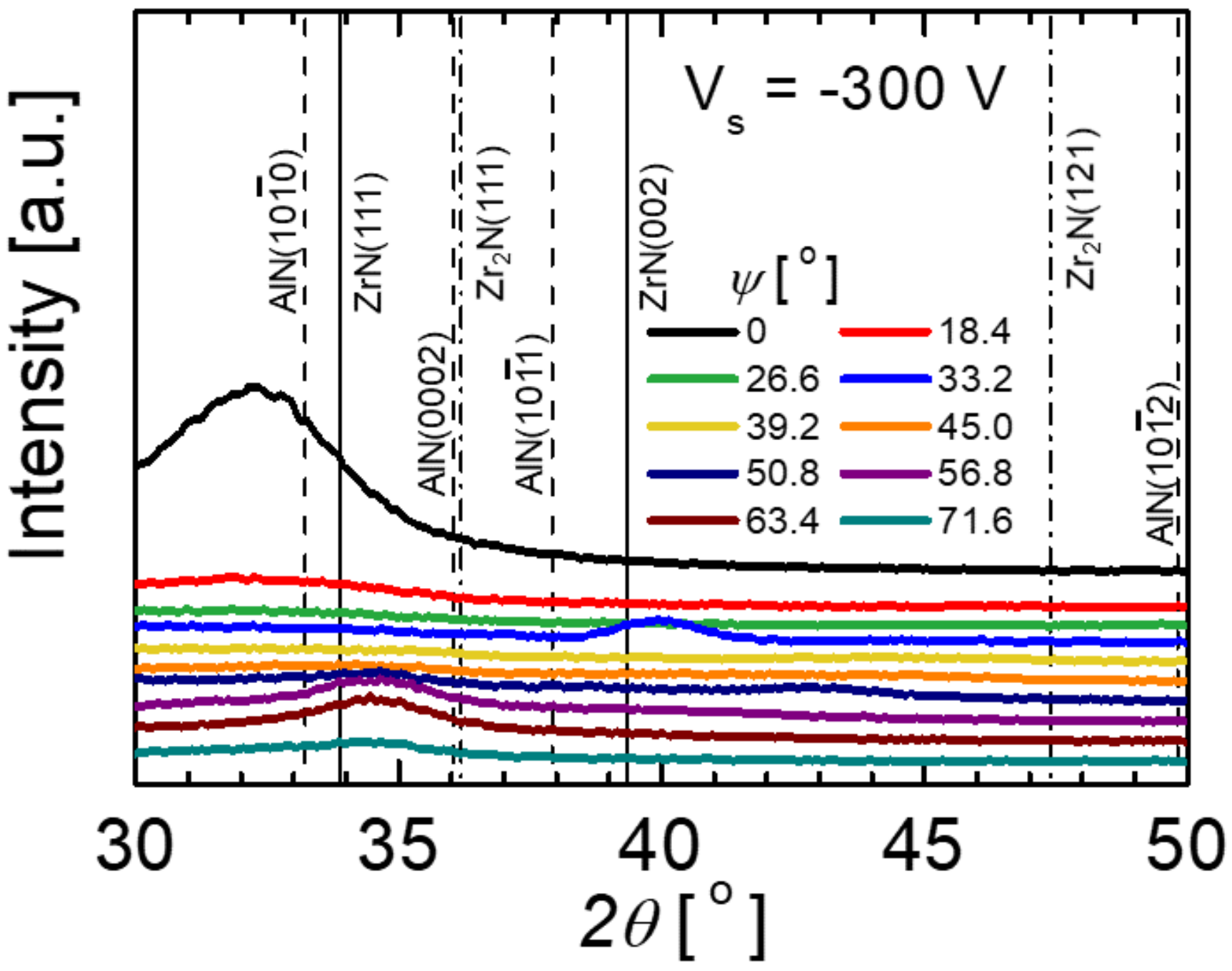
Further proof for a controlling role of Al+ ion irradiation utilized here for manipulation of the crystalline phase content by means of synchronized substrate bias pulses, is presented in Figure 6, which shows a set of θ–2θ XRD scans acquired as a function of the sample tilt angle ψ from Zr0.48Al0.52N films grown with Vs = −300 V applied in phase with the incoming Al+ flux. However, the HiPIMS current density is intentionally reduced (by increasing pulsing frequency) to the levels that are more characteristic for conventional DCMS, from 1 A·cm−2 employed to grow supersaturated alloys (Figure 1b and Figure 4b) to 0.05 A·cm−2. Under the latter conditions the ionization of the sputtered Al flux is negligible [52,53], thus, the growth proceeds predominantly from neutrals. As a consequence, the NaCl phase content is drastically reduced and Zr0.48Al0.52N films possess predominantly w-AlN phase, as revealed by XRD patters in Figure 6. In addition, the concentration of Ar is extremely high at 9 at.% vs. 1 at.% in the Zr0.48Al0.52N layer grown with JT,peak = 1 A·cm−2, which can be explained by the fact that during the application of the high-amplitude Vs the ion flux incident on the growing film surface is dominated by Ar+ that is then efficiently implanted at the interstitial sites.

4. Conclusions

In summary, we present experimental evidence that a coating synthesis strategy based on separating the film-forming metallic species in time and energy domains allows for control over the metastable Al solid solubility, hence, crystalline phase content, in Zr0.48Al0.52N, V0.26Al0.74N, and Ti0.31Al0.69N. For each materials system, with the Al content intentionally chosen to be higher than the theoretically predicted solubility limit, varying the amplitude of the synchronous bias pulse Vs, thus, the incident energy of the Al+ ions, without affecting gas-ion irradiation, allows the manipulation of the volume fraction of the w-AlN phase from more than 95% with low Vs values (−60 V) to less than 5% for Vs of –300 V. The critical Al+ energy necessary for efficient subplantation of Al is estimated to be in the range ~150–200 eV, thus maintaining cubic-phase nitride growth conditions on the film surface. Independent experiments performed for the Zr0.48Al0.52N system in the same setup, with varied ionization degree of the Al flux, prove that the presence of significant Al+ flux incident at the growing film surface is indeed necessary for the control of the crystalline phase formation. Based on these results, we infer that the subplantation mechanism offers a powerful tool to realize the formation of metastable transition metal aluminum compounds outside of the predicted metastable solubility range.

Author Contributions

Conceptualization: G.G., J.M.S. and L.H.; Formal Analysis: S.M., J.M.S. and L.H.; Investigation: S.M., G.G., M.H. and J.L.; Resources: J.M.S. and L.H.; Data Curation: G.G., M.H. and J.L.; Writing—Original Draft Preparation: G.G.; Writing—Review & Editing: S.M., M.H., J.L., J.M.S. and L.H.; Project Administration: J.M.S. and L.H.; Funding Acquisition: J.M.S. and L.H.; All authors discussed results.

Funding

This research was funded by the German Research Foundation (DFG) within SFB-TR 87, the VINN Excellence Center Functional Nanoscale Materials (FunMat-2) (No. 2016-05156), the Knut and Alice Wallenberg Foundation Scholar (No. KAW2016.0358), the Åforsk Foundation (No. 16-359), the Swedish Research Council VR (No. 2018-03957), and Carl Tryggers Stiftelse contract (No. CTS 17:166), the operation of the accelerator laboratory in Uppsala by VR-RFI (contract 821-2012-5144) and the Swedish Foundation for Strategic Research (SSF, contract RIF14-0053).

Acknowledgments

The authors most gratefully acknowledge the support of Daniel Primetzhofer from Uppsala University with the ToF-ERDA experiments.

Conflicts of Interest

The authors declare no conflict of interest.

References and Notes

  1. Knotek, O.; Münz, W.D.; Leyendecker, T. Industrial deposition of binary, ternary, and quaternary nitrides of titanium, zirconium, and aluminum. J. Vac. Sci. Technol. A 1987, 5, 2173–2179. [Google Scholar] [CrossRef]
  2. Mayrhofer, P.H.; Mitterer, C.; Hultman, L.; Clemens, H. Microstructural design of hard coatings. Prog. Mater. Sci. 2006, 51, 1032–1114. [Google Scholar] [CrossRef]
  3. Knotek, O.; Löffler, F.; Krämer, G. Multicomponent and multilayer physically vapour deposited coatings for cutting tools. Surf. Coat. Technol. 1992, 54–55, 241–248. [Google Scholar] [CrossRef]
  4. Munz, W.-D. Titanium aluminum nitride films: A new alternative to TiN coatings. J. Vac. Sci. Technol. A 1986, 4, 2717–2725. [Google Scholar] [CrossRef]
  5. Hörling, A.; Hultman, L.; Odén, M.; Sjölén, J.; Karlsson, L. Mechanical properties and machining performance of Ti1−xAlxN-coated cutting tools. Surf. Coat. Technol. 2005, 191, 384–392. [Google Scholar] [CrossRef]
  6. Kimura, A.; Hasegawa, H.; Yamada, K.; Suzuki, T. Effects of Al content on hardness, lattice parameter and microstructure of Ti1−xAlxN films. Surf. Coat. Technol. 1999, 120–121, 438–441. [Google Scholar] [CrossRef]
  7. Hörling, A.; Hultman, L.; Odén, M.; Sjölén, J.; Karlsson, L. Thermal stability of arc evaporated high aluminum-content Ti1−xAlxN thin films. J. Vac. Sci. Technol. A 2002, 20, 1815–1823. [Google Scholar] [CrossRef]
  8. Mayrhofer, P.H.; Hörling, A.; Karlsson, L.; Mitterer, C.; Hultman, L. Self-organized nanostructures in the Ti–Al–N system. Appl. Phys. Lett. 2003, 83, 2049–2051. [Google Scholar] [CrossRef]
  9. Knutsson, A.; Johansson, M.P.; Persson, P.O.Å.; Odén, M. Thermal decomposition products in arc evaporated TiAlN/TiN multilayers. Appl. Phys. Lett. 2008, 93, 143110. [Google Scholar] [CrossRef]
  10. Holec, D.; Rachbauer, R.; Chen, L.; Wang, L.; Luef, D.; Mayrhofer, P.H. Phase stability and alloy-related trends in Ti–Al–N, Zr–Al–N and Hf–Al–N systems from first principles. Surf. Coat. Technol. 2011, 206, 1698–1704. [Google Scholar] [CrossRef]
  11. Sheng, S.H.; Zhang, R.F.; Veprek, S. Phase stabilities and thermal decomposition in the Zr1−xAlxN system studied by ab initio calculation and thermodynamic modeling. Acta Mater. 2008, 56, 968–976. [Google Scholar] [CrossRef]
  12. Alling, B.; Ruban, A.V.; Karimi, A.; Peil, O.E.; Simak, S.I.; Hultman, L.; Abrikosov, I.A. Mixing and decomposition thermodynamics of c−Ti1−xAlxN from first-principles calculations. Phys. Rev. B 2007, 75, 045123. [Google Scholar] [CrossRef]
  13. Hans, M.; Music, D.; Chen, Y.-T.; Patterer, L.; Eriksson, A.O.; Kurapov, D.; Ramm, J.; Arndt, M.; Rudigier, H.; Schneider, J.M. Crystallite size-dependent metastable phase formation of TiAlN coatings. Sci. Rep. 2017, 7, 16096. [Google Scholar] [CrossRef] [PubMed] [Green Version]
  14. Wahlström, U.; Hultman, L.; Sundgren, J.-E.; Adibi, F.; Petrov, I.; Greene, J.E. Crystal growth and microstructure of polycrystalline Ti1−xAlxN alloy films deposited by ultra-high-vacuum dual-target magnetron sputtering. Thin Solid Films 1993, 235, 62–70. [Google Scholar] [CrossRef]
  15. Adibi, F.; Petrov, I.; Greene, J.E.; Wahlstrom, U.; Sundgren, J.-E. Design and characterization of a compact two-target ultrahigh vacuum magnetron sputter deposition system: Application to the growth of epitaxial Ti1−xAlxN alloys and TiN/Ti1−xAlxN superlattices. J. Vac. Sci. Technol. A 1993, 11, 136–142. [Google Scholar] [CrossRef]
  16. Makino, Y.; Moria, M.; Miyakea, S.; Saitob, K.; Asami, K. Characterization of Zr–Al–N films synthesized by a magnetron sputtering method. Surf. Coat. Technol. 2005, 193, 219–222. [Google Scholar] [CrossRef]
  17. Araiza, J.J.; Sanchez, O.; Albella, J.M. Influence of the aluminum incorporation on the structure of sputtered ZrNx films deposited at low temperatures. Vacuum 2009, 83, 1236–1239. [Google Scholar] [CrossRef]
  18. Lamni, R.; Sanjinés, R.; Parlinska-Wojtan, M.; Karimi, A.; Lévy, F. Microstructure and nanohardness properties of Zr–Al–N and Zr–Cr–N thin films. J. Vac. Sci. Technol. A 2005, 23, 593–598. [Google Scholar] [CrossRef]
  19. Rovere, F.; Music, D.; Ershov, S.; Baben, M.t.; Fuss, H.-G.; Mayrhofer, P.H.; Schneider, J.M. Experimental and computational study on the phase stability of Al-containing cubic transition metal nitrides. J. Phys. D Appl. Phys. 2010, 43, 035302. [Google Scholar] [CrossRef]
  20. Greczynski, G.; Mráz, S.; Ruess, H.; Hans, M.; Lu, J.; Hultman, L.; Schneider, J.M. Extended metastable Al solubility in cubic VAlN by metal-ion bombardment during pulsed magnetron sputtering: Film stress vs subplantation. J. Appl. Phys. 2017, 122, 025304. [Google Scholar] [CrossRef]
  21. Zhu, P.; Ge, F.; Li, S.; Xue, Q.; Huang, F. Microstructure, chemical states, and mechanical properties of magnetron co-sputtered V1−xAlxN coatings. Surf. Coat. Technol. 2013, 232, 311–318. [Google Scholar] [CrossRef]
  22. Greczynski, G.; Mráz, S.; Hans, M.; Primetzhofer, D.; Lu, J.; Hultman, L.; Schneider, J.M. Unprecedented Al supersaturation in single-phase rock salt structure VAlN films by Al+ subplantation. J. Appl. Phys. 2017, 121, 171907. [Google Scholar] [CrossRef]
  23. Kouznetsov, V.; Macak, K.; Schneider, J.M.; Helmersson, U.; Petrov, I. A novel pulsed magnetron sputter technique utilizing very high target power densities. Surf. Coat. Technol. 1999, 122, 290–293. [Google Scholar] [CrossRef]
  24. Greczynski, G.; Lu, J.; Johansson, M.; Jensen, J.; Petrov, I.; Greene, J.E.; Hultman, L. Role of Tin+ and Aln+ ion irradiation (n = 1, 2) during Ti1-xAlxN alloy film growth in a hybrid HIPIMS/magnetron mode. Surf. Coat. Technol. 2012, 206, 4202–4211. [Google Scholar] [CrossRef]
  25. Greczynski, G.; Patscheider, J.; Lu, J.; Alling, B.; Ektarawong, A.; Jensen, J.; Petrov, I.; Greene, J.E.; Hultman, L. Control of Ti1−xSixN nanostructure via tunable metal-ion momentum transfer during HIPIMS/DCMSco-deposition. Surf. Coat. Technol. 2015, 280, 174–184. [Google Scholar] [CrossRef]
  26. Greczynski, G.; Lu, J.; Petrov, I.; Greene, J.E.; Bolz, S.; Kölker, W.; Schiffers, C.; Lemmer, O.; Hultman, L. Novel strategy for low-temperature, high-rate growth of dense, hard, and stress-free refractory ceramic thin films. J. Vac. Sci. Technol. A 2014, 32, 041515. [Google Scholar] [CrossRef] [Green Version]
  27. Greczynski, G.; Petrov, I.; Greene, J.E.; Hultman, L. Strategy for tuning the average charge state of metal ions incident at the growing film during HIPIMS deposition. Vacuum 2015, 116, 36–41. [Google Scholar] [CrossRef] [Green Version]
  28. Greczynski, G.; Mráz, S.; Hultman, L.; Schneider, J.M. Selectable phase formation in VAlN thin films by controlling Al+ subplantation depth. Sci. Rep. 2017, 7, 17544. [Google Scholar] [CrossRef]
  29. Available online: https://www.cemecon.de/en/coating-plants/cc-800-hipims (accessed on 27 December 2018).
  30. Greczynski, G.; Mráz, S.; Hultman, L.; Schneider, J.M. Venting temperature determines surface chemistry of magnetron sputtered TiN films. Appl. Phys. Lett. 2016, 108, 041603. [Google Scholar] [CrossRef] [Green Version]
  31. Ström, P.; Petersson, P.; Rubel, M.; Possnert, G. A combined segmented anode gas ionization chamber and time-of-flight detector for heavy ion elastic recoil detection analysis. Rev. Sci. Instrum. 2016, 87, 103303. [Google Scholar] [CrossRef]
  32. Baben, M.; Hans, M.; Primetzhofer, D.; Evertz, S.; Ruess, H.; Schneider, J.M. Unprecedented thermal stability of inherently metastable titanium aluminum nitride by point defect engineering. Mater. Res. Lett. 2017, 5, 158–169. [Google Scholar] [CrossRef]
  33. The JCPDS Database, Data Set Number: 25-1133; International Center for Diffraction Data: Newtown Square, PA, USA, 1998.
  34. The JCPDS Database, Data Set Number: 35-0753; International Center for Diffraction Data: Newtown Square, PA, USA, 1998.
  35. Kohn, J.A.; Cotter, P.G.; Potter, R.A. Synthesis of aluminum nitride monocrystals. Am. Miner. 1956, 41, 355–359. [Google Scholar]
  36. Birkholz, M.; Genzel, C. Residual stress analysis. In Thin Film Analysis by X-Ray Scattering; Birkholz, M., Ed.; Wiley-VCH: Weinheim, Germany, 2006; pp. 239–295. [Google Scholar]
  37. The JCPDS Database, Data Set Number: 35-0768; International Center for Diffraction Data: Newtown Square, PA, USA, 1998.
  38. The JCPDS Database, Data Set Number: 38-1420; International Center for Diffraction Data: Newtown Square, PA, USA, 1998.
  39. The first ~1 Å from the surface was not considered in the fraction calculation of the implanted Al+.
  40. Möller, W.; Eckstein, W.; Biersack, J.P. TRIDYN—Binary collision simulation of atoms collisions and dynamic composition changes in solids. Comput. Phys. Commun. 1988, 51, 355–368. [Google Scholar] [CrossRef]
  41. Mayrhofer, P.H.; Sonnleitner, D.; Bartosik, M.; Holec, D. Structural and mechanical evolution of reactively and non-reactively sputtered Zr–Al–N thin films during annealing. Surf. Coat. Technol. 2014, 244, 52–56. [Google Scholar] [CrossRef] [PubMed]
  42. Ghafoor, N.; Johnson, L.; Klenov, D.O.; Demeulemeester, J.; Desjardins, P.; Petrov, I.; Hultman, L.; Odén, M. Nanolabyrinthine ZrAlN thin films by self-organization of interwoven single-crystal cubic and hexagonal phases. Appl. Phys. Lett. Mater. 2013, 1, 022105. [Google Scholar] [CrossRef] [Green Version]
  43. Hultman, L.; Sundgren, J.-E.; Greene, J.E. Formation of polyhedral N2 bubbles during reactive sputter deposition of epitaxial TiN (100) films. J. Appl. Phys. 1989, 66, 536–544. [Google Scholar] [CrossRef]
  44. Davis, C.A. A simple model for the formation of compressive stress in thin films by ion bombardment. Thin Solid Films 1993, 226, 30–34. [Google Scholar] [CrossRef]
  45. Ulrich, S.; Theel, T.; Schwan, J.; Ehrhardt, H. Magnetron-sputtered superhard materials. Surf. Coat. Technol. 1997, 97, 45–59. [Google Scholar] [CrossRef]
  46. Teixeira, V. Mechanical integrity in PVD coatings due to the presence of residual stresses. Thin Solid Films 2001, 392, 276–281. [Google Scholar] [CrossRef]
  47. Oettel, H.; Wiedemann, R. Residual stresses in PVD hard coatings. Surf. Coat. Technol. 1995, 76, 265–273. [Google Scholar] [CrossRef]
  48. Lide, D.R. CRC Handbook of Chemistry and Physics, 84th ed.; CRC Press: Boca Raton, FL, USA, 2003. [Google Scholar]
  49. Petrov, I.; Hultman, L.; Helmersson, U.; Sundgren, J.-E.; Greene, J.E. Microstructure modification of TiN by ion bombardment during reactive sputter deposition. Thin Solid Films 1989, 169, 299–314. [Google Scholar] [CrossRef]
  50. Petrov, I.; Barna, P.B.; Hultman, L.; Greene, J.E. Microstructural evolution during film growth. J. Vac. Sci. Technol. A 2003, 21, S117–S128. [Google Scholar] [CrossRef]
  51. Music, D.; Banko, L.; Ruess, H.; Engels, M.; Hecimovic, A.; Grochla, D.; Rogalla, D.; Brögelmann, T.; Ludwig, A.; von Keudell, A.; Bobzin, K. Correlative plasma-surface model for metastable Cr–Al–N: Frenkel pair formation and influence of the stress state on the elastic properties. J. Appl. Phys. 2017, 121, 215108. [Google Scholar] [CrossRef]
  52. Greczynski, G.; Hultman, L. Peak amplitude of target current determines deposition rate loss during high power pulsed magnetron sputtering. Vacuum 2016, 124, 1–4. [Google Scholar] [CrossRef] [Green Version]
  53. Greczynski, G.; Zhirkov, I.; Petrov, I.; Greene, J.E.; Rosen, J. Gas rarefaction effects during high power pulsed magnetron sputtering of groups IVb and VIb transition metals in Ar. J. Vac. Sci. Technol. A 2017, 35, 060601. [Google Scholar] [CrossRef] [Green Version]
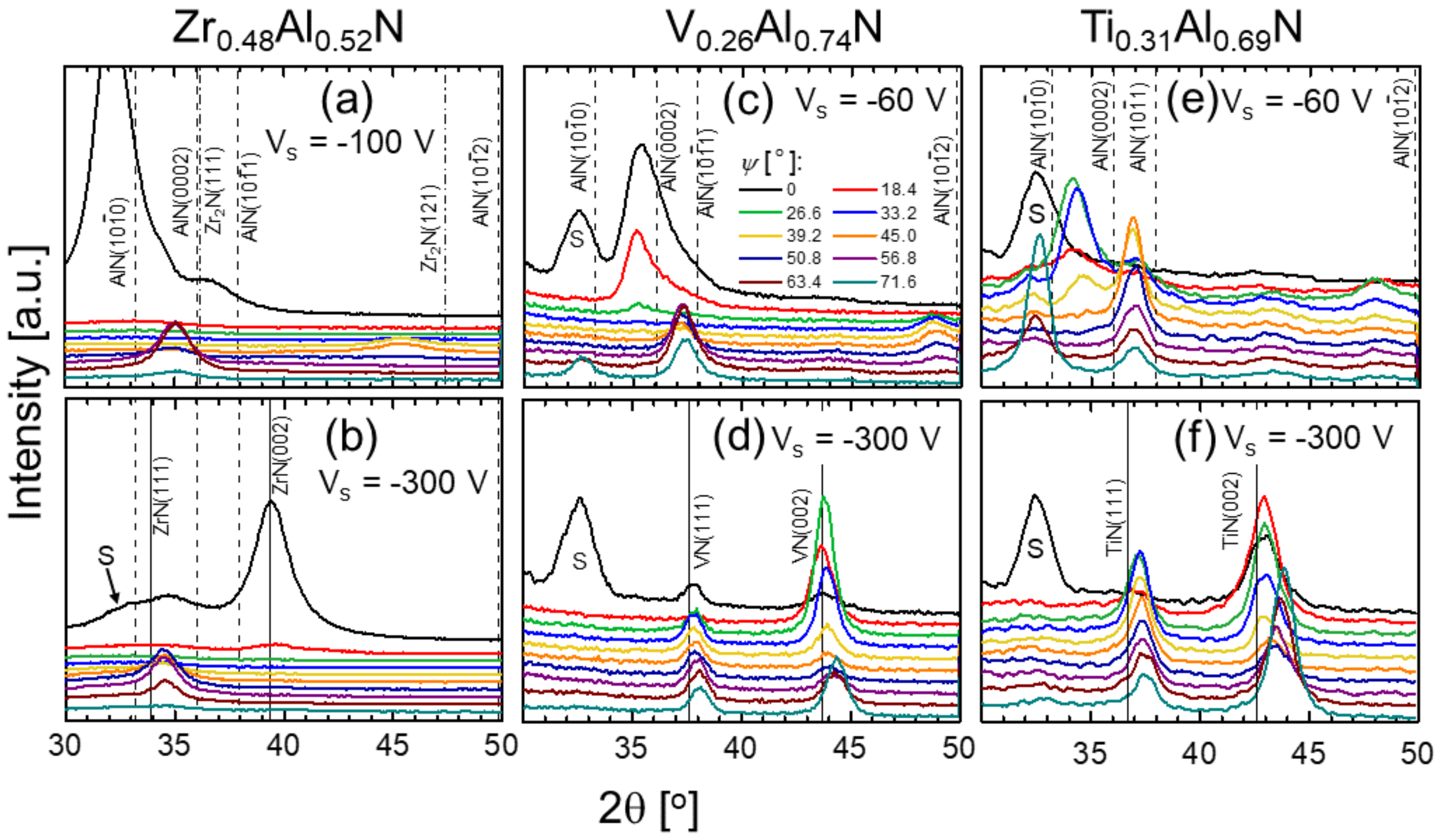
Figure 1. X-ray diffraction (XRD) θ–2θ scans recorded as a function of the tilt angle ψ for: (a) Zr0.48Al0.52N (Vs = −100 V); (b) Zr0.48Al0.52N (Vs = –300 V); (c) V0.26Al0.74N (Vs = –60 V); (d) V0.26Al0.74N (Vs = –300 V); (e) Ti0.31Al0.69N (Vs = –60 V); and (f) Ti0.31Al0.69N (Vs = –300 V) films. “S” denotes the forbidden 002 reflection from the Si substrate, which appears due to multiple scattering.
Coatings 09 00017 g001
Figure 2. Relative w-AlN content extracted from the areas of wurtzite 10 1 ¯ 0 and rock salt structure 002 diffraction peaks integrated over all ψ angles and normalized to random powder XRD patterns plotted as a function of the synchronous bias voltage for Zr0.48Al0.52N, V0.26Al0.74N, and Ti0.31Al0.69N films.
Coatings 09 00017 g002
Figure 3. Al implantation profiles obtained from TRIDYN simulations as a function of Al+ energy for metal-ions incident on (a) ZrN and (b) TiN.
Coatings 09 00017 g003
Figure 4. Selected area electron diffraction patterns for: Zr0.48Al0.52N (a) Vs = −100 V and (b) Vs = −300 V; and for Ti0.31Al0.69N (c) Vs = −60 V and (d) Vs = −300 V films.
Coatings 09 00017 g004
Figure 5. Relative w-AlN content extracted from the areas of wurtzite 10 1 ¯ 0 and rock salt structure 002 diffraction peaks integrated over all ψ angles and normalized to random powder XRD patterns plotted as a function of Al concentration x for V1−xAlxN films grown with (a) conventional direct current magnetron sputtering (DCMS) (Al/V-DCMS), (b) hybrid Al-HiPIMS/V-DCMS with synchronous substrate bias of −60 V, and (c) hybrid Al-HiPIMS/V-DCMS with synchronous substrate bias of −300 V. The critical Al solubilities xmax are obtained by extrapolation.
Coatings 09 00017 g005
Figure 6. The set of XRD θ–2θ scans recorded as a function of the tilt angle ψ from Zr0.48Al0.52N films grown with the synchronized substrate bias with the amplitude Vs −300 V and the HiPIMS current density intentionally reduced to 0.05 A·cm−2, which is characteristic of conventional DCMS.
Coatings 09 00017 g006