Abstract
High-Si-content transition metal nitride coatings, which exhibited an X-ray amorphous phase, were proposed as protective coatings on glass molding dies. In a previous study, the Zr–Si–N coatings with Si contents of 24–30 at.% exhibited the hardness of Si3N4, which was higher than those of the middle-Si-content (19 at.%) coatings. In this study, the bonding characteristics of the constituent elements of Zr–Si–N coatings were evaluated through X-ray photoelectron spectroscopy. Results indicated that the Zr 3d5/2 levels were 179.14–180.22 and 180.75–181.61 eV for the Zr–N bonds in ZrN and Zr3N4 compounds, respectively. Moreover, the percentage of Zr–N bond in the Zr3N4 compound increased with increasing Si content in the Zr–Si–N coatings. The Zr–N bond of Zr3N4 dominated when the Si content was >24 at.%. Therefore, high Si content can stabilize the Zr–N compound in the M3N4 bonding structure. Furthermore, the thermal stability and chemical inertness of Zr–Si–N coatings were evaluated by conducting thermal cycle annealing at 270 °C and 600 °C in a 15-ppm O2–N2 atmosphere. The results indicated that a Zr22Si29N49/Ti/WC assembly was suitable as a protective coating against SiO2–B2O3–BaO-based glass for 450 thermal cycles.
  1. Introduction
Glass molding [,,] has become a vital technique to fabricate aspherical lenses utilized as optical elements for image capture systems in cameras and mobile phones. Protective coatings on glass molding dies are crucial because molding processes are conducted at molding temperatures that are within the range of glass materials’ softening points to deform the glass into the final lens shape []. Moreover, to be suitable for mass production, molding dies must endure a thermal cycle at temperatures ranging from room temperature to molding temperatures under high pressing loads. Therefore, the requirements of protective coatings are high hardness, smooth surface morphology, high thermal stability, adequate adhesion, long cyclability, and chemical inertness. Following the successful utilization of noble metal alloys [,,,,,,,] and carbon films [,], transition metal nitride films [,,,,,,,,,], which offer cost reduction and process control benefits, have become candidates for protective coatings. The oxidation resistance levels of some transition metal nitrides have been improved by the introduction of Si; in particular, improvements to Ti–Si–N [,,] and Zr–Si–N [,,] coatings have been reported. The improved oxidation resistance was attributed to the absence of grain boundaries in the nitride coatings []. However, the advances in the oxidation resistance were accompanied by a decline in the mechanical properties due to the increase of amorphous volume. In our previous study [], the nanoindentation hardness values of Zr–Si–N coatings with Si levels of 1–19 at.% increased initially with increasing Si content, peaked, and then dropped to lower levels for higher Si levels, which followed the typical mechanical characteristics of M–Si–N coatings (M: transition metal). However, the coatings with an Si level of 24–30 at.% exhibited the hardness level of Si3N4, which was higher than that of the coatings with Si levels of 14–19 at.%. The broad reflection of the X-ray diffraction pattern of the amorphous phase located between standard ZrN (111) and orthorhombic Zr3N4 (320) suggested that high Si content can stabilize the nitride in the bonding structure of M3N4. Therefore, exploring the coating constitutions, which are vital to the coatings’ mechanical properties, is imperative. In this study, the effects of sputtering process variables, including the nitrogen flow ratio and substrate holder rotation speed, on the mechanical properties of coatings were investigated. Moreover, the bonding characteristics of the Zr–Si–N coatings with Si levels in the range of 0–30 at.% were examined through X-ray photoelectron spectroscopy. The correlation between the coating constitutions, structural characteristics, and mechanical properties was explored. Finally, the thermal stability and chemical inertness of Zr–Si–N coatings against heat effects and glass materials were evaluated.
2. Materials and Methods
Three batches of Zr–Si–N coatings were prepared on silicon and cemented carbide (WC–6 wt.%, CB-CERATIZIT, New Taipei City, Taiwan) substrates with dimensions of 20 × 20 × 0.525 mm3 and 20 × 20 × 3.5 mm3, respectively, at room temperature through reactive direct current magnetron cosputtering. The sputtering equipment and cosputtering processes were described in detail in a previous study []. As illustrated in our previous study [], Batch I was prepared using various sputter powers. The main process variables for Batches II and III were the nitrogen flow ratio and substrate holder rotation speed, respectively. The evaluations on thermal stability and chemical inertness of Zr–Si–N coatings against SiO2–B2O3–BaO-based glass plates (L-BAL42, Tg: 506 °C, Hk: 590, OHARA, Kanagawa, Japan) were conducted in a quartz tube furnace to simulate glass molding in thermal cycle annealing in a continuous flow of a 15-ppm O2–N2 atmosphere. The glass plates with dimensions of 9.4 × 9.26 × 6.7 mm3 were placed on the samples during thermal cycle annealing, which involves annealing at 270 °C and 600 °C and maintaining the glasses at 600 °C ± 10 °C for 1 min/cycle []. The samples were removed from the furnace every 50 thermal cycles for surface observations using an optical microscope (OM, BX-51, Olympus, Tokyo, Japan).
Chemical composition analysis was conducted by using a field-emission electron probe microanalyzer (FE-EPMA, JXA-8500F, JEOL, Akishima, Japan) on the surface of the samples. The standard deviations for chemical composition data were calculated from 3 measurements made at different locations on one sample. Thickness evaluation on cross-sectional images of the coatings was performed by using a field emission scanning electron microscope (FE-SEM, S4800, Hitachi, Tokyo, Japan) at a 15-kV accelerating voltage. A conventional X-ray diffractometer (XRD, X’Pert PRO MPD, PANalytical, Almelo, The Netherlands) with Cu Kα radiation was adopted to identify the phases of the coatings, using the grazing incidence technique with an incidence angle of 1°. The Cu Kα radiation was generated from a Cu anode operated at 45 KV and 40 mA. The chemical states of the constituent elements were examined by using an X-ray photoelectron spectroscope (XPS, PHI 1600, PHI, Kanagawa, Japan) with an Mg Kα X-ray beam (energy = 1253.6 eV and power = 250 W) operated at 15 kV. The XPS spectra of N 1s, Si 2p, and Zr 3d core levels were recorded. Ar+ ion beam of 3 keV was used to sputter the coatings for depth profiling. The nonlinear least squares curve fittings were conducted to deconvolute the spectra. The backgrounds were corrected by using a Shirley function and the peaks were fitted by using Gaussian–Lorentzian functions. To split the 3d5/2–3d3/2 Zr doublets, the I(3d5/2):I(3d3/2) intensity ratio was set to 3:2 because of spin-orbit splitting. The splitting energies were 2.43 eV for Zr 3d doublets []. The surface nanoindentation hardness and Young’s modulus of coatings were measured with a nanoindentation tester (TI-900 Triboindenter, Hysitron, Minneapolis, MN, USA). The nanoindenter (TI-0039, Hysitron, Minneapolis, MN, USA) was equipped with a Berkovich diamond probe tip, whose radius was 200 nm in diameter. The applied load was controlled to produce an indentation depth of 80 nm. The loading, holding, and unloading times were 5 s each. The nanoindentation hardness and elastic modulus of each indent were calculated using the Oliver and Pharr method []. The standard deviations for hardness and elastic modulus data were calculated from 5 measurements made at different locations on one sample. The surface roughness values of the coatings, Ra [], were evaluated by using an atomic force microscope (AFM, Dimension 3100 SPM, NanoScope IIIa, Veeco, Santa Barbara, CA, USA). The scanning area of each image was set at 5 × 5 μm2 with a scanning rate of 1.0 Hz. The residual stress of the films measured by the curvature method was calculated using Stoney’s equation [].


      where σf is the in-plane stress component in the film, tf is the thickness of the film, ES is the Young’s modulus of the Si substrate (130.2 GPa), νS is the Poisson’s ratio for the Si substrate (0.279) [], hS is the thickness of the substrate (525 μm), and Rf is the radius of the curvature of the film. The measurements were calibrated using BK7 glass plates with curvatures of 0, −0.1, and +0.1 m−1; the deviation was 10%. The curvature measurements were conducted using a scan of 10 nm on the surface by recording the reflection of a laser beam. Each sample was analyzed 10 times in each of the two perpendicular directions.
3. Results and Discussion
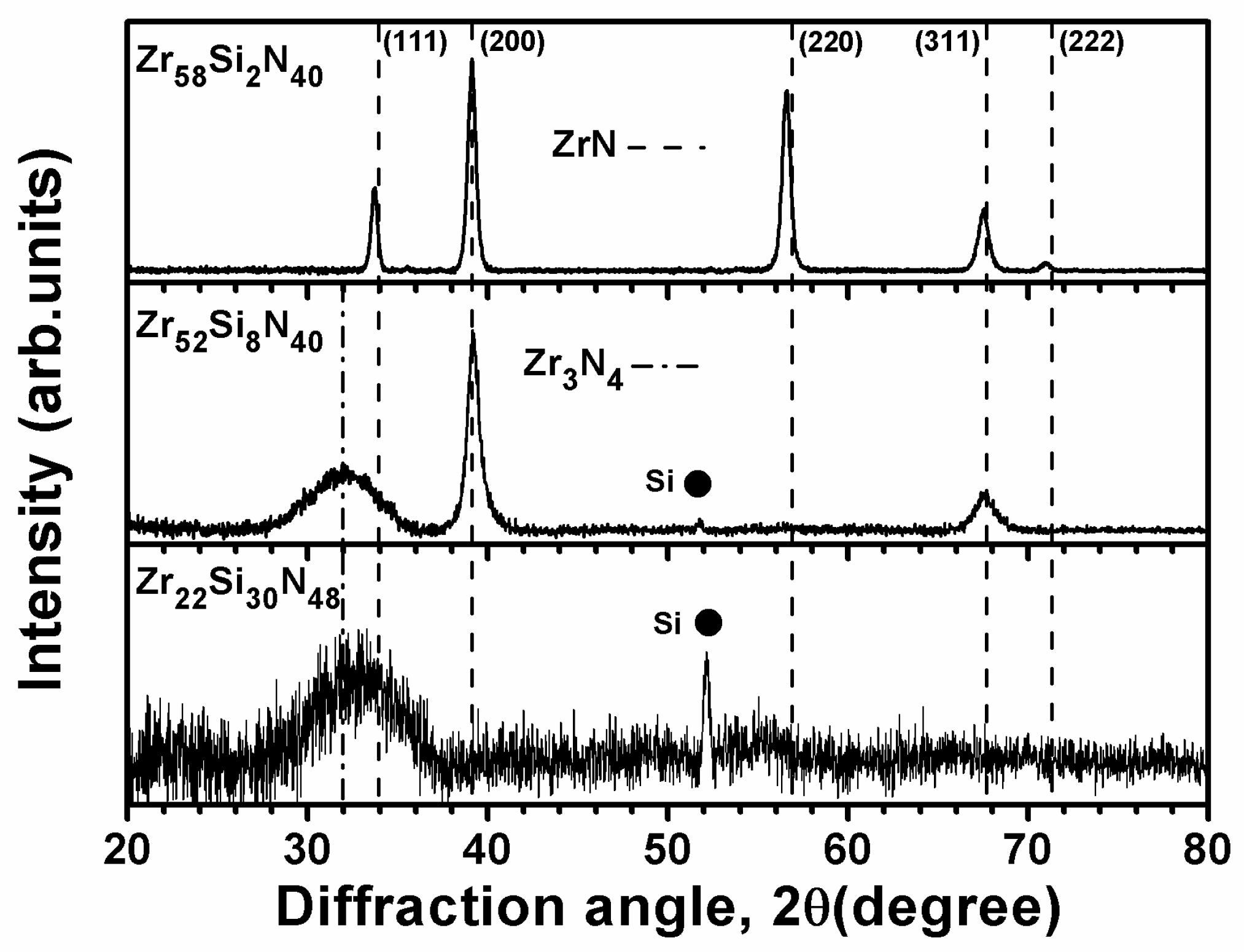
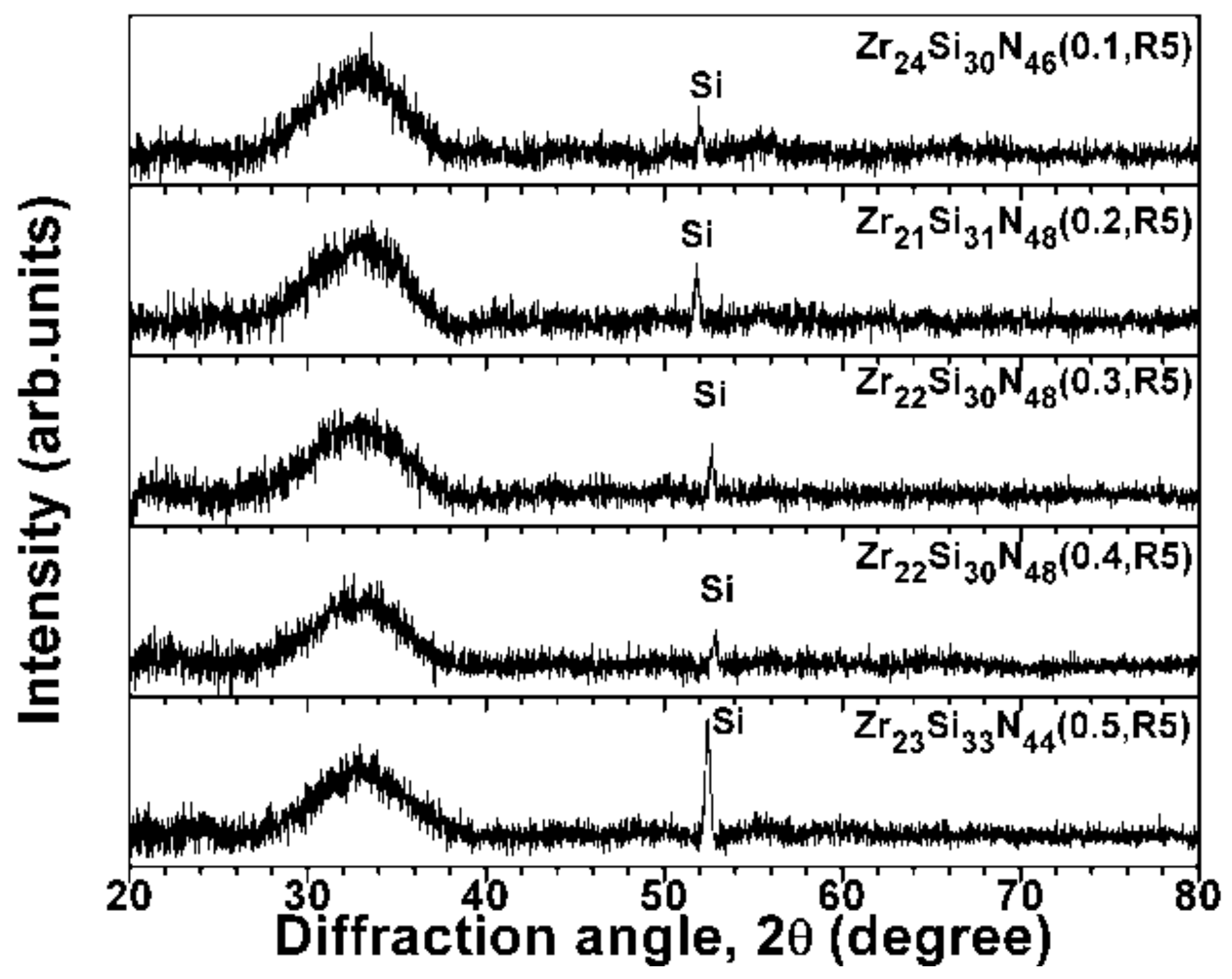
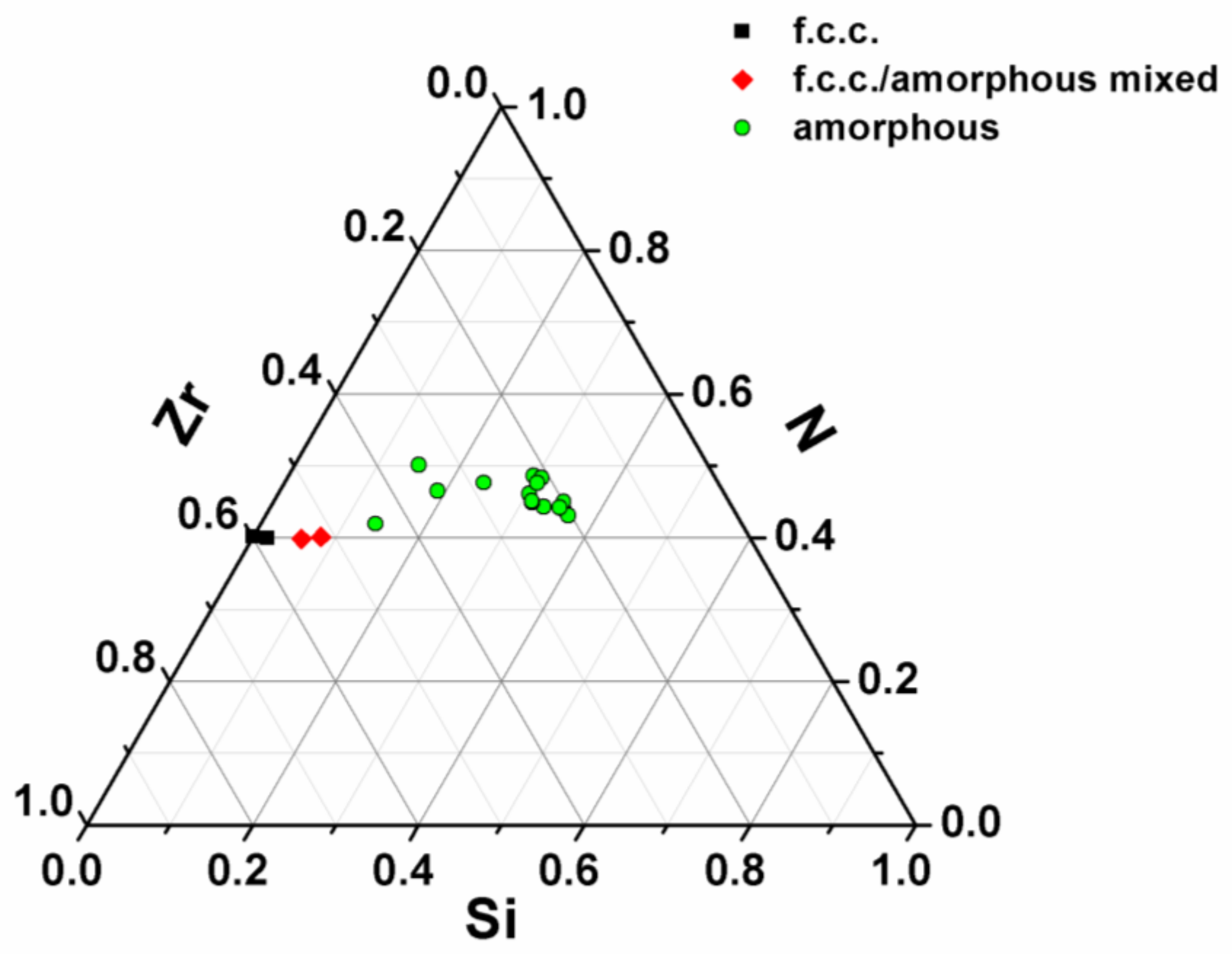
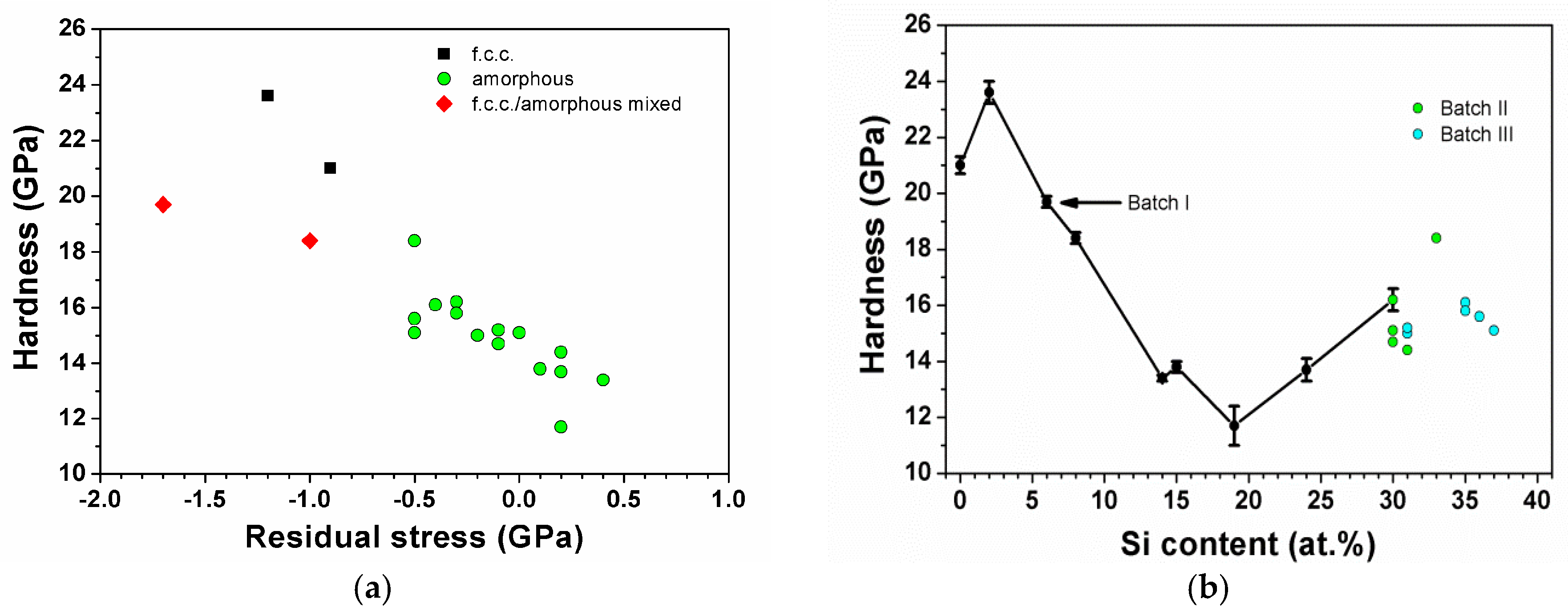
3.1. As-Deposited Zr–Si–N Coatings
Table 1 lists the sputtering variables, chemical compositions, and thicknesses of the Zr–Si–N coatings prepared in this study. The sputtering times were controlled to deposit coatings with thicknesses ranging from 890 to 1080 nm; therefore the indentation depth of 80 nm fitted the 1/10 rule for determining the mechanical properties of the coatings. The oxygen contents in the Zr–Si–N coatings were 0.8–1.1 at.%. The samples could be designated in the form ZrxSiyN(100–x−y)(f,Rx), where f is the (N2/(N2 + Ar)) flow ratio and Rx is the substrate holder rotation speed (x rpm) in the sputtering process. Figure 1 illustrates the XRD patterns of the as-deposited Batch-II Zr–Si–N coatings prepared using sputter powers of WZr = 100 W and WSi = 100 W, a substrate holder rotation speed of 5 rpm, and various (N2/(N2 + Ar)) flow ratios ranging from 0.1 to 0.5. All the Batch II Zr–Si–N coatings with a high Si content of 30–33 at.% exhibited an X-ray amorphous phase and similar chemical compositions. The deposition rate decreased from 10.8, to 8.8, to 7.2, to 6.1, and to 5.1 nm/min as the (N2/(N2 + Ar)) flow ratio was increased from 0.1, to 0.2, to 0.3, to 0.4, and to 0.5, respectively. Moreover, the Batch III Zr–Si–N coatings prepared using sputter powers of WZr = 100 W and WSi = 100 W, a substrate holder rotation speed of 1–30 rpm, and a (N2/(N2 + Ar)) flow ratio of 0.4 also exhibited similar chemical compositions (31–37 at.% Si), a deposition rate of 5.9–6.9 nm/min, and an X-ray amorphous phase (not discussed in this paper). Figure 2 illustrates the ternary diagram of the phase distribution of all the Zr–Si–N coatings, including the Batch I coatings prepared using various sputtering powers, a substrate holder rotation speed of 5 rpm, and a (N2/(N2 + Ar)) flow ratio of 0.4, as described in our previous study []. These coatings were classified into three phase types: face-centered cubic (f.c.c.), amorphous, and f.c.c. and amorphous mixed phases.
       
    
    Table 1.
    Sputtering parameters, chemical compositions, thicknesses, mechanical properties, and residual stresses of Zr–Si–N coatings.


    Figure 1.
      XRD patterns of as-deposited Zr–Si–N coatings prepared on Si substrates using various (N2/(N2 + Ar)) flow ratios, a substrate holder rotation speed of 5 rpm, and sputter powers of WZr = 100 W and WSi = 100 W.


    Figure 2.
      Phase distribution of Zr–Si–N coatings.
  
Figure 3a shows the relationship between the nanoindentation hardness and residual stress of the Zr–Si–N coatings. In each of the three coating types, the nanoindentation hardness levels exhibited decreasing tendencies as the residual stress varied from compressive toward tensile. Figure 3b shows the relationship between the nanoindentation hardness and Si content of the Zr–Si–N coatings; these X-ray amorphous-phase coatings with a high Si content of 30–37 at.% exhibited a high hardness level, which was similar to that of X-ray amorphous-phase coatings with an Si content of 14–24 at.%. The bonding characteristics of the X-ray amorphous-phase coatings exhibiting divergent mechanical properties were further analyzed. Because the hardness levels of the moldable optical glasses ranged from 3.2 to 7.0 GPa, the protective coatings on the glass molding dies exhibiting a hardness level higher than 10 GPa were preferred []. Therefore, Zr–Si–N coatings with a high Si content of 30 at.% exhibiting nanoindentation hardness higher than 14.4 GPa should be suitable for protective coatings.
      
    
    Figure 3.
      Relationships between nanoindentation hardness and (a) residual stress and (b) Si content of Zr–Si–N coatings.
  
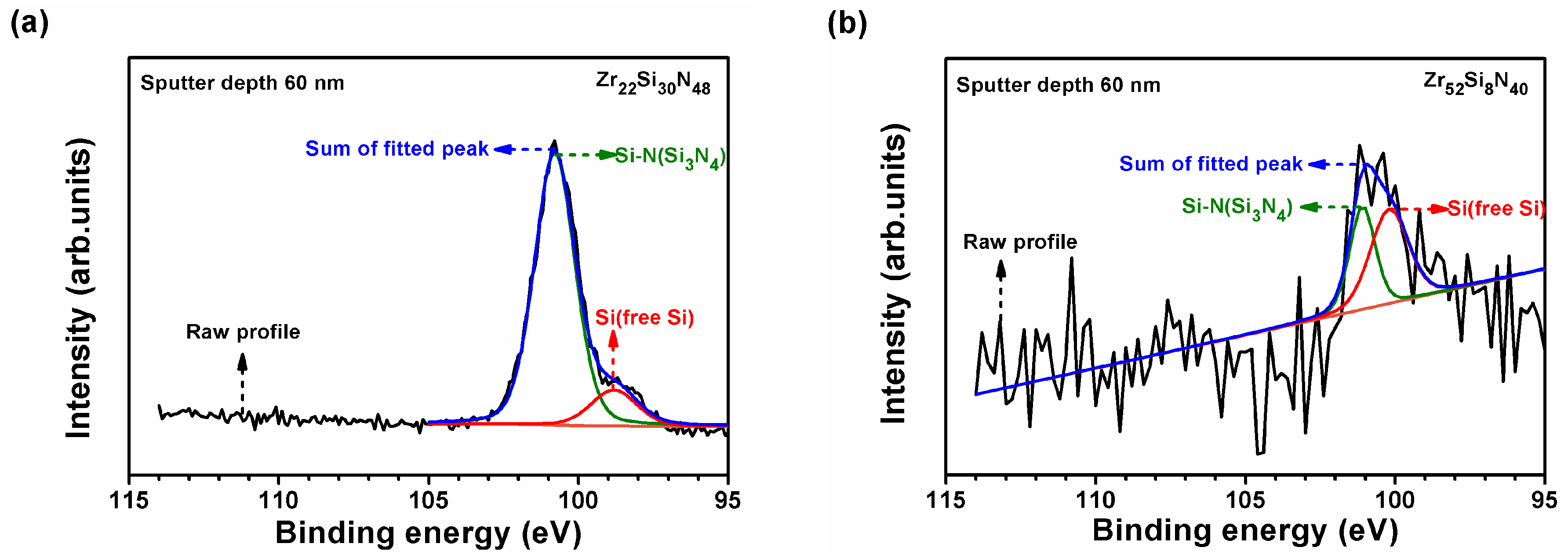
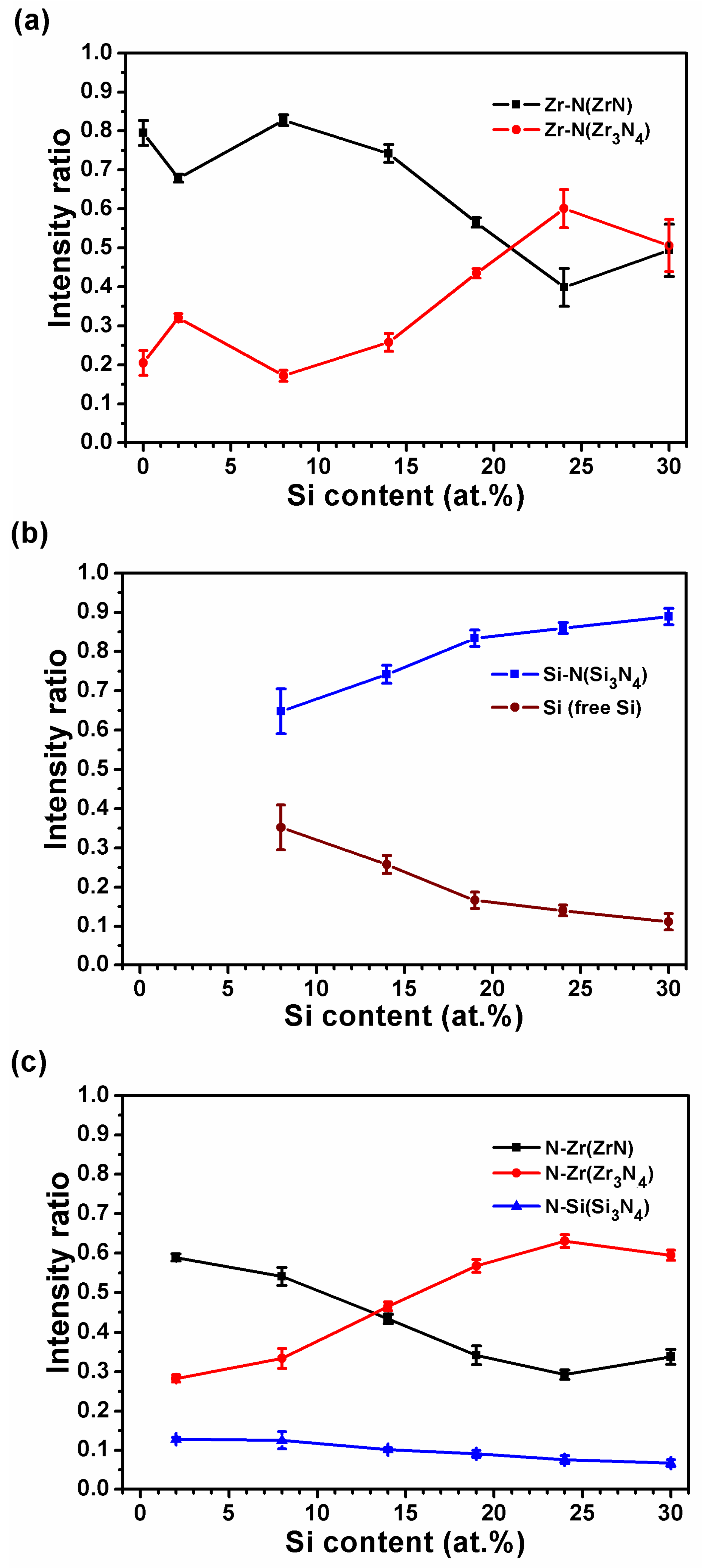
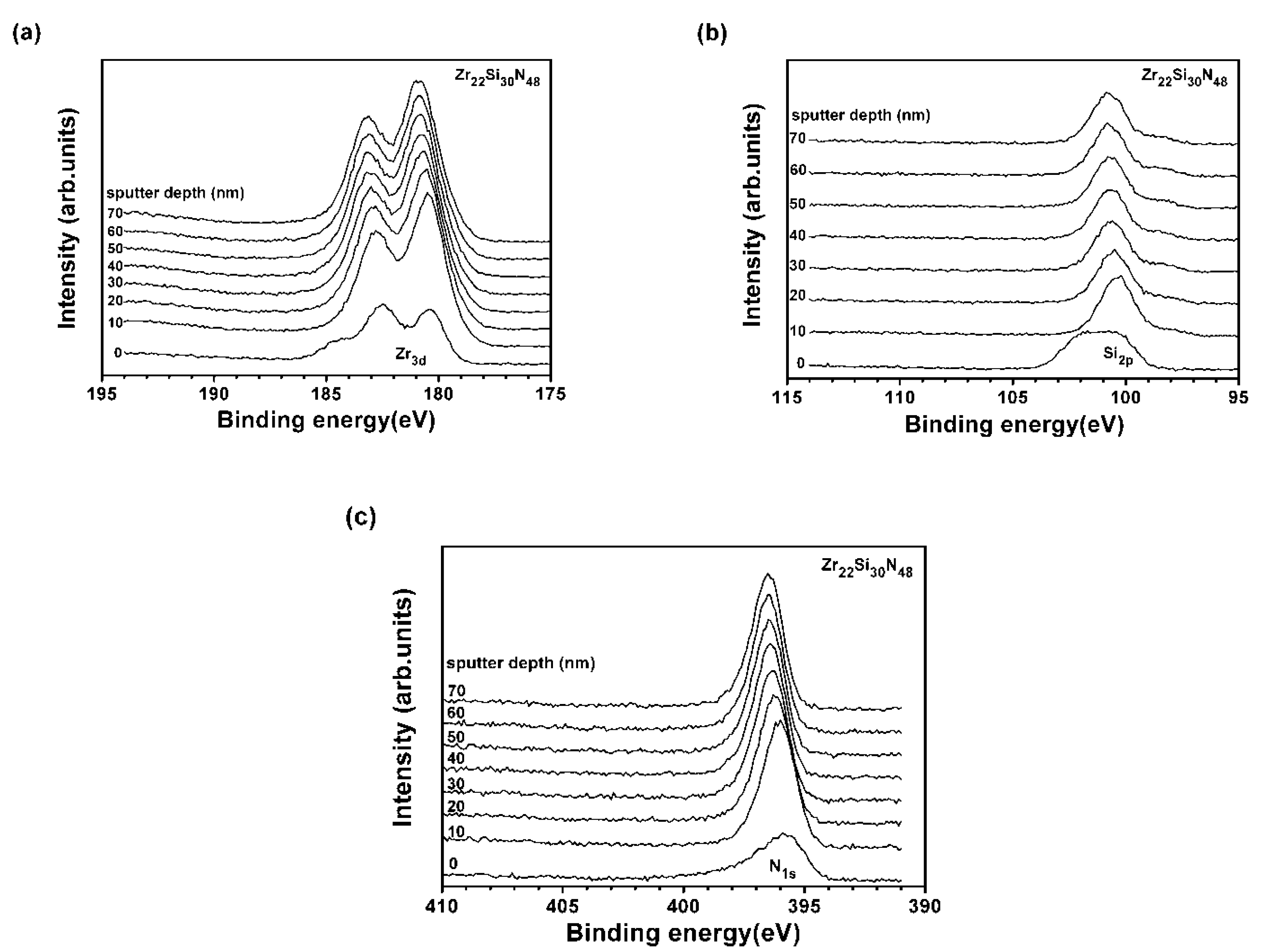
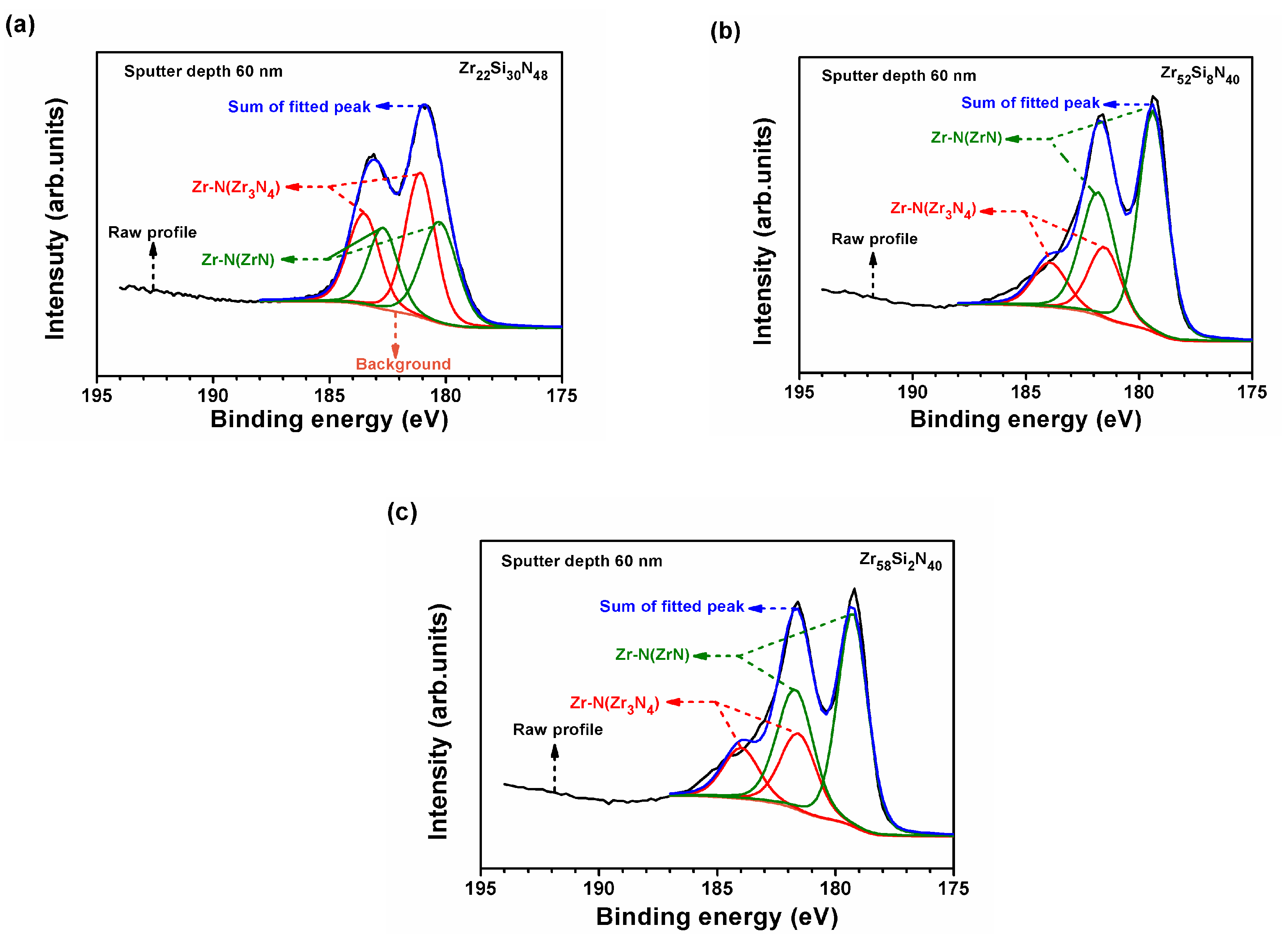
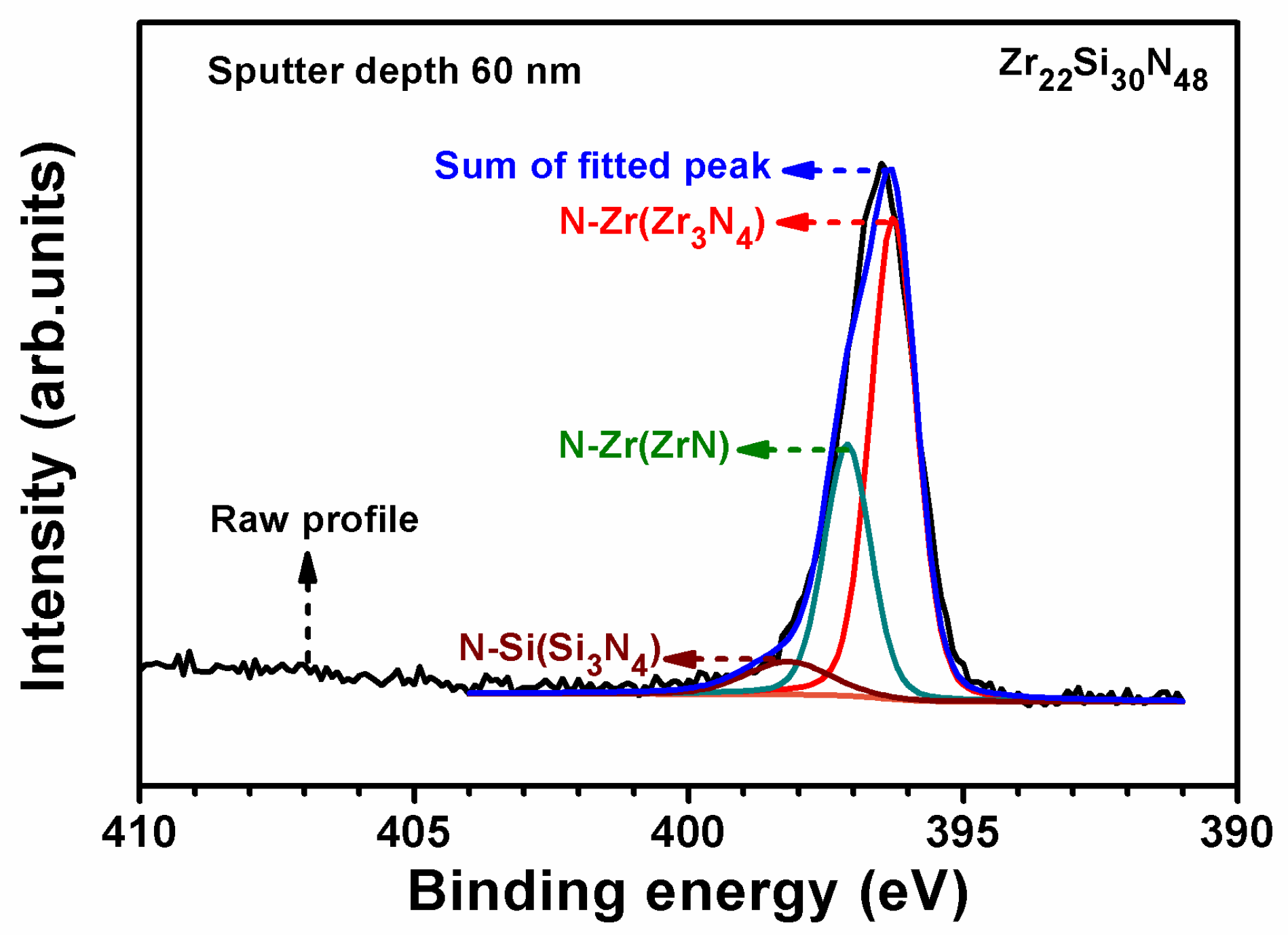
3.2. XPS Study of Zr–Si–N Coatings
In a previous study [], the low-Si-content (0–2 at.%) Zr–Si–N coatings exhibited an f.c.c. structure, whereas the medium-Si-content (6–8 at.%) coatings exhibited a mixture of f.c.c. and amorphous phases, and the high-Si-content (14–37 at.%) coatings exhibited X-ray amorphous structures. Figure 4 shows the XRD reflections of Zr58Si2N40(0.4,R5), Zr52Si8N40(0.4,R5), and Zr22Si30N48(0.4,R5) coatings, respectively representing the aforementioned three classifications. Figure 5 shows the XPS depth profiles of Zr 3d, Si 2p, and N 1s core levels of the as-deposited Zr22Si30N48(0.4,R5) coatings. The profiles of each element at a depth range of 10–70 nm were similar, whereas the profiles on the free surface exhibited deviations caused by the contamination from O. The oxygen content of the as-deposited Zr22Si30N48(0.4,R5) coatings was 0.8 at.%, examined from the surface of the samples by using an FE-EPMA. Figure 6a shows a curve fitting of the Zr profile at a depth of 60 nm of the Zr22Si30N48(0.4,R5) coatings; the Zr profile was split into two sets of doublets, representing Zr–N bonds for two compounds, ZrN and Zr3N4. The Zr 3d5/2 signals were determined at 180.22 ± 0.03 and 181.01 ± 0.06 eV for ZrN and Zr3N4, respectively, which exhibited a count ratio of 46:54. Figure 6b,c show the curve fitting of the Zr profiles at a depth of 60 nm of the Zr52Si8N40(0.4,R5) and Zr58Si2N40(0.4,R5) coatings, respectively; ZrN was the dominant Zr compound. The Zr 3d5/2 signals were 179.14 and 181.09 eV for ZrN and Zr3N4 in the Zr52Si8N40(0.4,R5) coatings, respectively, whereas these signals were 179.30 and 181.61 eV for ZrN and Zr3N4 in the Zr58Si2N40(0.4,R5) coatings, respectively.
      
    
    Figure 4.
      XRD patterns of Zr58Si2N40(0.4,R5), Zr52Si8N40(0.4,R5), and Zr22Si30N48(0.4,R5) coatings.


    Figure 5.
      XPS depth profiles of (a) Zr 3d; (b) Si 2p; and (c) N 1s of Zr22Si30N48(0.4,R5) coatings.


    Figure 6.
      XPS profiles of Zr 3d core levels of (a) Zr22Si30N48(0.4,R5); (b) Zr52Si8N40(0.4,R5); and (c) Zr58Si2N40(0.4,R5) coatings at a depth of 60 nm.
  
Table 2 lists all the binding energies for the bonds from ZrN, Zr3N4, and Si3N4 compounds in the Zr–Si–N coatings. The binding energies of Zr 3d5/2 related to Zr–N bonds for ZrN and Zr3N4 compounds were in the range of 179.14–180.22 and 180.75–181.61 eV, respectively, which were comparable to the reported values of 179.6 eV for ZrNx and 181.0 eV for ZrN1+x []. Figure 7a shows that the Si 2p of Zr22Si30N48(0.4,R5) coatings comprised two signals, 98.51 ± 0.11 and 100.59 ± 0.13 eV for free Si and Si–N bonds, respectively. The Si substrate without the aforementioned coatings exhibited a Si 2p signal of 99.35 ± 0.01 eV. Choi et al. [] reported that free Si at a binding energy of 99.3 eV was observed for Ti–Si–N coatings with an Si content >17 at.% because of the deficiency of N. Figure 7b shows that the Si 2p of Zr52Si8N40(0.4,R5) coatings comprised 98.92 and 100.68 eV signals for free Si and Si–N bonds, respectively. Because the Si content was 2 at.% only for the Zr58Si2N40(0.4,R5) coatings, the Si signal was undetectable because of the analysis limitation. The binding energies of Si 2p related to free Si and Si–N bonds for Si3N4 compound were in the range of 98.41–98.92 and 100.59–100.89 eV, respectively. The latter value exhibited a lower correlation to the reported value of 102.0 eV for Zr3N4 film []. Figure 8 shows that N 1s of Zr22Si30N48(0.4,R5) coatings comprised signals of 396.97 ± 0.11, 396.13 ± 0.12, and 397.94 ± 0.18 eV for N–Zr bond in ZrN, N–Zr bond in Zr3N4, and N–Si bond in Si3N4, respectively. The binding energies of N 1s of all the Zr–Si–N coatings related to N–Zr in ZrN, N–Zr in Zr3N4, and N–Si in Si3N4 were in the range of 396.87–397.05, 396.03–396.20, and 397.94–398.58 eV, respectively, which were higher than the reported values of 396.3, 395.4, and 397.7 eV [].
       
    
    Table 2.
    Binding energies of Zr–Si–N(0.4,R5) coatings.


    Figure 7.
      XPS profiles of Si 2p core levels of (a) Zr22Si30N48(0.4,R5) and (b) Zr52Si8N40(0.4,R5) coatings at a depth of 60 nm.


    Figure 8.
      XPS profiles of N 1s core levels of Zr22Si30N48(0.4,R5) coatings at a depth of 60 nm.
  
Figure 9 shows the variations in bond characteristics for various Si levels of Zr–Si–N(0.4,R5) coatings. Figure 9a,c show that Zr and N were likely to form a Zr3N4 compound as the Si content in the coatings increased, whereas Si formed Si–N bonds with increasing Si content in the coatings (Figure 9b). Thus, the bond characteristics of Zr28Si24N48(0.4,R5) and Zr22Si30N48(0.4,R5) coatings are Zr3N4- and Si3N4-dominated; therefore, the Zr–Si–N coatings with higher Si content of 24–30 at.% exhibited the hardness of Si3N4 at 18–19 GPa [,,].
      
    
    Figure 9.
      XPS signal ratios of (a) Zr; (b) Si; and (c) N of Zr–Si–N(0.4,R5) coatings.
  
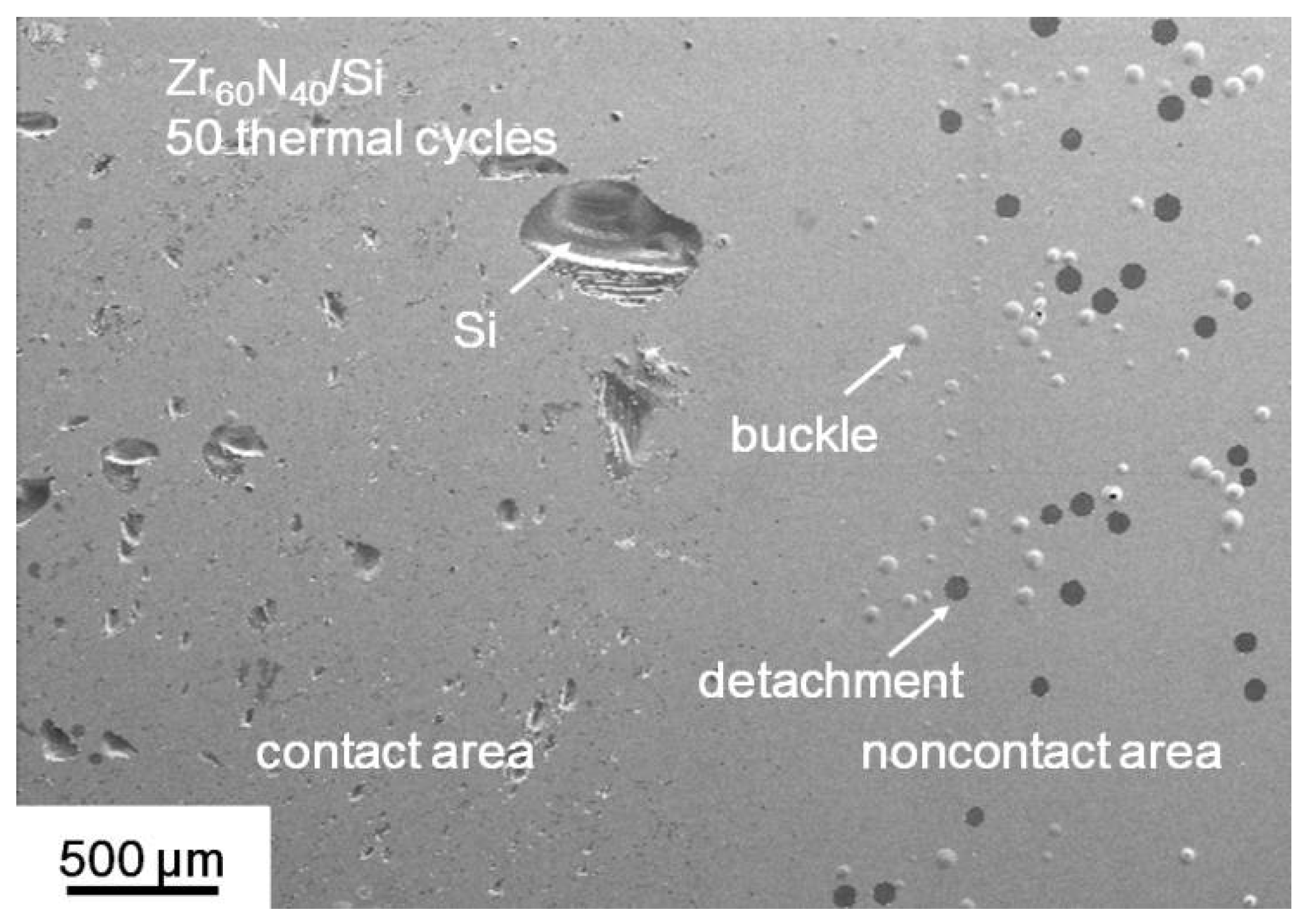
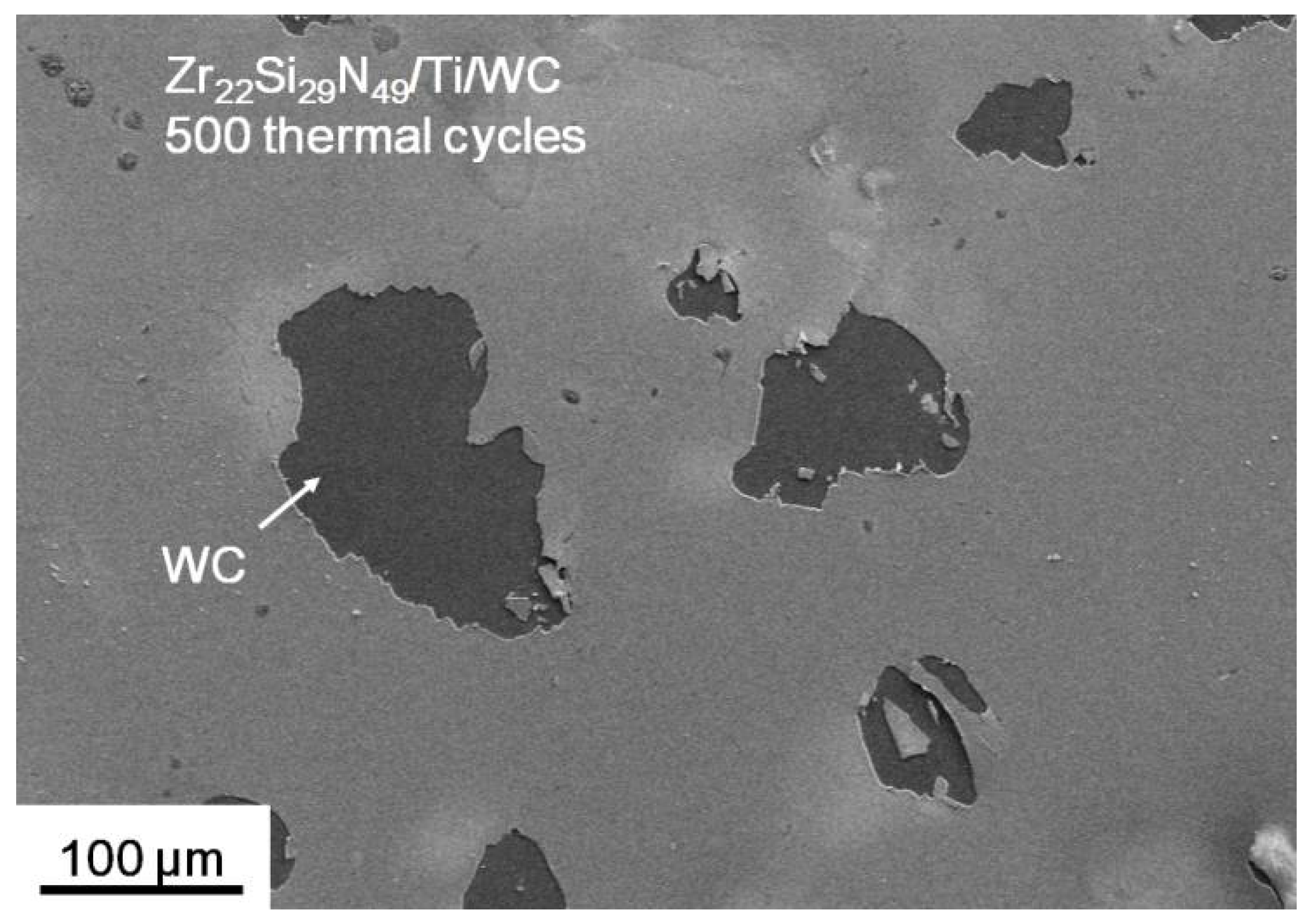
3.3. Thermal Stability and Chemical Inertness of Zr–Si–N Coatings
In our previous study [], high-Si-content (15–30 at.%) Zr–Si–N(0.4,R5) coatings exhibited oxidation resistance levels superior to those of low- and medium-Si-content coatings through examination of their oxide layer thicknesses after they were annealed at 600 °C in 1% O2–99% Ar for up to 100 h. The improvement of oxidation resistance was attributed to the formation of amorphous Si–Zr–O oxide scales, which were restricted following oxygen diffusion; thus, the mechanical properties of the high-Si-content (15–30 at.%) Zr–Si–N coatings were similar to those of as-deposited coatings. In the glass molding process, the molded products transfer the surface quality (figure and roughness) from the molding dies. Therefore, a coating roughness maintained at a nanoscale over a long lifetime is preferred. Table 3 shows the surface roughness variations of Zr–Si–N(0.4,R5) coatings during thermal cycle annealing (270–600 °C) in a realistic molding atmosphere (15-ppm O2–N2). The inner positions of the coatings indicated the area contacted SiO2–B2O3–BaO-based glass plates during thermal cycle annealing. The chemical inertness of the coatings against glass was evaluated by the presence of surface damage, such as scraps or dips [], and flaked or island oxides [], which consecutively result in roughness variation. The surface roughness variations on the outer positions indicated the thermal stability of the coatings during the glass molding process. The as-deposited Zr–Si–N(0.4,R5) coatings prepared on Si substrates exhibited a surface roughness of 0.3–1.0 nm. The surfaces of the outer positions (noncontact area in Figure 10) of low-Si-content Zr60N40(0.4,R5) and Zr58Si2N40(0.4,R5) coatings exhibited severely circular buckle formation following detachment after 50 thermal cycles, whereas black dips exposing the Si substrate were observed in the inner positions (contact area in Figure 10), which implied sticking and detachment. The Zr52Si8N40(0.4,R5) and Zr44Si14N42(0.4,R5) coatings exhibited similar dips in the contact area after 50 thermal cycles, whereas a low surface roughness level of 0.4–0.7 nm was maintained in the noncontact area after 250 cycles. The Zr35Si15N50(0.4,R5) and Zr34Si19N47(0.4,R5) coatings exhibited dips in the contact area after 250 thermal cycles, whereas a low surface roughness level of 0.6–0.7 nm was maintained in their noncontact area after 250 cycles. Undetached parts of the contact area of the Zr35Si15N50(0.4,R5) and Zr34Si19N47(0.4,R5) coatings exhibited roughness values of 4.0 and 2.1 nm, respectively. The Zr28Si24N48(0.4,R5) coatings maintained a smooth surface in the contact and noncontact areas after 250 cycles; however, dips occurred after 500 thermal cycles even though the surface roughness levels of the undetached part of the contact area and the noncontact area were 0.7 and 0.5 nm, respectively. For the amorphous Zr–Si–N(0.4,R5) coatings (14–24 at.% Si), a low surface roughness level of 0.5–0.7 nm was maintained in the noncontact area after 750 cycles. Therefore, the X-ray amorphous-phase Zr–Si–N coatings exhibited high thermal stability in the glass molding process, but their chemical inertness was relatively insufficient.
       
    
    Table 3.
    Surface roughness variations of Zr–Si–N(0.4,R5) coatings after thermal cycle annealing.


    Figure 10.
      Surface morphology of the Zr60N40(0.4,R5)/Si assembly after 50 thermal cycles.
  
Cemented carbide is a representative die material for glass molding. A Ti interlayer of 100 nm was inserted to fabricate the Zr–Si–N/Ti/WC assembly, which prevented buckle formation during repeated thermal cycle annealing []. The Zr22Si30N48(0.4,R5) process was conducted again to fabricate a Zr22Si29N49/Ti/WC assembly; this assembly exhibited a surface roughness of 1.5 nm in the as-deposited state, which was higher than those of the Zr–Si–N(0.4,R5) coatings prepared on Si wafers. The Zr22Si29N49/Ti/WC assembly maintained a smooth surface in the contact and noncontact areas after 250 and 400 thermal cycles; however, black dips of the Zr22Si29N49/Ti coatings occurred after 500 thermal cycles (Figure 11). No buckle formation was observed. The 450-cycle-treated sample showed no sticking marks. The as-prepared Zr22Si29N49/Ti/WC assembly exhibited a surface roughness of 1.5 nm, which was lower than that of the Ta26Si16N58/Ti/WC assembly (2.9 nm), indicating a higher chemical inertness of 1400 thermal cycles against SiO2–B2O3–BaO-based glass [].
      
    
    Figure 11.
      Surface morphology of the contact area of the Zr22Si29N49/Ti/WC assembly after 500 thermal cycles.
  
4. Conclusions
The Zr–Si–N coatings with an Si content higher than 14 at.% exhibited an X-ray amorphous phase. Moreover, the nanoindentation hardness level of the Zr–Si–N coatings with an Si content of >30 at.% was >14.4 GPa, which was higher than those of the coatings with an Si content of 14–24 at.%; this was attributed to the variation of bonding characteristics. The structure varied from crystalline ZrN-dominant to amorphous Zr3N4-dominant with increasing Si content in the Zr–Si–N coatings. The bond characteristics of Zr28Si24N48 and Zr22Si30N48 coatings exhibited a Zr3N4- and Si3N4-dominated nitride structure, and the nanoindentation hardness values were approximately similar to that of Si3N4. Buckle formation and the sticking effect became major disadvantages for protective coatings during the glass molding process. The Zr22Si29N49/Ti/WC assembly was suitable as a protective coating against SiO2–B2O3–BaO-based glass for annealing for 450 thermal cycles at 270 °C and 600 °C in a 15-ppm O2–N2 atmosphere. Reducing the surface roughness by introducing an interlayer in the protective coating assembly and increasing the chemical inertness of the protective coatings are major concerns to be addressed in the future.
Author Contributions
L.-C.C. and Y.-I.C. conceived and designed the experiments; Y.-Z.Z. and S.-C.C. performed the coating experiments; Y.-Z.Z. and B.-W.L. performed the annealing experiments; Y.-Z.Z. and B.-W.L. analyzed the XPS data; Y.-I.C. wrote the paper. 
Funding
This research was funded by the Ministry of Science and Technology, Taiwan (105-2221-E-019-007-MY3 and 106-2221-E-131-002). 
Conflicts of Interest
The authors declare no conflict of interest. The founding sponsors had no role in the design of the study; in the collection, analyses, or interpretation of data; in the writing of the manuscript, and in the decision to publish the results.
References
- Katsuki, M. Transferability of glass lens molding. Proc. SPIE 2006, 6149, 61490M. [Google Scholar]
 - Maschmeyer, R.O.; Andrysick, C.A.; Geyer, T.W.; Meissner, H.E.; Parker, C.J.; Sanford, L.M. Precision molded-glass optics. Appl. Opt. 1983, 22, 2410–2412. [Google Scholar] [CrossRef] [PubMed]
 - Yi, A.Y.; Jain, A. Compression molding of aspherical glass lenses—A combined experimental and numerical analysis. J. Am. Ceram. Soc. 2005, 88, 579–586. [Google Scholar] [CrossRef]
 - Monji, H.; Aoki, M.; Torii, H.; Okinaka, H. Molding Method for Producing Optical Glass Element. U.S. Patent 4,629,487A, 16 December 1986. [Google Scholar]
 - Kuribayashi, K.; Sakai, M.; Monji, H.; Aoki, M.; Okinaka, H.; Torii, H. Mold for Press-Molding Glass Optical Elements and a Molding Method Using the Same. U.S. Patent 4,685,948A, 11 August 1987. [Google Scholar]
 - Wu, F.B.; Chen, W.Y.; Duh, J.G.; Tsai, Y.Y.; Chen, Y.I. Ir-based multi-component coating on tungsten carbide by RF magnetron sputtering process. Surf. Coat. Technol. 2003, 163–164, 227–232. [Google Scholar] [CrossRef]
 - Klocke, F.; Bouzakis, K.D.; Georgiadis, K.; Gerardis, S.; Skordaris, G.; Pappa, M. Adhesive interlayers’ effect on the entire structure strength of glass molding tools’ Pt–Ir coatings by nano-tests determined. Surf. Coat. Technol. 2011, 206, 1867–1872. [Google Scholar] [CrossRef]
 - Chao, C.L.; Huo, C.B.; Chou, W.C.; Lin, Y.R.; Ma, K.J.; Chien, H.H. Study on the design of precious metal based protective films for glass moulding process. Surf. Coat. Technol. 2013, 231, 567–572. [Google Scholar] [CrossRef]
 - Liu, S.C.; Chen, Y.I.; Tsai, H.Y.; Lin, K.C.; Chen, Y.H. Thermal stability of Ir–Re coatings annealed in oxygen containing atmospheres. Surf. Coat. Technol. 2013, 237, 105–111. [Google Scholar] [CrossRef]
 - Liu, S.C.; Chen, Y.I.; Shyu, J.J.; Tsai, H.Y.; Lin, K.Y.; Chen, Y.H.; Lin, K.C. The chemical inertness of Ir–Re and Ta–Ru coatings in molding B2O3-ZnO-La2O3-based glass. Surf. Coat. Technol. 2014, 259, 352–357. [Google Scholar] [CrossRef]
 - Zhu, X.Y.; Wei, J.J.; Chen, L.X.; Liu, J.L.; Hei, L.F.; Li, C.M.; Zhang, Y. Anti-sticking Re–Ir coating for glass molding process. Thin Solid Films 2015, 584, 305–309. [Google Scholar] [CrossRef]
 - Uno, K.; Fujino, T.; Nakamori, H. Process for producing mold used for obtaining press molded glass article. U.S. Patent 5,008,002A, 16 April 1991. [Google Scholar]
 - Hirota, S.; Oogami, Y.; Hashimoto, K. Method of molding a glass composition into an optical element. U.S. Patent 6,776,007B2, 17 August 2004. [Google Scholar]
 - Kleer, G.; Doell, W. Ceramic multilayer coatings for glass moulding applications. Surf. Coat. Technol. 1997, 94–95, 647–651. [Google Scholar] [CrossRef]
 - Hock, M.; Schäffer, E.; Döll, W.; Kleer, G. Composite coating materials for the moulding of diffractive and refractive optical components of inorganic glasses. Surf. Coat. Technol. 2003, 163–164, 689–694. [Google Scholar] [CrossRef]
 - Lin, C.H.; Duh, J.G.; Yau, B.S. Processing of chromium tungsten nitride hard coatings for glass molding. Surf. Coat. Technol. 2006, 201, 1316–1322. [Google Scholar] [CrossRef]
 - Fischbach, K.D.; Georgiadis, K.; Wang, F.; Dambon, O.; Klocke, F.; Chen, Y.; Yi, A.Y. Investigation of the effects of process parameters on the glass-to-mold sticking force during precision glass molding. Surf. Coat. Technol. 2010, 205, 312–319. [Google Scholar] [CrossRef]
 - Lin, T.N.; Han, S.; Weng, K.W.; Lee, C.T. Investigation on the structural and mechanical properties of anti-sticking sputtered tungsten chromium nitride films. Thin Solid Films 2013, 529, 333–337. [Google Scholar] [CrossRef]
 - Chang, Y.Y.; Cheng, C.M.; Liou, Y.Y.; Tillmann, W.; Hoffmann, F.; Sprute, T. High temperature wettability of multicomponent CrAlSiN and TiAlSiN coatings by molten glass. Surf. Coat. Technol. 2013, 231, 24–28. [Google Scholar] [CrossRef]
 - Chen, Y.I.; Wang, H.H. Oxidation resistance and mechanical properties of Cr–Ta–Si–N coatings in glass molding processes. Surf. Coat. Technol. 2014, 260, 118–125. [Google Scholar] [CrossRef]
 - Chen, Y.I.; Cheng, Y.R.; Chang, L.C.; Lu, T.S. Chemical inertness of Ta–Si–N coatings in glass molding. Thin Solid Films 2015, 584, 66–71. [Google Scholar] [CrossRef]
 - Chen, Y.I.; Cheng, Y.R.; Chang, L.C.; Lee, J.W. Chemical inertness of Cr–W–N coatings in glass molding. Thin Solid Films 2015, 593, 102–109. [Google Scholar] [CrossRef]
 - Chang, L.C.; Zheng, Y.Z.; Gao, Y.X.; Chen, Y.I. Mechanical properties and oxidation resistance of sputtered Cr–W–N coatings. Surf. Coat. Technol. 2017, 320, 196–200. [Google Scholar] [CrossRef]
 - Vepřek, S.; Haussmann, M.; Reiprich, S.; Shizhi, L.; Dian, J. Novel thermodynamically stable and oxidation resistant superhard coating materials. Surf. Coat. Technol. 1996, 86–87, 394–401. [Google Scholar] [CrossRef]
 - Choi, J.B.; Cho, K.; Lee, M.H.; Kim, K.H. Effects of Si content and free Si on oxidation behavior of Ti–Si–N coating layers. Thin Solid Films 2014, 447–448, 365–370. [Google Scholar] [CrossRef]
 - Steyer, P.; Pilloud, D.; Pierson, J.F.; Millet, J.-P.; Charnay, M.; Stauder, B.; Jacquot, P. Oxidation resistance improvement of arc-evaporated TiN hard coatings by silicon addition. Surf. Coat. Technol. 2006, 201, 4158–4162. [Google Scholar] [CrossRef]
 - Nose, M.; Zhou, M.; Nagae, T.; Mae, T.; Yokota, M.; Saji, S. Properties of Zr–Si–N coatings prepared by RF reactive sputtering. Surf. Coat. Technol. 2000, 132, 163–168. [Google Scholar] [CrossRef]
 - Pilloud, D.; Pierson, J.F.; Marco de Lucas, M.C.; Alnot, M. Stabilisation of tetragonal zirconia in oxidized Zr–Si–N nanocomposite coatings. Appl. Surf. Sci. 2004, 229, 132–139. [Google Scholar] [CrossRef]
 - Zeman, P.; Musil, J. Difference in high-temperature oxidation resistance of amorphous Zr–Si–N and W–Si–N films with a high Si content. Appl. Surf. Sci. 2006, 252, 8319–8325. [Google Scholar] [CrossRef]
 - Musil, J. Hard nanocomposite coatings: Thermal stability, oxidation resistance and toughness. Surf. Coat. Technol. 2012, 207, 50–65. [Google Scholar] [CrossRef]
 - Chen, Y.I.; Chang, S.C.; Chang, L.C. Oxidation resistance and mechanical properties of Zr–Si–N coatings with cyclic gradient concentration. Surf. Coat. Technol. 2017, 320, 168–173. [Google Scholar] [CrossRef]
 - Chen, Y.I.; Lin, K.Y.; Wang, H.H.; Cheng, Y.R. Characterization of Ta–Si–N coatings prepared using direct current magnetron co-sputtering. Appl. Surf. Sci. 2014, 305, 805–816. [Google Scholar] [CrossRef]
 - Chen, Y.I.; Lin, K.Y.; Wang, H.H.; Lin, K.C. Thermal stability of TaN, CrTaN, TaSiN, and CrTaSiN hard coatings in oxygen-containing atmospheres. Surf. Coat. Technol. 2014, 259, 159–166. [Google Scholar] [CrossRef]
 - Moulder, J.F.; Stickle, W.F.; Sobol, P.E.; Bomben, K.D. Handbook of X-ray Photoelectron Spectroscopy; Chastain, J., King, R.C., Eds.; Physical Electronics: Chanhassen, MN, USA, 1995. [Google Scholar]
 - Oliver, W.C.; Pharr, G.M. An improved technique for determining hardness and elastic modulus using load and displacement sensing indentation experiments. J. Mater. Res. 1992, 7, 1564–1583. [Google Scholar] [CrossRef]
 - Bennett, J.M. Rough Surfaces, 2nd ed.; Imperial College Press: London, UK, 1999. [Google Scholar]
 - Janssen, G.C.A.M.; Abdalla, M.M.; van Keulen, F.; Pujada, B.R.; van Venrooy, B. Celebrating the 100th anniversary of the Stoney equation for film stress: Developments from polycrystalline steel strips to single crystal silicon wafers. Thin Solid Films 2009, 517, 1858–1867. [Google Scholar] [CrossRef]
 - Brantly, W.A. Calculated elastic constants for stress problems associated with semiconductor devices. J. Appl. Phys. 1973, 44, 534–535. [Google Scholar] [CrossRef]
 - Bertóti, I. Characterization of nitride coatings by XPS. Surf. Coat. Technol. 2002, 151–152, 194–203. [Google Scholar]
 - Chen, Y.H.; Guruz, M.; Chung, Y.W.; Keer, L.M. Thermal stability of hard TiN/SiNx multilayer coatings with an equiaxed microstructure. Surf. Coat. Technol. 2002, 154, 162–166. [Google Scholar] [CrossRef]
 - Dong, Y.; Zhao, W.; Yue, J.; Li, G. Crystallization of Si3N4 layers and its influences on the microstructure and mechanical properties of ZrN/Si3N4 nanomultilayers. Appl. Phys. Lett. 2006, 89, 121916. [Google Scholar] [CrossRef]
 - Abadias, G.; Uglov, V.V.; Saladukhin, I.A.; Zlotski, S.V.; Tolmachova, G.; Dub, S.N.; Janse van Vuuren, A. Growth, structural and mechanical properties of magnetron-sputtered ZrN/SiNx nanolaminated coatings, Surf. Coat. Technol. 2016, 308, 158–167. [Google Scholar] [CrossRef]
 
© 2018 by the authors. Licensee MDPI, Basel, Switzerland. This article is an open access article distributed under the terms and conditions of the Creative Commons Attribution (CC BY) license (http://creativecommons.org/licenses/by/4.0/).